

Siare Falco 202 Evo User Manual

Falco 202 Evo - 10.4”
Lung Ventilator
Turbine-driven ventilation
Touch Screen
User’s Manual


GENERAL INFORMATION
The information contained in this manual are the exclusive property of SIARE
Engineering International Group s.r.l. and may not be reproduced in any way
without authorisation. SIARE Engineering International Group s.r.l. reserves the
right to modify or replace this manual at any time without prior notice.
It is however recommended that you make sure you have the most recent
version of the manual. In the event of doubt, contact SIARE Engineering
International Group s.r.l. (see the address on page IX). The information
contained in the present User’s Manual can be considered correct, but do not
exclude professional knowledge by the user.
The operation and maintenance of Falco 202 Evo (10.4”) lung ventilator must be
entrusted to qualified technical personnel only. The responsibility of SIARE
Engineering International Group s.r.l. concerning the Falco 202 Evo (10.4”) lung
ventilator and its use is limited to what is indicated in the guarantee supplied.
The contents of this manual do not in any way limit the right of SIARE
Engineering International Group s.r.l. to revise, change or modify without prior
notice the equipment (including the relative software) described herein.
Unless otherwise specifically agreed in writing, SIARE Engineering International
Group s.r.l. is not obliged to supply such revisions, changes or modifications to
the owner or user of the equipment (including the relative software) described
herein.
The information contained in this manual refers to the versions of Falco 202 Evo
(10.4”) lung ventilator produced or updated after February 2019. It is possible
that some information may not apply to previous versions. Contact SIARE
Engineering International Group s.r.l. if you have any doubts.
User’s Manual, version DU3104101
Revision 1 - 01.02.2019
Falco 202 Evo
III
Observations
SIARE Engineering International Group s.r.l. wishes to thank you for purchasing
one of its products.
Any comment on the accuracy and usefulness of this User’s Manual would be
very helpful in allowing us to guarantee current and future users of the highquality level of our manuals. We would be grateful if you would send us your
comments (see address at page IX).
The SIARE trademark is used throughout this manual as an abbreviation for the
manufacturer: SIARE Engineering International Group s.r.l.
Directive 93/42 EEC
Definitions
Three symbols are used in this User’s Manual to indicate particularly important
information.
WARNING !!
This indicates a condition of danger for the patient or for the
User.
CAUTION
This indicates the possibility of danger to the lung ventilator.
NOTE
This indicates information worthy of note, making the operation
of the Falco 202 Evo lung ventilator more efficient or practical.
IV User manual, DU3104101

Warnings, cautions and notes
You are advised to carefully read the information given alongside the three
symbols shown on the previous page, since it contains considerations on
the safety, the special requirements for the use Falco 202 Evo (10.4”) lung
ventilator (hereinafter called lung ventilator) and the relative safety regulations.
In order to understand how the lung ventilator works and how to use it
correctly to ensure patient and user safety, the recommendations and
instructions contained in this manual must be read with care and understood.
In order to grant maximum reliability and to ensure the patient and User’s
safety, the lung ventilator was designed and manufactured following warranty
standards of quality of the product and its components. Any part of circuit
must therefore only be replaced with original spare parts supplied or checked
by SIARE.
The lung ventilator must only be used for the purposes specified herein and
the safety of the lung ventilator is therefore only guaranteed if it is used in
accordance with the instructions given in this manual.
The lung ventilator must only be used by qualified personnel and only in
equipped and dedicated rooms, according to the regulations in force in the
country where the lung ventilator is installed. Furthermore, during all the
operation of lung ventilator, it is required the presence of qualified personnel.
Regarding the general safety and to ensure correct technical assistance and
avoid possible physical damage to the patient, the maintenance schedule
foreseen in this manual must be respected; qualified personnel must only
carry out maintenance of the lung ventilator or authorised modifications to the
lung ventilator. The user of this product is solely responsible for any
operating defect caused by improper use or interventions carried out by third
parties other than specialised SIARE personnel.
The maintenance and the replacement of any part have to be performed by
authorized service personnel and only original SIARE spare parts or
components checked by SIARE should be used.
Regarding the general safety of the electro-medical equipment, it is important
to follow all rules about the interaction between the machine and the patient,
the User and the nearby environment.
For any repairs to lung ventilator (due to malfunctioning, defects or failures),
the user must contact SIARE or the authorised local Technical Service
Centre; it is advisable to specify the data on the identification label (model,
serial number, ……) when requesting intervention.
SIARE recommends establishing a maintenance and service contract with
SIARE or the local authorised service dealer in order to guarantee the
scheduled maintenance required to operate the lung ventilator in a safe and
correct manner.
Falco 202 Evo
V

To prevent the risk of fire, keep the lung ventilator and/or the oxygen tubes
away from matches, lit cigarettes and inflammable material, such as
anaesthetic gases and/or sources of heat.
Do not connect the lung ventilator to the patient by flexible connectors, and
antistatic or conductive tubes to prevent patient burnings during the use of
high frequency surgical equipment, especially dangerous with antistatic
tubes. The use of flexible connectors, antistatic or conductive tube is never
permitted with lung ventilator.
Do not use worn and consumed tubes or tubes contaminated by flammable
substances like grease or oil to deliver oxygen; (fabrics, oil and other fuels
can easily ignite and they intensively burn in air with high concentration of
oxygen.
In the event of fire or an unpleasant smell (e.g. a smell of burning), the lung
ventilator should immediately be disconnected from the electrical power
supply and from the battery (if fitted).
When coming into contact with any component of the lung ventilator, the
hospital procedures for the handling of infected material should always be
respected.
SIARE is aware that cleaning, sterilisation and disinfection procedures vary
considerably from one health structure to another. SIARE cannot be held
responsible for the efficacy of the cleaning and sterilisation procedures, nor
for the other procedures carried out while the patient is being treated. As
regards cleaning, sterilisation and disinfection of the product components, it
is therefore recommended that the regulations currently in force in the
country where the lung ventilator is installed be taken into consideration.
The lung ventilator was not designed as a total monitoring device: some
conditions of danger for the patients treated with vital support equipment will
not trigger any alarm.
Before using the lung ventilator or any connected component, carefully check
that the lung ventilator is functioning correctly; when needed, the preliminary
tests must be performed as described in the present manual.
Do not use pointed instruments, such as pencils, screwdrivers or the like to
make selections or settings as they could damage the surface of the LCD
panel.
Check the lung ventilator periodically as described in the relative
“Maintenance” chapter and do not use it if it is faulty or malfunctioning.
Replace any broken, missing, obviously worn, deformed or contaminated
parts immediately, with spare parts supplied by SIARE.
Do not connect external devices NOT manufactured or NOT authorized by
SIARE to the lung ventilator (example: scavenging systems, patient
simulators, etc…..), and not described in the present user’s manual: in case
of need contact SIARE.
VI User manual, DU3104101

The correct functioning of the lung ventilator can be impaired if original
SIARE spare parts and accessories are not used; the use of other
accessories is however allowed only if formally authorised by SIARE
in accordance with current safety regulations.
SIARE assumes all foreseen legal liability if the lung ventilator is used and
periodically maintained according to the instructions contained in this manual:
the Technical Assistance Report, drawn up and signed by the authorised
SIARE technician, is proof of the completion of the scheduled maintenance.
Notwithstanding the lung ventilator is equipped with a safety valve which
allows to the patient to breathe spontaneously the ambient air even in case of
gas supply failure, the auxiliary ventilation system must be always promptly
available; such a component is part of SIARE Engineering International
Group s.r.l. products range.
Falco 202 Evo
VII
WARNING !!
The lung ventilator is not approved for operation in places
where there is any risk of explosion.
Do not use the lung ventilator in the presence of flammable
gases.
The lung ventilator cannot be used in the presence of
explosive gases.
WARNING !!
The lung ventilator shall not be used in a hyperbaric
chamber.
The lung ventilator shall not be used with nitric oxide.
The lung ventilator shall not be used with helium or mixtures
with helium.
WARNING !!
Before starting the lung ventilator use, you have to carry out
the preliminary checks.
Before connecting the lung ventilator to other electrical
equipment not described in this manual, a request for
authorisation should be sent to Siare.
Qualified staff must make the regulation of ventilation
parameters.
WARNING !!
Do not block the gas intake port or emergency intake port,
thereby interfering with PATIENT ventilation.
WARNING !!
An auxiliary ventilation system is suggested for the patients for
which the lung ventilator represents a life support.
WARNING !!
Means for independent ventilation shall be available (i.e.
manual resuscitation bag with mask) whenever the lung
ventilator is in use.
VIII User manual, DU3104101

SIARE declines all civil and penal responsibility in the
following cases.
If the lung ventilator is used in conditions and for purposes
not stated or described in this manual.
If the lung ventilator is used by non-qualified personnel.
If periodic maintenance as foreseen by this manual has not
been carried out correctly or has been skipped.
If personnel not officially authorised by SIARE have
performed maintenance.
If non-original SIARE spare parts or components not checked
by SIARE have been used.
If the lung ventilator has been connected to equipment not
complying with the safety norms for the intended use.
Direct or indirect damage to persons or things caused by
unauthorised technical intervention or by improper use of the
lung ventilator not in accordance with the instructions
contained in the users and maintenance manual.
Year of manufacture
Check the identification data label of the Falco 202 Evo l(10.4”) lung ventilator in
the relative chapter.
Shelf life of medical device
The Directive 93/42EEC on medical devices foresees that the manufacturer
defines the shelf life of the device according to the intended purpose. The shelf
life foreseen by SIARE for the lung ventilator model Falco 202 Evo is 10 years.
Manufacturer
SIARE Engineering International Group s.r.l.
Via Giulio Pastore, 18 - 40056
Località Crespellano, 40053 Valsamoggia (BO), ITALY
Tel.: +39 051 969802 - Fax: +39 051 969366
Falco 202 Evo
E-mail: mail@siare.it - web: www.siare.it
IX
Electromagnetic Compatibility
The Falco 202 Evo (10.4”) lung ventilator is designed to operate in the specified
electromagnetic environment (see warning below).
The customer or the user of Falco 202 Evo lung ventilator should ensure that it is
used in such an electromagnetic environment.
The lung ventilator complies with the EN 60601-1-2 regulations
on Electromagnetic Compatibility of electro-medical equipment.
It is in any case highly recommended not to use the lung
ventilator adjacent to high-powered equipment or to units,
which emit strong electro-magnetic fields. Mobile phones,
cordless phones or other radio transmitters used in the vicinity
of the lung ventilator could influence its operation. Whenever
the lung ventilator should be necessarily used nearby to such
equipment, it will be required to supervise its normal operation.
In general, as regards the regulations regarding
“electromagnetic emissions”, “electromagnetic immunity”
and “recommended separation distances between portable
and mobile RF equipment and the device”, always refer to
what is described in the lung ventilator manual.
Requirements applicable to cables, transducers and other
accessories that could affect compliance with the requirements
of 6.1 and 6.2
X User manual, DU3104101

Table of contents
GENERAL INFORMATION .................................................................................................... III
Observations .................................................................................................................... IV
Definitions ........................................................................................................................ IV
Warnings, cautions and notes ........................................................................................... V
Year of manufacture ........................................................................................................ IX
Shelf life of medical device .............................................................................................. IX
Manufacturer .................................................................................................................... IX
Electromagnetic Compatibility ........................................................................................... X
Table of contents ............................................................................................................. XI
1 INTRODUCTION ........................................................................................................... 1-1
1.1 Foreseen use ........................................................................................................ 1-1
1.2 Main innovations ................................................................................................... 1-2
1.2.1 Automatic compensation of all ventilation parameters .......................................... 1-2
1.2.2 Falco 202 Evo: high performance intensive care ventilator ................................... 1-2
1.2.3 PEEP and leakages compensation ....................................................................... 1-2
1.2.4 10.4” LED display touch screen and graphic interface .......................................... 1-2
1.2.5 Small and powerful ................................................................................................ 1-3
1.2.6 Battery .................................................................................................................... 1-3
1.2.7 Turbine advantages ............................................................................................... 1-3
1.3 Main technical characteristics ............................................................................... 1-3
1.3.1 Graphic user interface (GUI) .................................................................................. 1-3
1.3.2 Electronics and driving ........................................................................................... 1-4
1.3.3 Pneumatics ............................................................................................................ 1-4
1.4 Correct operation .................................................................................................. 1-4
1.4.1 Use ......................................................................................................................... 1-5
1.5 Norms and standards regulations ......................................................................... 1-6
2 DESCRIPTION .............................................................................................................. 2-1
2.1 Overall view .......................................................................................................... 2-1
2.1.1 Power supply area ................................................................................................. 2-4
2.1.2 O
2.1.3 Patient connections ................................................................................................ 2-6
2 pneumatic area ................................................................................................. 2-5
2.2 Touch screen and Keyboard ................................................................................. 2-7
2.2.1 Touch screen ......................................................................................................... 2-7
2.2.2 Keyboard - soft key and encoder knob ................................................................ 2-11
Falco 202 Evo
XI

2.3 10.4’’ LED display touch screen ......................................................................... 2-13
2.3.1 Selectable Operative Modes ................................................................................ 2-14
2.3.2 Operative command : Start / Stop ....................................................................... 2-16
2.3.3 Patient Data ......................................................................................................... 2-17
2.3.4 Alarm visualization area ....................................................................................... 2-18
2.3.5 Physiological Respiratory Parameters ( PRP ) .................................................... 2-20
2.3.6 PRP list ................................................................................................................ 2-21
2.3.7 Monitoring of respiratory parameters ................................................................... 2-24
2.3.8 Monitoring of Additional breathing parameters .................................................... 2-26
2.3.9 Measures, charts and loops ................................................................................. 2-29
2.3.10 Loops area: lung status ....................................................................................... 2-31
2.3.11 Operative functions and general informations ..................................................... 2-32
2.3.12 Menu, Alarms and Graphic’s set .......................................................................... 2-34
2.4 Product identification label .................................................................................. 2-36
3 PREPARATION FOR USE ............................................................................................ 3-1
3.1 Before use ............................................................................................................ 3-2
3.1.1 Mounting the O2 sensor ........................................................................................ 3-2
3.1.2 Battery recharge .................................................................................................... 3-3
3.2 Preparation for use ............................................................................................... 3-4
3.2.1 Connection to power supply .................................................................................. 3-4
3.2.2 Protection fuses ..................................................................................................... 3-7
3.2.3 Medical gas connection ......................................................................................... 3-8
3.2.4 Bi-tube patient circuit connection ........................................................................... 3-9
3.2.5 Nebulizer ................................................................................................................ 3-9
3.2.6 Use of antibacterial filters .................................................................................... 3-10
3.2.7 Connection of GAS ANALYZER ( Gas Sensor ) ................................................. 3-11
3.2.8 Data Connection (Trend and Events downloading ) ............................................ 3-12
3.2.9 Connection of other devices ................................................................................ 3-13
3.3 Use ..................................................................................................................... 3-14
3.3.1 Preliminary tests .................................................................................................. 3-14
3.3.2 Ventilator switch ON / “ Self Test “ phase ............................................................ 3-16
3.3.3 Turn the lung ventilator OFF ................................................................................ 3-20
3.4 Preliminary checks - Introduction ........................................................................ 3-21
3.4.1 Supplementary Tests ........................................................................................... 3-22
3.4.2 O2 sensor calibration ........................................................................................... 3-23
3.4.3 Exit from Supplementary Tests ............................................................................ 3-25
3.5 Preliminary checks - Lung Ventilator .................................................................. 3-26
3.5.1 Preliminary checks – MONITORING PARAMETERS ......................................... 3-28
3.5.2 Preliminary checks – ALARMS ............................................................................ 3-30
3.5.3 Alarm limits check ................................................................................................ 3-31
3.5.4 Conclusions ......................................................................................................... 3-3 5
3.6 Preliminary checks sequence list ........................................................................ 3-36
XII User manual, DU3104101

4 LUNG VENTILATOR USE ............................................................................................ 4-1
4.1 Ventilator switch ON / “ Self Test “ phase ............................................................. 4-2
4.2 PATIENT DATA / SETUP parameters .................................................................. 4-4
4.2.1 PATIENT DATA ..................................................................................................... 4-4
4.2.2 SETUP parameters ................................................................................................ 4-7
4.3 Setting up the UGI language .............................................................................. 4-11
4.3.1 Mode 1 ................................................................................................................. 4-11
4.3.2 Mode 2 ................................................................................................................. 4-13
4.4 Setting the PATIENT DATA ................................................................................ 4-15
4.4.1 Mode 2 ................................................................................................................. 4-15
4.4.2 Erasing the PATIENT DATA ................................................................................ 4-17
4.5 Setting up the ALARMS ...................................................................................... 4-19
4.6 Operative modes ................................................................................................ 4-20
4.6.1 Operative Modes setting procedure ..................................................................... 4-20
4.6.2 APCV ( NIV APCV ) ............................................................................................. 4-24
4.6.3 APCV-TV ............................................................................................................. 4-2 6
4.6.4 PSV ( NIV PSV ) .................................................................................................. 4-28
4.6.5 PSV-TV ................................................................................................................ 4-30
4.6.6 VC-VAC ............................................................................................................... 4- 32
4.6.7 VC-VAC BABY ..................................................................................................... 4-34
4.6.8 V-SIMV ................................................................................................................. 4-36
4.6.9 P-SIMV ................................................................................................................. 4-38
4.6.10 CPAP ................................................................................................................... 4-40
4.6.11 APRV (Airway Pressure Release Ventilation) ..................................................... 4-41
4.6.12 MAN operative mode ........................................................................................... 4-42
4.6.13 APNOEA BACK-UP ............................................................................................. 4-42
4.7 PRP parameters ................................................................................................. 4-43
4.7.1 PRP parameters setting procedure ..................................................................... 4-43
4.7.2 Monitoring of respiratory parameters ................................................................... 4-46
4.8 Ventilation phase ................................................................................................ 4-47
4.8.1 Ventilation interruption ......................................................................................... 4-48
4.9 Operative functions and Graphic settings ........................................................... 4-49
4.10 GRAPHICs visualization ..................................................................................... 4-55
4.10.1 Combinations of the graphics displayed .............................................................. 4-55
4.10.2 Modification Charts combination .......................................................................... 4-57
4.10.3 Loops combination modification .......................................................................... 4-59
4.10.4 TRENDS visualization.......................................................................................... 4-62
4.10.5 EVENTS visualization .......................................................................................... 4-63
4.11 Default parameters ............................................................................................. 4-64
4.12 Alarms SETUP .................................................................................................... 4-65
4.13 Patient Data SETUP ........................................................................................... 4-65
Falco 202 Evo
XIII

4.14 List of functions ................................................................................................... 4-65
4.15 List of default parameters ................................................................................... 4-68
4.16 Calibration Programs .......................................................................................... 4-69
4.16.1 Preliminary ........................................................................................................... 4-69
4.16.2 Calibration Programs displaying .......................................................................... 4-70
4.16.3 Turbine characterization ...................................................................................... 4-71
4.16.4 Expiratory Flow Sensors Calibration .................................................................... 4-72
4.16.5 High Altitude usage ( On - Off ) ........................................................................... 4-75
4.16.6 VTEc ( On - Off ) .................................................................................................. 4-76
4.16.7 Nebulizer Enable ( On - Off ) ............................................................................... 4-77
4.16.8 ScreenShoot Enable ( On - Off ) .......................................................................... 4-78
4.16.9 Self Test ............................................................................................................... 4-79
4.17 Power Off ............................................................................................................ 4-80
4.18 Other functions ................................................................................................... 4-81
4.18.1 Reset to ZERO the “Partial operating hours“ ....................................................... 4-81
4.18.2 Data Connection (Trend and Events downloading) ............................................. 4-82
4.18.3 Default parameters set ........................................................................................ 4-84
4.18.4 Touch Screen set ................................................................................................. 4-84
5 ALARMS ........................................................................................................................ 5-1
5.1 Displaying and used symbols ............................................................................... 5-2
5.1.1 Alarms display area ............................................................................................... 5-2
5.1.2 A1 - Alarm area ...................................................................................................... 5-3
5.1.3 A2 - ALARMS parameter ....................................................................................... 5-5
5.1.4 A3 - General information area ............................................................................... 5-6
5.1.5 A4 - Acoustic alarm silencing ................................................................................. 5-7
5.2 Alarms setting ....................................................................................................... 5-8
5.2.1 Setting of ALARMS limits values ........................................................................... 5-8
5.2.2 Setting of ALARMS volume ................................................................................. 5-11
5.2.3 Setting of DEFAULT parameters ......................................................................... 5-13
5.2.4 Alarms DEFAULT parameters values .................................................................. 5-15
5.3 Summary table of alarm characteristics .............................................................. 5-16
5.3.1 Alarms configurable by user ................................................................................ 5-16
5.3.2 System alarms ..................................................................................................... 5-17
5.3.3 Gas Sensor Alarms .............................................................................................. 5-18
5.4 Troubleshooting .................................................................................................. 5-19
5.4.1 Troubleshooting list .............................................................................................. 5-19
XIV User manual, DU3104101

6 MAINTENANCE .......................................................................................................... 6-1
6.1 Cleaning, disinfection and sterilization ................................................................ 6-2
6.2 General indications ............................................................................................. 6-3
6.2.1 Cleaning ................................................................................................................. 6-3
6.2.2 Disinfection and sterilization .................................................................................. 6-3
6.2.3 Disinfection by immersion (chemical) .................................................................... 6-4
6.3 Cleaning, disinfection and sterilization table ........................................................ 6-5
6.3.1 Sterilization of EXP V. Monoblock ( exhalation block with flow sensor ) ............... 6-8
6.3.2 Disposable bacteria filter ....................................................................................... 6-9
6.4 Periodic maintenance ........................................................................................ 6-10
6.4.1 Maintenance oper ati ons ...................................................................................... 6-10
6.4.2 Cleaning, disinfec t ion and steril izati on bef or e use wit h anot her p atient .............. 6-12
6.5 Repairs and spare parts .................................................................................... 6-13
6.5.1 Spare parts kit for lung ventilator ......................................................................... 6-13
6.6 Miscellaneous ................................................................................................... 6-13
6.6.1 Storage ................................................................................................................ 6-13
6.6.2 Repackaging and shipment ................................................................................. 6-13
6.6.3 Disposal ............................................................................................................... 6-14
A ANNEX ....................................................................................................................... A-1
A.1 Technical sheet ................................................................................................... A-1
A.2 Preliminary checks ............................................................................................ A-11
A.3 IP classification ................................................................................................. A-13
A.3.1 First digit: solid particle protection ....................................................................... A-13
A.3.2 Second digit: liquid ingress protection ................................................................. A-14
A.3.3 Additi on al lett ers .................................................................................................. A-17
A.4 Pneumatic diagram ........................................................................................... A-18
A.4.1 Pneumatic diagram legend .................................................................................. A-19
A.5 Glossary ............................................................................................................ A-20
A.6 EMC tables - Guidance and manufacturer’s declaration .................................... A-25
A.6.1 Table 1 ................................................................................................................. A-25
A.6.2 Table 2 ................................................................................................................. A-26
A.6.3 Table 3 ................................................................................................................. A-27
A.6.4 Table 4 ................................................................................................................. A-28
B ANNEX ....................................................................................................................... B-1
Falco 202 Evo
XV

This page has been added to make front / back copy easier.
XVI User manual, DU3104101

1 INTRODUCTION
SIARE Engineering International Group s.r.l. is glad to introduce this new product, result of
40 years of experience and investment in technological innovation that we are
implementing in recent years.
SIARE Engineering International Group s.r.l. has focused heavily on innovation of
materials, ergonomics and ease of use of its equipment. All routine operations have been
simplified and the operational procedures are “foolproof”, in this way there is no margin for
the user to make incorrect or inadequate manoeuvres.
The new Falco 202 Evo (10.4”) lung ventilator is very different from all the previous versions
and it has been conceived for the using in Intensive Care, Emergency and Transport. Even
the maintenance procedures have been simplified and the parts subject to wear or
deterioration have substantially decreased.
1.1 Intended use
The Falco 202 Evo (10.4”) is a lung ventilator equipped with an innovative pneumatic
system including a turbine with differential cooler which grant a longer duration and a higher
precision in the delivery of gas mixture.
The Falco 202 Evo can be used on Adult, Paediatric and Neonatal patients; it has been
conceived for the using in emergency, transport, intensive care and for hospital patients
affected by chronic respiratory failure (CRF). Thanks to its versatility and a lot of new
functions, the Falco 202 Evo can be used on patients since the first hospital recovery and
for the eventual sharpening of the pathology up to join a stable condition of the patient itself.
The Falco 202 Evo includes new advanced functionalities that help you manage the
operating modes and the various patient ventilation functions; the keyboard and the
encoder knob simplify the settings and the operations significantly.
The present manual explains how to use t he Falco 202 Evo (10.4”) lung
ventilator system and how performing some simple maintenance
procedures.
SIARE recommends to read carefully the present manual and its relevant
instructions before using the ventilator or proceeding to maintenance.
WARNING !!
Please read the recommendations and the instructions herein in order to
ensure a correct and safe use of Falco 202 Evo both for the clinician and
for the patient.
The Falco 202 Evo must be used only for the purposes mentioned below
and, in the manner, described herein, therefore the clinician must
thoroughly follow these instructions for use.
Falco 202 Evo
1-1

1.2 Main i nnovat ions
The new 2nd generation of Falco 202 Evo (10.4”) combines aesthetic and reliability in an
ergonomic structure which permit to the device to be easy to use and easy to understand.
1.2.1 Automatic compensation of all ventilation parameters
Automatic compensation of all measured and supplied ventilation parameters, with no
need of User intervention.
The new design is based on a dedicated microprocessor only for flow compensation:
that guarantees an outstanding precision and response time, breath by breath.
1.2.2 Falco 202 Evo: high per form ance intensive care ventilator
The same functions necessary in IGU, now available in a portable ventilator.
It includes both pressure and flow trigger.
It includes the most modern ventilation modes: volume-controlled ventilation modalities
VC/VAC, VC/VAC-BABY, pressure-controlled ventilation modalities APCV (BILEVEL
ST), APCV-TV, SIMV by Volume and by Pressure, Pressure supported modalities PSV
(BILEVEL S), PSV-TV, CPAP, APRV, SIG H, Non Invasive Ventilation (NIV APCV – NIV
PSV), Drug Nebulizer and Manual Ventilation (MAN).
Adult, paediatric and neonatal ventilation, thanks to an adjustable Tidal Volume from 2
ml to 3000 ml.
After the device switching-on the device, it is possible to choose the patient type (adult,
paediatric and neonatal) setting the relevant default parameters.
In spontaneous ventilation mode, it ensures inspiratory flow up to 190 l/min, both with
control and support pressure.
1.2.3 PEEP and leakages c om pen sat io n
PEEP up to 50 cmH2O with high precision and stability.
Flow-by with automatic leaks compensation up to 60 l/min.
NIV (Non Invasive Ventilation) by means of facial mask or helmet.
1.2.4 10.4” LED display touch screen and graphic interface
New high resolution display with easy and user friendly graphical interface.
Graphs, loops, measures, displayed simultaneously.
Leaks percentage visualization (Leak: %).
Visualization of the value of the O
2 consumption (L/min)
1-2 User manual, DU3104101

1.2.5 Small and powerful
Dimensions, 290 x 245 x 215 mm (W x H x D) and light weight 5.5 Kg.
These special features permit to the Falco 202 Evo to be handy and easy to use in
small spaces even during transport.
1.2.6 Battery
Thanks to Ni-Mh 12Vdc / 4.2Ah internal battery it has been possible to have a battery
autonomy of about 4 hours.
The battery can be recharged by 12Vdc power supply or by 100-240Vac / 50-60Hz
mains.
The battery is easily removable for service operations.
1.2.7 Turbine advantages
The air is generated by the internal turbine, so no external air sources are requested to
power the ventilator.
It’s practice in environments with limited infrastructures or with the need of frequent
movements and transports.
The Falco 202 Evo include one hig h pressure O
and gives the possibility to set the FiO
1.3 Main technical characteristics
1.3.1 Graphic user interface (GUI)
The graphic user interface (GUI) includes: a led 10.4” touch-screen display, a membrane
keyboard and one encoder. The display shows the measured ventilation parameters,
pressure, flow, volume curves, loops and trends; moreover, it shows the ventilation
parameters and the leak percentage value (leak: %).
The user has the possibility to set all the functions available on the GUI using the keyboard
and the encoder present on the front panel of the device.
The graphic interface includes a screen divided in areas where it shows:
operative modes
alarm messages and signals
the monitoring of physiological breathing parameters
the visualization of additional graphs, the breathing parameters, the leak (%) and
oxygen consumption (L/min)
2 inlet and one low pressure O2 inlet
2 from 21% to 100%.
function MENU for setting operation parameters
special functions
the visualization of clock, date, time functions and software version.
Falco 202 Evo
1-3

1.3.2 Electronics and driving
The electronic of the lung ventilator is developed on a single main board; this board handles
all the information received by the connected devices (the graphic interface settings,
sensors, turbine and monitor interface) and consequently set the ventilation.
The lung ventilator is equipped with a battery charger board which handle the charging of
the internal Ni-Mh battery and with an internal power supply module (feeder) which takes
care of the alarms relevant to the main power supply absence and/or discharged battery.
1.3.3 Pneumatics
The pneumatic part of the lung ventilator consists of various internal pneumatic circuits as
well as actuators designed to control the flow and the pressure of the medical gases. The
lung ventilator does not need to be connected to any medical gas distribution sources or to
devices that supply compressed air since this is done independently by an internal turbine.
The lung ventilator is able to deliver Air/Oxygen mixtures as it could be connected to an
external Oxygen source (please, refer to chapter n. 2).
1.4 Corre c t operation
For correct and complete operation, the Falco 202 Evo (10.4”) must be:
correctly connected to the patient circuit;
connected to a mains power supply with the same voltage as specified on the
identification plate (or supplied by internal battery);
properly connected to all accessories and equipment necessary for the operation of the
lung ventilator;
if requested, connected to the O
2 outlets of the medical gas distribution system.
The connections with main power supply, as well as connections with
medical gas distribution system must be affected according to the
indications contained in the present user’s manual (see on chapter 2).
The Falco 202 Evo incorporates a series of sensors for continuous patient monitoring, the
most important of which are:
the flow sensors on the expiratory (external) / inspiratory lines (internal), are used to
measure the expiratory / inspiratory volumes of the patient;
the pressure sensors (internal), used to control the pressure of the airways or of the
medical gases;
the oxygen sensor (external), used to measure the concentration of oxygen in the gas
inspired by the patient.
1-4 User manual, DU3104101
The output signals (from the, pressure, flow and oxygen sensors) are
filtered by an R-C circuit from the input circuits. This particular electronic
filtering is used to eliminate disturbances before the signals themselves
are processed by the microprocessor.
Before using the lung ventilator, the clinician should check the operation
of all these sensors in order to avoid any incorrect assessments of
patient's condition.
WARNING !!
Before using the lung ventilator on a patient, it is necessary to perform a
series of preliminary checking to verify the correct operation of the
equipment.
The preliminary checking has the aim to verify the correct connections
and functionalities of the ventilator and all its parts.
For its employ the Falco 202 Evo has been designed and made to
guarantee the full quality of the product and its components, in order to
ensure the maximum reliability of the lung ventilator for the patient and
user safety
1.4.1 Use
The use of Falco 202 Evo (10.4”) lung ventilator is simple and intuitive for the persons
skilled on resuscitation ventilators, a short training course is in enough to learn how to use
it. A basic user interface: keyboard, encoder knob and a 10.4” touch screen display
simplifying the selection of the most suitable settings. The 10.4” touch screen display,
ventilator settings and the measured data, as well as several functions, allowing the
clinician to asses patient's condition immediately; you can also select and view the trend of
the pressure, flow, volume, flow/volume loops, pressure/volume, pressure/flow, over time.
An immediate inform at i o n m an ag e m e nt s ys t em allows the clinician to set the alarms, collect
data concerning the trend of the operating parameters (TREND) and the ventilator EVENTS
log using the MENU. The same system allows the User to set the patient type (neonates,
children, adults), load or erase the PATIENT DATA and in case of need, to load
automatically the DEFAULT PARAMETERS of the lung ventilator.
To ensure the best performance of the lung ventilator periodic
maintenance of the unit by qualified technical personnel is recommended.
For further information, contact SIARE Engineering International Group
s.r.l.
SIARE Engineering International Group s.r.l. recommends careful reading
of this manual and the relative labels before operating the lung ventilator
or carrying out any maintenance.
Falco 202 Evo
1-5

1.5 Norms and standards regulations
The Falco 202 Evo (10.4”) lung ventilator is made in compliance with the following norms (and
following updates) and it is manufactured according to UNI EN ISO 13485:2016 standards.
EN 60601-1 :2006/A1 :2011/A1 :2013
Medical electrical equipment. General requirements for basic safety and
essential performance.
EN 60601-1-2:2015 Medical electrical equipment - Part 1-2: General requirements for basic
safety and essential performance - Collateral standard: Electromagnetic
compatibility - Requirements and tests.
IEC 601-1-6:2013 Medical electrical equipment - Part 1-6: General requirements for basic
safety and essential performance - Collateral standard: Usability.
IEC 601-1-8:2012 Medical electrical equipment - Part 1-8: General requirements for basic
safety and essential performance - Collateral Standard: General
requirem ents, tests and guidance for alarm systems in medical electrical
equipment and medical electrical systems.
EN 601-2-12:2007 Medical Electrical equipment - Part 2-12: Particular requirements for the
safety of lung ventilators - Critical care ventilators.
ISO 80601-2-12:2011 Medical electrical equipment - Part 2-12: Particular requirements for
basic safety and essential performance of critical care ventilators.
EN 62304:2006/AC:2008 Medical device software - Software life cycle processes.
ISO 10993-1:2009 Biological evaluation of medical devices - Part 1: Evaluation and testing
within a risk management process
IEC 62353:2014 Medical elect r ical equipment - Recurrent test and test after repair of
medical electrical equipment
ISO 15223-1:2016 Medical devices - Symbols to be used with medical device labels,
labelling and information to be supplied - Part 1: General requirements
2011/65/CE RoHS Directive (On the restriction of the use of certain hazardous
substances in electrical and electronic equipment).
D.Lgs 49/2014 RAEE Directive (Implementation of the 2012/19/UE Directive on waste
electrical and electronic equipment).
ISO 14971:2012 Medical devices. Application of risk management to medical devices.
UNI EN ISO 4135:2001 Anaesthetic and respiratory equipment - Vocabulary.
93/42/EEC (2007) European Medical Devices Directive.
1-6 User manual, DU3104101

2 DESCRIPTION
This section of the user manual features the main parts and components of Falco 202 Evo
(10.4”) lung ventilator (hereinafter called lung ventilator) and some of its most used
functionalities.
2.1 Overall view
With regard to the assembly, the interface and the servicing operations,
please refer to the relative chapter or contact Siare technical support
service.
All the pictures and the examples shown in the present chapter have the
sole purpose of being an example and they do not make any reference to
real clinical cases.
Front view: Falco 202 Evo (10.4”)
Falco 202 Evo
2-1
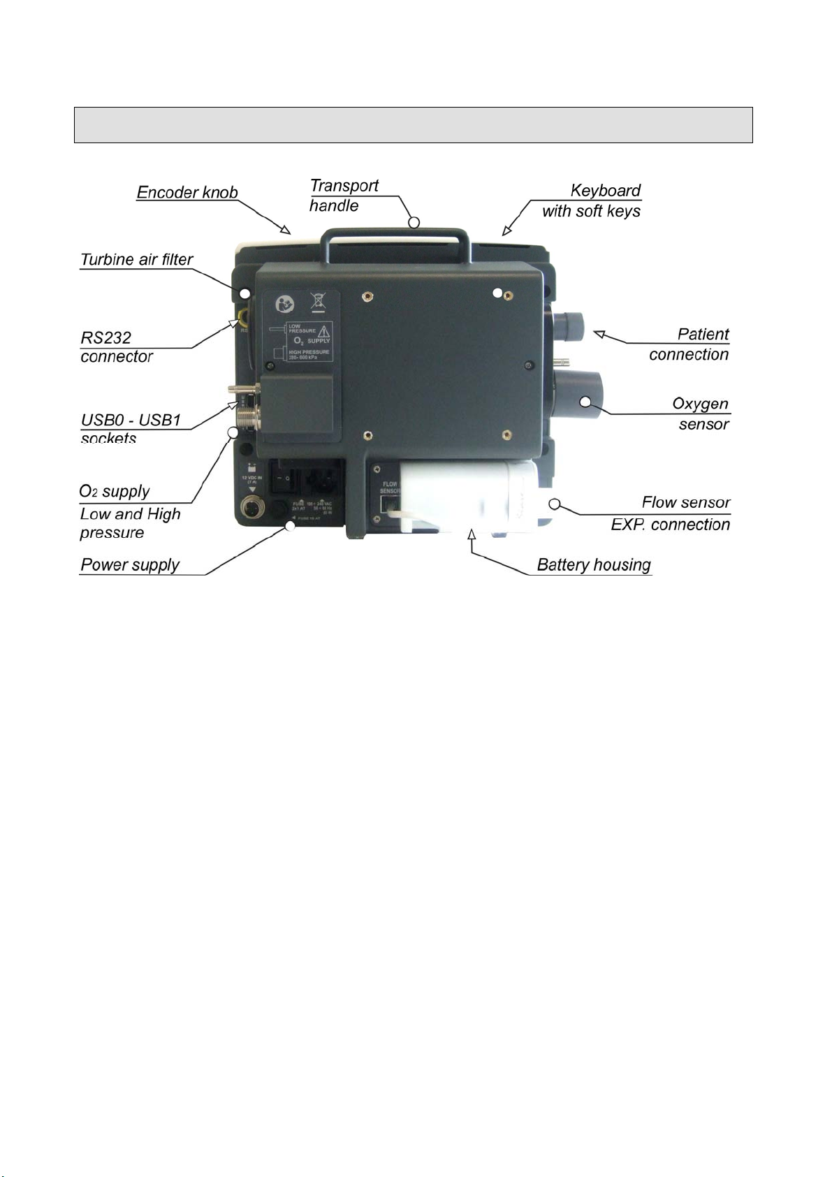
Rear view : Falco 202 Evo ( 10.4” )
see 2.1 Overall view (front, side and rear view)
see 2.1.1 Power supply area
see 2.1.2 Pneumatic area (Oxygen)
see 2.1.3 Patient connections
see 2.2 Touch screen / Keyboard and encoder knob
see 2.3 Lung ventilator description
2-2 User manual, DU3104101
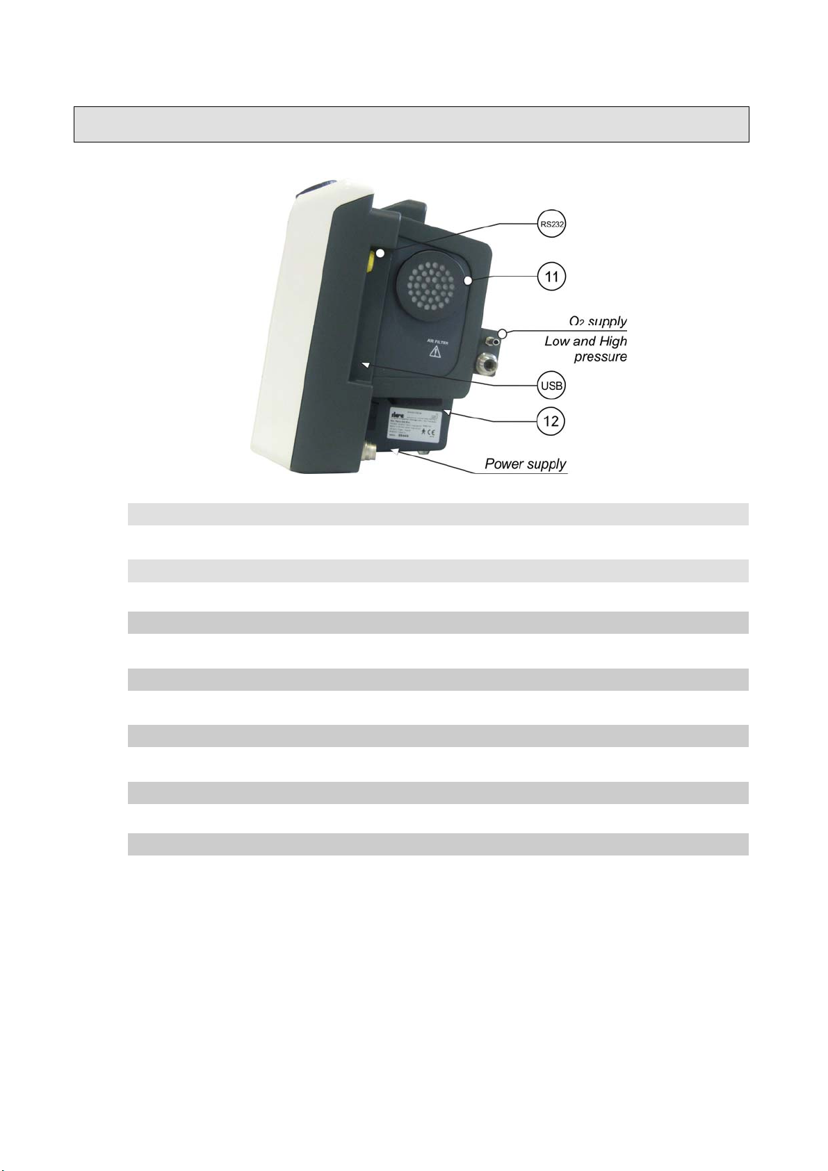
Side view: Falco 202 Evo ( 10.4” )
11 AIR FILTER: turbine air filter
O2 connection (see following chapter)
12 Air intake
RS232 RS-232 (ODU connector) for CO2 sensor connection
USB USB connectors: CPU programming or Trend and Events downloading
Power supply (please, refer to following paragraph)
Falco 202 Evo
2-3
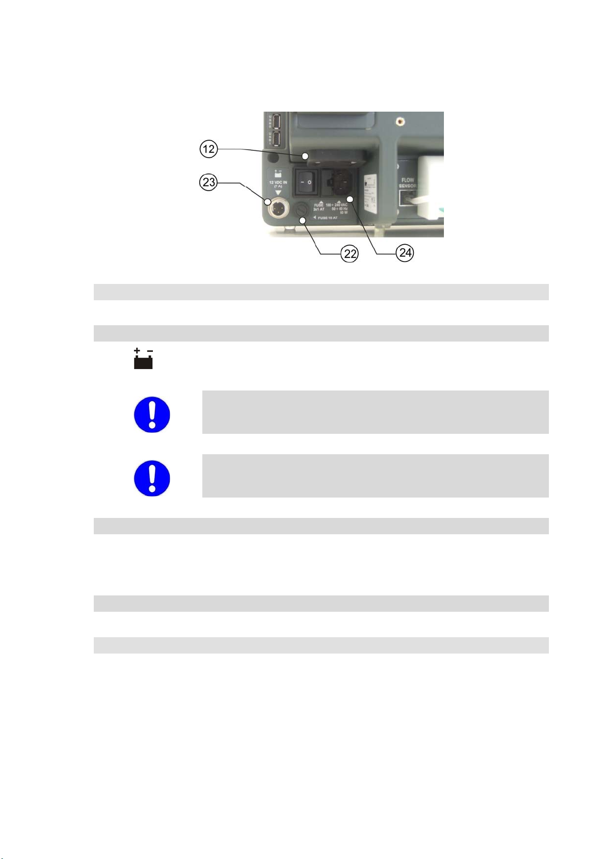
2.1.1 Power supply area
22
23
FUSE 10 AT: safety fuse for battery power circuit (1 x 10 AT)
12 VDC IN (7 A): connector for external 12 Vdc 7A power supply
The external supply voltage can be provided trough a battery or a
supply source having the characteristics above specified.
An external battery used as power source for the functioning of the
Falco 202 Evo become integral part of this medical system.
24 I / O: lung ventilator supply switch
FUSE 2 x 1AT: safety fuses for 220 Vac power supply circuits
100-240VAC 50-60Hz 60VA: plug for mains power supply connection
12 Air intake
2-4 User manual, DU3104101
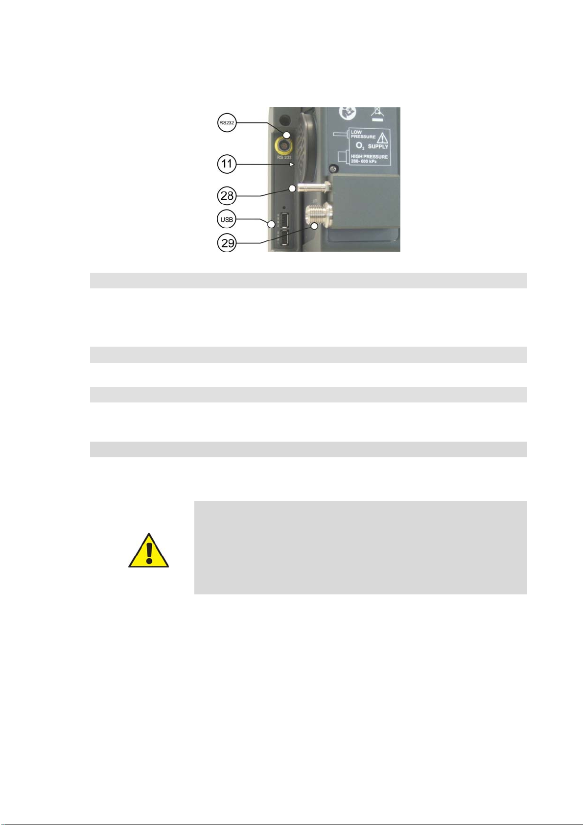
2.1.2 O2 pneumatic area
USB USB sockets for programming.
One USB socket for CPU programming (near the reset button) and one USB
socket for Screen Shoot (for more instructions see on Service Manual).
11 AIR FILTER: turbine air filter
28 LOW PRESSURE: connection for low pressure medical oxygen from a low
pressure source
29 HIGH PRESSURE: connection for high pressure oxygen source
WARNING !!
LOW PRESSURE: the medical O2 low pressure source should have
a maximum flow of 15 l/min.
HIGH PRESSURE: the medical O2 pressure should range from 280
kPa to 600 kPa (2.8 - 6 bar / 40 - 86 psi).
Falco 202 Evo
2-5
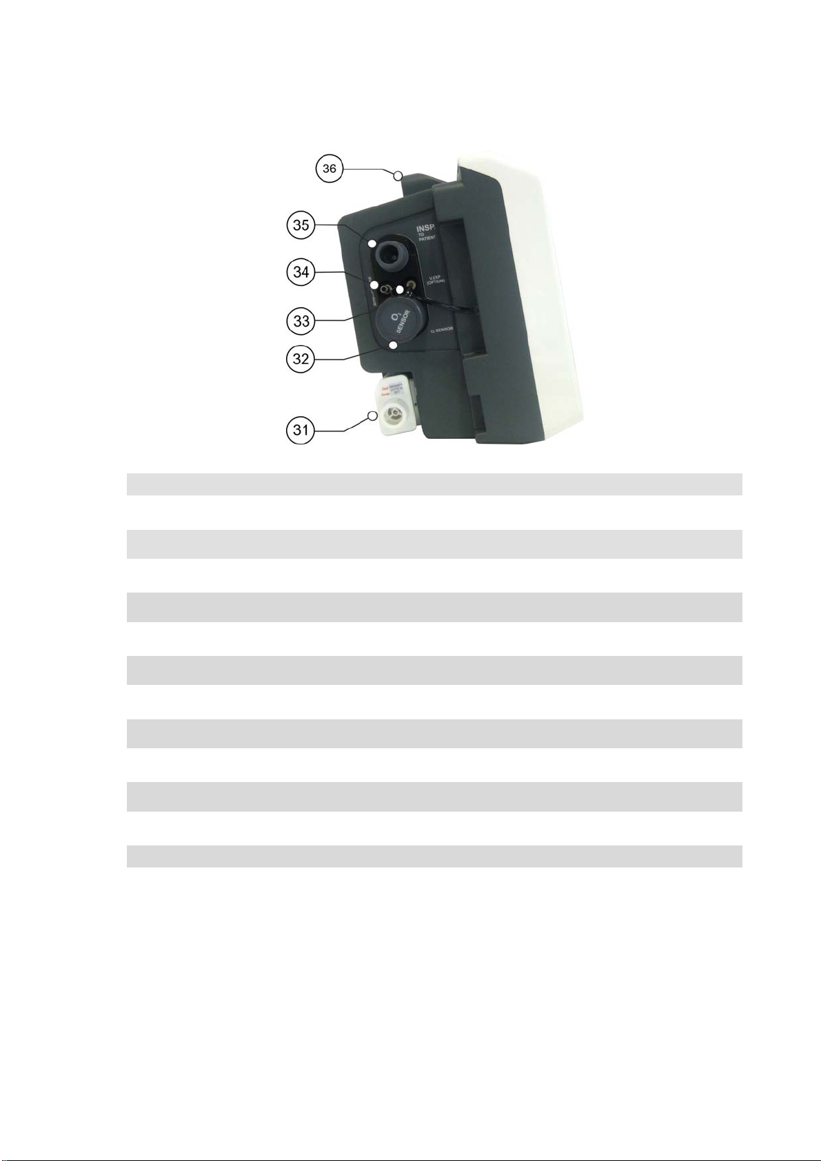
2.1.3 Patient connections
31 FLOW SENSOR: flow sensor placed on expiratory patient line
32 O2 SENSOR: mechanical guard for O2 sensor electrical connection
33 V.EXP (option): unused fitting
34 NEBULIZER: outlet fitting for nebulizer circuit ( 6 l/min )
35 INSP. TO PATIENT: inhalation fitting for patient circuit
36 Transport handle
2-6 User manual, DU3104101
2.2 Touch screen and Keyboard
2.2.1 Touch screen
In electronics a “ touch screen “ is a particular device obtained from the merge of a
display/screen and a digital display, allowing user interaction with a graphic interface by
fingers or particular objects. Therefore, a touch screen is an inlet and outlet device at the
same time.
The touch screen, thanks to its features, can replace the functions of the keyboard with soft
key and encoder knob, and can have, contemporarily, a larger display in the same space
and a direct interactivity between user and device.
Here below some examples on how to use the “touch screen“.
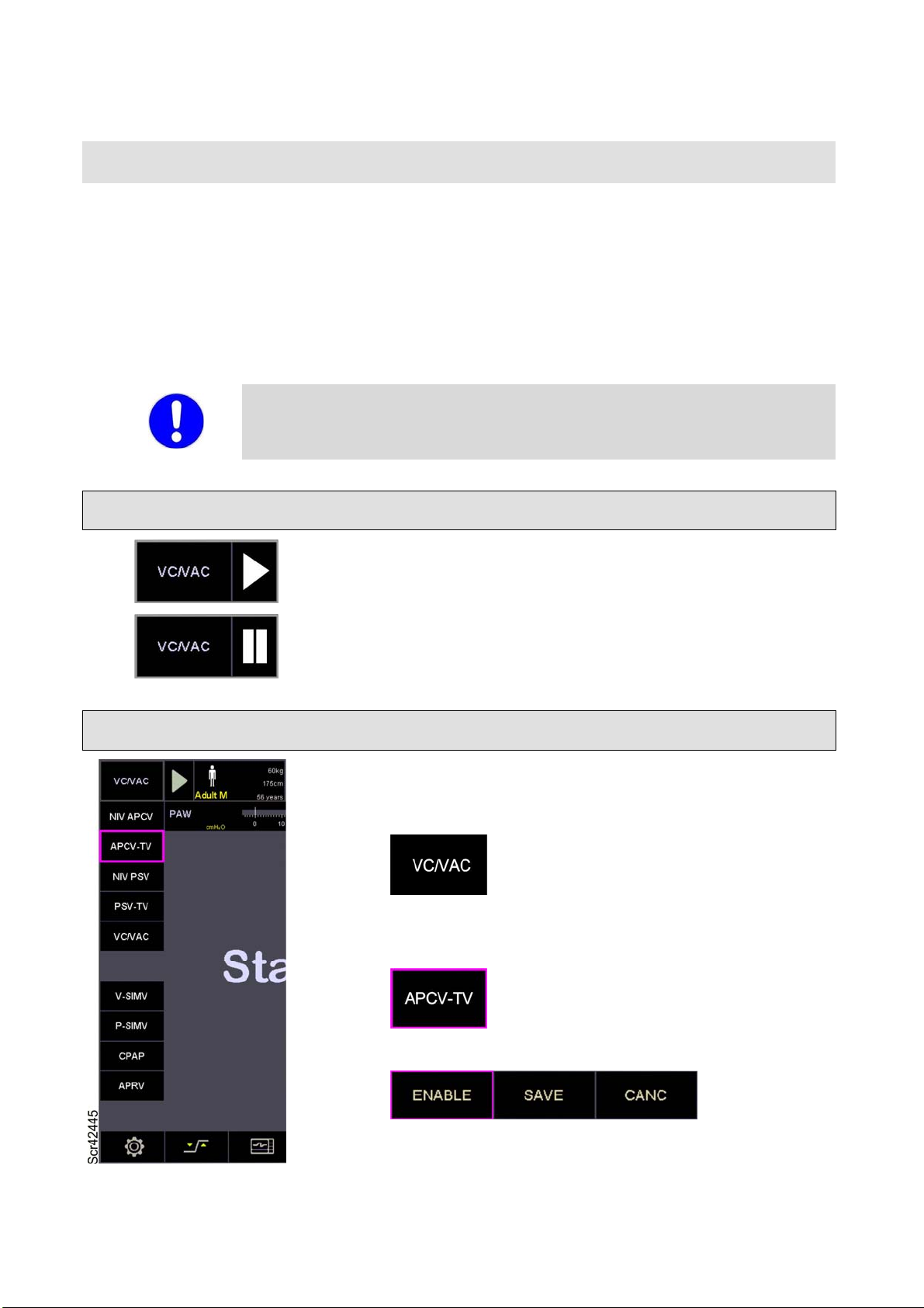
Operative command
Select icon to START ventilation in the selected operative
mode.
Operative mode
Select icon to STOP ventilation; lung ventilator goes to
Stand-by mode.
Select the area indicating Operative Mode
All available operative modes are shown
Select the new operative mode
Confirm the selection
Falco 202 Evo
2-7
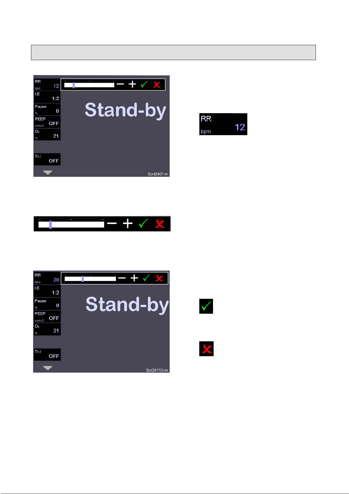
Respiratory parameters set
Select the area indicating the respiratory
parameters to be modified.
The modification bar is displayed.
Select the new parameter’s value on the
bar:
Drag the cursor
Select the icon + or -
Confirm the selection
Cancel
2-8 User manual, DU3104101
 Loading...