

Page 1
OPERATING MANUAL
TW alpha plus
TITRATION SAMPLE CHANGER
Page 2

Gebrauchsanleitung ................................................................................................. Seite 3 … 16
Wichtige Hinweise:
Die Gebrauchsanleitung ist Bestandteil des Prod uktes. Vor der ersten Inbetri ebnahme bitte sorgfältig les en,
beachten und anschließend aufbewahren. Aus Sicherheitsgründen darf das Produkt ausschließlich für die
beschriebenen Zweck e eingesetzt werden. Bitte beachten Sie auch die Gebrauchsanleitungen f ür eventuell
anzuschließende Geräte.
Alle in dieser Gebrauchs anleitung enthaltenen Anga ben sind zum Zeitpunkt der Dr ucklegung gültige Daten.
Es können jedoch vom Hersteller sowohl aus technischen un d kaufmännischen Gründen, als a uch aus der
Notwendigkeit heraus, gesetzliche Bestimmungen d er verschiedenen Länder zu berücksichtigen, Ergän zungen am Produkt vorgenommen werden, ohne dass die beschriebenen Eigenschaften beeinflusst werden.
Operating Manual ..................................................................................................... Page 17 … 30
Important notes:
The operating manual is part of the product. Befor e initial operation, p lease carefully read and obser ve the
operating manual and keep it. For s afet y reasons the product m ay only be used f or the purpos es desc ribed in
these present operating manual. Please also consider the operating manuals for the devices to be connected.
All specifications i n this op erating m anual are guidanc e values which ar e vali d at the t ime of printing. However, for technical or com mercial reasons or in the nec essity to com ply with the statuar y stipulations of various
countries, the manufacturer may perform additions to the product without changing the described properties.
Mode d’émploi ........................................................................................................... Page 31 … 44
Instructions importantes:
Le mode d'emploi fai t partie du produit. Pr ière de lire et d’ observer attentivement le mode d'emploi a vant la
première mise en marc he de l´appare il, et de le cons erver. Pour des raisons de sécur ité, l´appar eil ne pourr a
être utilisé que pour les usages décrits dans ce présent m ode d'emploi. Nous vous prions de res pecter également les modes d'emploi pour les appareils à connecter.
Toutes les indications c om pris es dans c e mode d’emploi sont don nées à titre indicatif au moment de l'impression. Pour des raisons techni ques et/ou commerciales ains i qu'en raison des dispositions lég ales existantes
dans les différents pays, le fabricant se réserve le droit d'effectuer des suppléments concernant l´appareil
pour séries de dilution qui n’influencent pas les caractéristiques décrits.
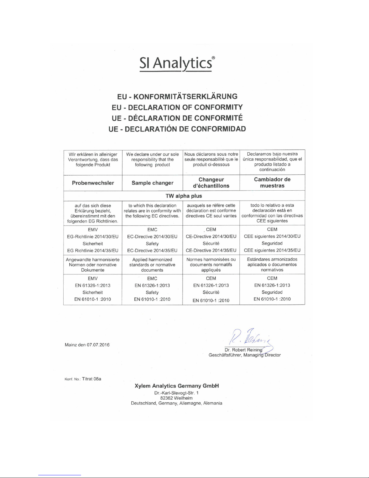
EG – KONFORMITÄTSERKLÄRUNG / EC – DECLARATION OF CONFORMITY
CE – DECLARATION DE CONFORMITE / CEE – DECLARATION DE CONFIRMIDAD
Page 3

CONTENTS
1 Specifications of the TW alpha plus .................................................................. 19
Intended Use .......................................................................................................................... 19 1.1
Technical specifications .......................................................................................................... 19 1.2
2 Set-up and initial operation ................................................................................ 20
Unpacking the device ............................................................................................................. 20 2.1
Warning and safety information .............................................................................................. 20 2.2
Rear view ................................................................................................................................ 21 2.3
System preparation ................................................................................................................ 22 2.4
3 Sample plates of the TW alpha plus .................................................................. 23
4 Built-in magnetic stirrer Built-in magnet i c st ir rer............................................. 23
5 I/O port of the TW alpha plus Titration Sample Changer ................................. 23
General I/O description ........................................................................................................... 23 5.1
Electrical properties of the I/O port ......................................................................................... 23 5.2
Inputs of the I/O port ............................................................................................................... 24 5.3
Outputs of the I/O port ............................................................................................................ 24 5.4
The “Pump-Unit” port .............................................................................................................. 24 5.5
6 Connection to a computerized titration system ............................................... 24
Interface connections ............................................................................................................. 24 6.1
Integration in a daisy-chain ..................................................................................................... 24 6.2
Data-transfer parameters ....................................................................................................... 25 6.3
7 Command list of the TW alpha plus Titration Sample Changer ...................... 26
8 Switch positions .................................................................................................. 28
Baud-Rate ............................................................................................................................... 28 8.1
Plate size ................................................................................................................................ 29 8.2
Address ................................................................................................................................... 29 8.3
9 Guarantee ............................................................................................................ 30
10 Storage and transportation ................................................................................ 30
11 Recycling and Disposal ...................................................................................... 30
Version 181114 US
Page 4

Notes to the Manual
The provided manual will allow you the proper and safe handling of the product. For maximum secur ity,
observe the safety and warning instructions in the operating manual.
Warning of a general danger to personnel and equipment:
Non-compliance results (can result) in injury or material damage.
Important information for device use.
Refers to another part of the operating manual.
Status at time of printing
Advanced technolog y and the high q uality of our products are guaranteed by a continu ous development.
This may result in diff erences between this operating m anual and your product. W e cannot exclude mistakes. We are sure you un derstand that no legal claims can be der ived from the information, illustr ations
and descriptions. A potentially more recent version of this manual is available on our internet website.
The German version is the original version and binding in all specifications.
Copyright
© 2018, Xylem Analytics Germany GmbH.
Reprinting - even as excerpts - is only allowed with the ex plic it wri tten author iza tio n.
Page 5

19
1 Specifications of the TW alpha plus
Intended Use 1.1
Der Titrations-Probenwechsler ermöglicht die Durchführung von Serien-Titrationen mit automatischem
Probenwechsel. Er ist einsetzbar für alle Proben, die in einem offenen Becherglas durchgeführt werden
können. Mit einem dafür geeigneten Titrierkopf lassen sich CSB-Titrationen in den genormten
Reaktionsgefäßen nach DIN 38 409, Teil 41 direkt durchführen. Der Probenwechsler wird über die
RS-232-C-Schnittstellen vom Computer bzw. von Titratoren gesteuert. Er besitzt einen eingebauten
Magnetrührer.
Technical specifications 1.2
Translation of the legally binding German version (Release: 08. november 2018)
CE sign: EMC compatibility according to the Council Directive: 2014/35/EU
applied harmonized standards: EN 61 010-1-1:2010
Low-voltage directive according to the Council Directive 2014/30/EU
Testing basis EN 61 326, Part 1
Country of origin: Made in Germany
Automatic TW alpha plus Titration Sample Changer with interchangeable sample plates.
Sample plates for 12, 24 beaker glasses or 24 COD reaction vessels according to DIN 38 409, Part 41.
48-type plates available as special make.
Stroke height: 270 mm, at delivery ex-factory limited to 130 mm
Beaker glasses for sample plates with 12 samples Order number
(* = preferred shape):
250 ml with muzzle, low shape 21 106 36*
400 ml with muzzle, high shape 21 116 41
400 ml with muzzle, high shape 21 117 41
Beaker glasses for sample plates with 16 samples Order number
(* = preferred shape):
100 ml with muzzle, low shape 21 106 24
150 ml with muzzle, low shape 21 106 29*
250 ml with muzzle, high shape 21 116 36
250 ml without muzzle, high shape 21 117 36
Beaker glasses for sample plates with 24 samples Order number
(* = preferred shape):
50 ml with muzzle, high shape 21 116 17*
50 ml without m u zzle, high shape 21 117 17
Materials:
Device: Casing made of two-component- coated ALU, steel sheet, and epoxy resin
Sample plate: Stainless steel and ABS
Dimensions:
Device: 143 x 620 x 475 mm (W x H x D)
Sample plates: Diameter 450 mm, H = 65 mm (for beaker glasses)
H = 110 mm (for COD reaction vessels according to DIN 38 409, Part 41)
Connection values:
220 V, 30 VA
110 V, 30 VA
Weight
Device: approx. 10.3 kg
Sample plate: with 12 beaker glasses 250 ml: approx 2.7 kg
with 16 beaker glasses 150 ml: approx. 2.6 kg
with 24 beaker glasses 50 ml: approx 2.4 kg
with 24 reaction vessels: approx. 6.3 kg
Page 6

20
2 Set-up and initial operation
Unpacking the device 2.1
The device was carefully tested and packed in the factory.
For the scope of delivery, please refer to the enclosed part list.
Bitte beachten Sie, dass alle Teile restlos aus der Verpackung entnommen werden.
Please make sure to take out all parts from the packing.
The Sample Changer may be set up on any flat surface.
Please plug the mains connection cable com ing with the device to t he cold-device plug ( Europe-type inte-
grated plug) at the back panel. Bef ore s witching on, please ensure th at th e de vic e’s opera t ing vo lt age as set
on the voltage-select or switch at t he bottom of the device m atches the mains v oltage. The pos sible opera ting voltage range is shown on the type plate (p lease refer to the base p late). If the set operating v oltage
does not match the mains voltage, please contact your competent service department.
The device is switched on using th e mains switch loc ated at the back panel, a g reen light at the front pane l
will indicate the “On” operating status.
Warning and safety information 2.2
The device corresponds to protection class II.
It was manufactured and te sted according to DIN EN 61 010, Par t 1, "Protectiv e Measures for elect ronic
measurement devices" and control devices and has left the factory in an impeccable condition as concerns
safety technolog y. In order to m aintain this condition a nd to ensure s afe oper ation, the user shou ld observe
the notes and warning information contained in the present operating instructions. Development and production is done within a system which meets the requirements laid down in the DIN EN ISO 9001 standard.
For reasons of safety, the device and th e po w er s uppl y TZ 1853 must be opened by authorised pers on s
only; this means, for instance, that work on electrical equipment must only be performed by qualified
specialists. In the case of nonobservance of these provisions the device and the power supply may
constitute a danger: electrical accidents of persons or fire hazard. Moreover, in the case of
unauthorised intervent ion in the device or the power supply, as well as in the case of negligently or deliberately caused damage, the warranty will become void.
Prior to switc hing the dev ice on it has to be ensure d that th e operating voltage matc hes the mains vol tage. The operat ing voltage is indicated on the specification plate (Underside of the device and the power
supply). Nonobservance of this provision may result in damage to the device and the power supply,
or in personal injury or damage to property!
If it has to be assumed that safe operation is impossible, the device has to be put out of
operation and secured against inadvertent putting to operation. In this case please switch the device
off, pull plug of the mains cable out of the power supply, and remove the device from the place of work.
Examples for the assumption that a safe operation is no longer possible,
• if the package is damaged,
• if the device shows vis ible damages,
• if the power supply shows visible damages,
• if the device does not function properly,
• if liquid has penetrated into the casing,
• if the device has been altered technologically or if unauthorized personnel tried or succeeded
to open the instrument as attempt to repair it.
In case that the user operates such a device, all thereof resulting risks are on the user.
Page 7

21
Rear view 2.3
Fig. 1 Rear view of the TW alpha plus Titration Sample Changer
1. Stirrer port (low-voltage integrated plug, inner
contact ∅ 2.1 mm).
2. Setting of the stirring speed of the built-in
magnetic stirrer
3 Fastening points for hose and cable carriers
4 Setting of sample plate size being used
( section 7.2)
5 Multi-purpose switch for setting the baud rate,
the mains frequency being applied, and the
“normal” or “COD” s ample containers being used
( section 7.1)
6 Setting of the device address ( section 7.3)
7 Connector for communication with computer
and data communication with titrators, RS-232-C
interface (1) 9-channel D sub miniature socket
( section 5)
8 Connector for data communication with other
peripherals within a daisy chain, RS-232-C interface (2) 9-channel D sub miniature socket
( section 5)
9 Connector for pump and valve modules, 15channel D sub miniature socket ( section 4)
Moreover, the following operating elements are
accessible from the back panel:
Mains connector with fuse
Pump connector: Rinsing device
Mains switch
6
5
2
3
4
7
8
9
Page 8

22
System preparation 2.4
2.4.1 Fitting of a hose carrier
Please use the enclosed k nurled screws to attac h the hose carrier to the bore holes provided for th is purpose on the back panel.
When fastening the hoses and e lectrode cables after wards, please avoid an y kinking of the hoses and cables during this process
2.4.2 Changing the stroke height
The ex-factory setting of the stroke height is approx. 130 mm (half of the travel). It is possible to mechanically change the strok e height using an internal s witch. If very high containers are to be used, for instance,
COD containers, the connection of the middle switch is to be interrupted. If the stroke height is to be
modified, the casing has to be opened in any case. T o do so, please pull off the titration-head c arrier, then
remove the four screws al ong the front guidance ke y as well as the two upper and the two lat eral ones at
the bottom. After rem oving the entire enclosure, the middle switch can be foun d to the left of the guidance
body.
Do not change the setting of the upper limit switch since it is used to limit the travel.
2.4.3 Connection of a titration system
A data cable type TZ 308 4 is used to connect the TW alpha plus Titration Sample Chang er to a titration
system, or with a type TZ 3088 direc tly to a computer. This is done us ing th e upp e r of the 9-channel sock ets
on the back panel, i. e. the (1) RS-232-C data comm unicat ion interf ace. For f urther inf orm ation, please r efer
to section 6.
2.4.4 Electrodes, titration tips, stirrer
The required electrodes and titrat ion tips are to be inserted into the cor responding bore holes ( NS 14,5) of
the titration head, e.g. of the no. TZ 1463 t ype. If a s tirrer is used, it sh ould als o be conn ected to one of the
bore holes. The power su pply of the st irrer is establ ished via a cabl e which is to be attached to the titration
head and leads to the “Rührer/Stirrer” socket at the back panel of the TW alpha plus Titration Sample
Changer.
The stirring speed can be adjusted by soft ware comm ands. The m ax. rps of the built-in magnetic stirrer can
be limited using the potent iometer on the back panel. If you wish that the m ax. stirring sp eed be adjust able
through an RS command, the potentiometer is to be set to stage 9.
Page 9

23
3 Sample plates of the TW alpha plus
Four sample plates are available for the TW alpha plus Titration Sample Changer:
TZ 1452 sample plate: 12 samples 250 ml low shape, 400 ml high shape
TZ 1459 sample plate: 16 samples 100 ml to 150 ml, high and low shape, 250 mm high shape
TZ 1454 sample plate: 24 samples 50 ml, high shape
TZ 1444 sample plate: 24 samples COD reaction vessel accordin g to DIN 38 409, Part 41
Sample plate : 48 samples Available as a special version upon request.
On the back panel of the TW alpha plus Titration Sample Changer there is a stage switch inscribed
“Proben/Samples” ( Fig.1, Pos. 4). This switch is us ed to communicate the sample plates used to the
Sample Changer. Using a small screw driver, this switch can be set to the corresponding size.
Here is: 0 = 12 samples
1 = 16 samples
2 = 24 samples
4 = 48 samples
This setting can also be made via software us ing the appropriat e comm ands from a connec ted com puter or
titration device ( section 7).
The sample plates are set on clock-wise according to the mark engraved on the sample changer. The
connection with the Sample Changer is made b y simply placement on the c orresponding driving cone. I n
this process, the sample plate is to be rotated until it latches. To remove the sample plate, just lift it a little bit
up.
4 Built-in magnetic stirr er Buil t-in magnetic stirrer
The Sample Changer is equipped with a built-in magnetic stirrer. If the TitroLine® 7000, 7750 and 7800 or a
PC Software is used, for instance, this stirrer can be switched on and off via the RS-232-C interface 1.
At the start of titration, the speed set in the method wil l be transferred. The stirrer will start running at that
speed. When setting the stirring speed, please do not select any setting below 10 seconds.
It the stirring speed is to be contro lled by the titra tion unit, pl ease make sur e that the settin g knob is set to
full stirring speed, other wise t he m ax. poss ible stirri ng speed will be lim ited in acc ordance with the s tage s et
on the setting knob. The desired stirrin g speed can then be fine-adjusted using the rotar y knob on the back
panel of the sample changer.
5 I/O port of the TW alpha plus Titrati on Sam ple Changer
General I/O description 5.1
The TW alpha plus T itration Sample Chan ger is equipped with a 15-channe l plug connector f or connecting
pump and valve modules . T his I/O port c an be us ed to c onnect the avai lable devic es via a c able ( Fig. 1,
item. 9). T his I/O port is controlled b y the computer software. A tot al of 4 outputs and 5 inputs is avai lable.
For the required commands, please refer to the command list ( section 7).
Electrical properties of the I/O port 5.2
The in- and outputs of the I/O port are galvanically isolated from the electronics of the titration sample
changer by optocouplers of the HCPL-0700 type. No direct circuiting of power consumers is possible.
The pump and valve m odules available f rom SI Anal ytics
can be co nnected dire ctly to the I/O unit us ing a
cable.
Page 10

24
Inputs of the I/O port 5.3
A maximum current of 20 mA may be applied to the 4 inputs of the I/O port. An opt ocoupler of the HCP L0700 type is being us ed. Circuiting has to be such tha t + 5V are appl ied to the comm on anode and the i nputs can be activated by contact to ground. The pin configuration is shown in the list below:
Input Pin number
1 1
2 2
3 3
4 4
Common anode (+ 5 V connection) 13
The statuses of the inp uts c an be inquir ed using th e “aaIP” c omm and. The ans wer is: “aaI =101100 00”. The
order of the zeroes and o nes r eflects the logic s tate of the inputs . T he firs t digit is assigne d to the f irst input.
Only the four first bit are of any relevance; for system reasons, the last 4 bits are always 0.
Outputs of the I/O port 5.4
The outputs of the I/O port are configured as follows:
Output Pin number
1 9
2 10
3 11
4 12
Common emitter 14 and 15
Common power supply 13
The supply voltage f or the optoc oupl er out puts has to be m ade fr om an ex ternal sourc e and am ounts to between 1 and + 18 V. Max. output current of the HCPL-0700 optocoupler module: 60 mA.
The “Pump-Unit” port 5.5
This port, located on the back panel the device, is used to c ontrol a connected p ump (e.g. of the no. T P 20
type) or valve. The bu ilt in relay is able to control a voltage of 220 V and a current of 2 A. The <aaCE>
command will switch the port on, the <aaCA> will switc h it off again. The <aaCS1..9 > command will switch
the port on for the specified time, with the number indicating the time in terms of seconds.
6 Connection to a computerize d ti t ra t ion system
I nt erf ace co n nect io ns 6.1
The TW alpha plus Titration Sample Chang er is equipped with two serial inter faces (RS-232-C) for data
communication with other devices. The plug con nectors for these inter faces are located o n the back panel
of the device ( Fig. 1, item. 7 and 8). The upper soc ket establishes the connection towards a com puter,
whereas the lower socket connects to other devices.
The transfer parameters can be set using the “Baud Rate” switch ( Fig. 1, item. 5).
Integration in a daisy-chain 6.2
Using a device address will enable you to operate more tha n one titration devices in the form of a daisychain. Use an RS-232-C cable to connect the computer with the first device in the chain (e.g. with a
TITRONIC
®
500 plus Piston Burette). Using another c able, connect the second RS-232-C interf ace of the
burette to the upper RS-232-C interface (1) of the Sample Changer. From the second (lower) RS-232-C
interface (2) of the Sample Changer, it is possible to connect additional devices ( Fig. 1, item. 7 and 8).
Page 11

25
Please m ake sure that the devices in the c hain have different addres ses assigned. T he device address
of the TW alpha p lus Titration Sample Chang er can be set on the b ack panel of the device. T he address
range is from 00 to 15, depending on the 0 to F switch position. The “3” address is usually defaulted.
When us ing the devic e with a Titrator TitroL ine® 7000, 7750 or 7800, the sample chang er mus t always
be connected directly downstream of the titration unit.
In this case the R S interface 2 of the last device (Titrator or Piston Burette) is to be set to the 7; 2; no
parameter record. After setting the RS interface, this device must be restarted.
Data-transfer parameters 6.3
The transfer speed of the interfaces can be set using the “Baud Rate” switch ( Fig. 1, item. 4).
Except for the transfer speed, the following parameters are defaulted:
Number of data bits = 8
Number of stop bits = 1
parity check = even, odd, no
The “Baud Rate” switch can be used to set a total of 2 different speeds:
4800 baud, 9600 baud. The ex-factory setting of the baud rate is 480 0.
In addition to the baud rate, this sw itch c an be us ed to adap t the d ev ice to the mains fr equenc y (50 H z or 60
Hz) and to specify the use of a COD sample plate. The list below shows the details of the switch positions:
Switch Position Meaning
0 4800 Baud / even Parity / 50 Hz / normal beaker glasses
1 4800 Baud / odd Parity / 50 Hz / normal beaker glasses
2 4800 Baud / no Parity / 50 Hz / normal beaker glasses
3 9600 Baud / no Parity / 50 Hz / normal beaker glasses
4 4800 Baud / even Parity / 60 Hz / normal beaker glasses
5 4800 Baud / odd Parity / 60 Hz / normal beaker glasses
6 4800 Baud / no Parity / 60 Hz / normal beaker glasses
7 9600 Baud / no Parity / 60 Hz / normal beaker glasses
8 4800 Baud / even Parity / 50 Hz / COD reaction vessels according to DIN 38 409, Part 41
9 4800 Baud / odd Parity / 50 Hz / COD reaction vessels according to DIN 38 409, Part 41
A 4800 Baud / no Parity / 50 Hz / COD reaction vessels according to DIN 38 409, Part 41
B 9600 Baud / no Parity / 50 Hz / COD reaction vessels according to DIN 38 409, Part 41
C 4800 Baud / even Parity / 60 Hz / COD reaction vessels according to DIN 38 409, Part 41
D 4800 Baud / odd Parity / 60 Hz / COD reaction vessels according to DIN 38 409, Part 41
E 4800 Baud / no Parity / 60 Hz / COD reaction vessels according to DIN 38 409, Part 41
F 9600 Baud / no Parity / 60 Hz / COD reaction vessels according to DIN 38 409, Part 41
When using the TW alpha plus T itration Sample Changer in combinat ion with devices from SI Analytics
,
the baud rate is to be set to 4800 including t h e ap propriate options (50 / 60 H z, no rmal beaker glasses/COD
reaction vessels).
Extract from the table:
Switch position Meaning
2 4800 Baud / no Parity / 50 Hz / normal beaker glasses
6 4800 Baud / no Parity / 60 Hz / normal beaker glasses
A 4800 Baud / no Parity / 50 Hz / COD reaction vessels according to DIN 38 409, Part 41
E 4800 Baud / no Parity / 60 Hz / COD reaction vessels according to DIN 38 409, Part 41
Page 12

26
7 Command list of the TW alpha plus Titration Sample Changer
The TW alpha plus T itration Sample Changer f eatures a set of commands whic h can be used to control it
from connected devices . These commands ar e generated automatic ally by titration units fr om SI Analytics
and the various titration s ystems. If you wish to create applica tion programs of your own, please use t he
commands listed below.
All commands are present in the following form: Address (2 digits) command CR LF.
The address is used to addres s the proper device, s ince it is possible t hat more than one de vice having an
addressable RS-232-C interface are connected to a computer. The addresses may be selected from 00
through 15. In the list below the addresses are indicated by the generalised “aa” form.
Command Response Reply from the TW alpha plus
aaGT Query of the set plate size aaPlatezz
zz means any digits
aaKH Lift titration head up to upper limit switch aaY
aaKR Lower titration head, aaY
if no beaker glass is present: aaERROR:KEIN B ECHER
(NO BEAKER)
aaKGzzz Lower titration head by the specified percentage aaY
of the total travel (zzz = 1 to 100)
aaKUzzz Raise titration head by the specified percentage aaY
of the total travel (zzz = 1 to 100)
aaDV Rotate plate forwards by one position aaY
aaDR Rotate plate backwards by one position aaY
aaDT Move plate to next titration position aaY
(used following the “DCzz” command)
aaDPzz Move plate to the indicat ed pos it ion aaY
(zz = 1 up to max plate position)
aaDCzz Rotate plate to specified position. aaY
The initial position will be stored and serves as information
for the next titration position (-> “aaDT” command)
(zz = 1 to max. plate position)
aaPTNzz Switch plate size to size specified in zz.. aaY
Stroke height for normal beaker height.
(zz = 12; 16; 24; 48)
aaPTCzz Switch plate size to size specified in zz. aaY
Stroke height COD glasses.
aaPO Output of current plate position aaPOSITIO N = zz
Page 13

27
Command Response Reply from the TW alpha plus
aaQE The built-in stirrer port and aaY
the built-in stirrer will be switched on
aaQA The built-in stirrer port and aaY
the built-in stirrer will be switched off
aaQSz Setting the stirring speed aaY
(z = 0 bis 9)
aaRH Device identification aaIdent: TW280
aaON witch all 4 outputs on aaY
aaOJ witch all 4 outputs off aaY
aaOE1..4 Switch specified outputs on (1 to 4) aaY
Separate digits by ‘;’, example: aaOE1;3;4
aaOA1..4 Switch specified outputs off (1 to 4) aaY
Separate digits by ‘;’, example: aaOA1;2;3
aaOM1..4 The specified outputs will be monitored b y
the inputs specified in the “aaOI” command
Separate digits by ‘;’, example: aaOM2;4
aaOI1..4 The selected outputs will switch off the aaY
inputs specified in the “aaOM” command if
“low” status is present
Separate digits by ‘;’, example: aaOI3;4
aaOT Monitoring of the inputs is switched on. aaY
aaIP Query of all inputs of the I/O port, only the aaI=10110000
4 first digits are relevant
aaWA This command has no effect, but is aakeine Daten
continued for compatibility reasons
aaWO This command has no effect, but is aaY
continued for compatibility reasons
aaVE Query of the built-on software version number aaVersion: MMM TT JJ
aaCA The built-in Pump-Unit port is switched off aaY
aaCE The built-in pump unit is switched on aaY
aaCS1..9 The built-in Pump-Unit port is switched on aaY
for the specified period of time (in s)
Page 14

28
Command Response Reply from the TW alpha plus
aaRB Check for presence of a beaker glass aaY
if no beaker glass is present: aaERROR:KEIN BECHER
aaRC Repeat last command; however, the last „last command “
command will not be executed again
aaDQ Rotate plate by one position, irrespective of the head position aaY
aaSH Immediate stop of all processes and movements aaY
aaSC Continue all processes and movements
which were stopped with the aaSH command aaY
aaSR Immediate stop of all processes and movements; aaY
all processes and movements are reset to basic state
99AAzz Serial numbering of all devices within the daisy-chain
The first device in the chain will be assigned the zz address. The next
following device will get the zz+1 addres s .
If zz=15, the next device will be assigned the zz=1 address
All devices respond with their new address zzY
99AB.. Send any command to all devices
all devices will respond to the command specified after <99AB>
Example: 99ABVE will return the version numbers of all connected devices.
8 Switch positions
Baud-Rate 8.1
The “Baud Rate” switch ( Fig. 1, item. 5 ) is used to set the trans fer speed, the m ains frequenc y, and the
beaker glasses being us ed. The switch position mus t only be changed if the TW alpha plus Titration Sam ple
Changer is switched of f. The mains frequenc y has an effec t on the motiona l speed of the t itration head. T o
ensure the proper control of the movements of the titration head by the software, the mains frequency has to
be set correctly. The indic ation of “normal beaker glass”, “COD reaction vess el” has an influence on the
“Lower head” command: Since the COD reaction vessels are considerably higher than normal beaker
glasses, the movement of the titration head has to stop earlier.
Switch position Meaning
0 4800 Baud / even Parity / 50 Hz / normal beaker glasses
1 4800 Baud / odd Parity / 50 Hz / normal beaker glasses
2 4800 Baud / no Parity / 50 Hz / normal beaker glasses
3 9600 Baud / no Parity / 50 Hz / normal beaker glasses
4 4800 Baud / even Parity / 60 Hz / normal beaker glasses
5 4800 Baud / odd Parity / 60 Hz / normal beaker glasses
6 4800 Baud / no Parity / 60 Hz / normal beaker glasses
7 9600 Baud / no Parity / 60 Hz / normal beaker glasses
8 4800 Baud / even Parity / 50 Hz / COD reaction vessels according to DIN 38 409, Part 41
9 4800 Baud / odd Parity / 50 Hz / COD reaction vessels according to DIN 38 409, Part 41
A 4800 Baud / no Parity / 50 Hz / COD reaction vessels according to DIN 38 409, Part 41
B 9600 Baud / no Parity / 50 Hz / COD reaction vessels according to DIN 38 409, Part 41
C 4800 Baud / even Parity / 60 Hz / COD reaction vessels according to DIN 38 409, Part 41
D 4800 Baud / odd Parity / 60 Hz / COD reaction vessels according to DIN 38 409, Part 41
E 4800 Baud / no Parity / 60 Hz / COD reaction vessels according to DIN 38 409, Part 41
F 9600 Baud / no Parity / 60 Hz / COD reaction vessels according to DIN 38 409, Part 41
Page 15

29
When using the TW alpha plus Titration Sample Cha nger in combination with th e Titrator TitroLine® 7000,
7750 or 7800 the baud rate should nor mall y be set to 4800. T he list below gives the possible param eters of
the mains frequency and the COD plates:
Switch position Meaning
2 4800 Baud / 50 Hz / normal beaker glasses
6 4800 Baud / 60 Hz / normal beaker glasses
A 4800 Baud / 50 Hz / COD reaction vessels according to DIN 38 409, Part 41
E 4800 Baud / 60 Hz / COD reaction vess els accor d ing t o DIN 38 409, Part 41
Considering t hat the position of this s witch is only read in during po wer-up of the device, the sam ple
changer is to be s witched off prior to a ny change of the s witch position, a nd to be switched on again after
the position of the switch has been changed.
Plate size 8.2
The plate size being used is set using the “Proben/Samples” switch ( Fig. 1, item. 4) on the back panel of
the TW alpha plus Titr ation Sample Changer. The switc h has 16 positions, of which onl y the first 4 are in
use. The switch positions have the following meaning:
Position Number of samples
0 12
1 16
2 24
3 48
Consider ing that the position of th is switch is only read in d uring power-up of the device, the sample
changer is to be s witched off prior to a ny change of the s witch position, a nd to be switched on again after
the position of the switch has been changed
Address 8.3
The TW alpha plus T itration Sample Cha nger is equipped with a n addressable ser ial interface. To mak e a
clear distinction betwee n all the conn ected devices, a n address is preced ing each comm and. This address
is always made up of 2 di gi ts and s tretc hes in t he ran g e from 00 to 15. The addre s s set us ing a c orr espondingly marked switch ( Fig. 1, item. 6). The switch position correspond to the following addresses:
Position Address
0 00
1 01
2 02
3 03
4 04
5 05
6 06
7 07
8 08
9 09
A 10
B 11
C 12
D 13
E 14
F 15
The “3” address is usually defaulted for operation with the Titrator TitroLine
®
7000, 7750 or 7800.
Considering that the posit ion of this switch is onl y read in during power-up of the device, the sam ple
changer is to be s witched off prior to a ny change of the s witch position, a nd to be switched on again after
the position of the switch has been changed.
Page 16

30
9 Guarantee
We provide guarantee for the device described for two years from the date of purchase. This guarantee
covers manufacturing faults being disco vered within the m entioned period of two years. Claim under guarantee covers only the restoration of functionality, not any further claim for damages or financial loss.
Improper handling/us e or i llegit imat e open ing of the d evice results in loss of th e guarant ee r ights . The g uarantee does not cover w ear par ts , as lob es , cylinders, valves a nd pip es inc lu din g t he t hr ead c onn ectio ns an d
the titration tips. T he breach of glass parts is also excluded. To ascertain the guarantee liability, please
return the instrument and proof of purchase together with the date of purchase freight paid or prepaid.
10 Storage and tr a nspor t a t ion
If the TW alpha plus Titration Sample Changer has to be stored over som e tim e, or t o be d isloc at ed, t he us e
of the original packing wil l be the best protection of the devices . However, in many cases th is packing will
not be available an ymore, so that one will have to compose an equivalent packaging system. Sealin g the
lower section in a foil is her eby recommended. The d evice should be stored in a room with a temperature
between +10 and +40°C, and the (relative) humidity of the air should not exceed 70 %.
11 Recycling and Disposal
Please observe the applicable local or national regulations concerning the disposal of “waste
electrical and electronic equipment”
The TW alpha plus Titration S ample Changer and his packaging are manufac tured as far as pos sible from
materials which can be d ispos ed of en viro nmental-friendly and recycled in a technical l y appr opri ate manner.
If you have any question regarding disposal, please contact the service (see backside of this manual).
Page 17

Page 18

Page 19
Page 20

Typ / type/ type / tipo TW alpha plus
Bescheinigung des Herstellers
Wir bestätigen, dass ob en genanntes Gerät gemäß DIN EN ISO 9001, Absatz 8.2.4 „ Überwachung und
Messung des Produk ts“ geprüf t wurde un d dass die fe stgelegte n Qual itätsanfor derungen a n das Pr odukt
erfüllt werden.
Supplier’s Certificate
We certify that the above equipm ent has been tested in accordance with DIN EN ISO 9001, Part 8.2.4
"Monitoring and measurem ent of product" and that th e s pec if ied quali t y requir ements for the product have
been met.
Certificat du fournisseur
Nous certifions que le pro duit a été vérifié selo n DIN EN ISO 9001, parti e 8.2.4 «Surveillance et mesure
du produit» et que les exigences spécifiées pour le produit sont respectées.
Certificado del fabricante
Certificamos que el aparato arriba mencionado ha sido controlado de acuerdo con la norma
DIN EN ISO 9001, secc ión 8.2.4 «Seguim iento y medición d el product o» y que c umple c on los requis itos
de calidad fijados para el mismo.
Hersteller
(Manufacturer)
Xylem Analytics Germany GmbH
Dr.-Karl-Slevogt-Str.1
82362 Weilheim
Germany
SI Analytics
Tel. +49(0)6131.66.5111
Fax. +49(0)6131.66.5001
E-Mail: si-analytics@xyleminc.com
www.si-analytics.com
Service und Rücksendungen
(Service and Returns)
Xylem Analytics Germany Sales GmbH & Co.KG
SI Analytics
Gebäude G12, Tor Rheinallee 145
55122 Mainz
Deutschland, Germany
Tel. +49(0)6131.66.5042
Fax. +49(0)6131.66.5105
E-Mail: Service-Instruments.si-analytics@xyleminc.com
SI Analytics is a trademark of Xylem Inc. or one of its subsidiaries.
© 2018 Xylem, Inc. Version 181114 US 602 877 3
 Loading...