

Page 1
TitroLine®
7500 KF
TITRATOR
OPERATING INSTRUCTIONS
Page 2

Gebrauchsanleitung ...................................................................................................... Seite 5 ..... 72
Wichtige Hinwei se: Die Gebrauchsanlei tung vor der ersten Inbetriebnahm e des Tit rators TitroLine® 7500 KF
bitte sorgf älti g lesen und beac hten. Aus Sic herhei tsgrü nden darf der T i trator TitroLine
®
7500 KF ausschließlich
nur für die in dieser Gebr auc hsanl eitung beschriebenen Zwecke ei ngesetzt werden.
Bitte beachten Si e auc h die Gebrauc hsanl eitungen für die anzuschließenden Geräte.
Alle in dieser Gebr auc hsanl eitung enthalt enen A ngaben sind zum Zeitpunkt der Drucklegung gül tige Daten. Es
können jedoch von SI Analytics sowohl aus technischen und kaufmännischen Gründen, als auch aus der
Notwendigkeit heraus, gesetzliche Bestimmungen der verschiedenen Länder zu berücksichtigen,
Ergänzungen am Titrator TitroLine
®
7500 KF vorgenommen werden, ohne dass die beschriebenen
Eigenschaften beeinflusst werden.
Operating Instructions ................................................................................................ Page 73 .... 142
Important notes: Before initial operation of the Titration Unit TitroLine® 7500 KF, please read and observe
carefully the oper ating i nstructions. F or safety reasons the Titrati on Unit TitroLine
®
7500 KF may only be use d
for the purposes described i n these present oper ating instructions.
Please also observ e the operating instructions for t he units to be connected.
All specifications in this instruction manual are guidance values which are valid at the time of printing.
However, for techni cal or commercial reasons or in the neces sity to comply with the statuary stipulati ons of
various countri es, SI Analyti cs may perf orm additions to the Ti tration Unit TitroLine
®
7500 KF without changing
the described properties.
Page 3

Page 4

TABLE OF CONTENT PAGE
1 . Technical Specifications of the Titrator TitroLine® 7500 KF ................................ 75
1.1 Summary ............................................................................................................................ 75
1.2 Specifications Titrator TitroLine® 7500 KF............................................................................ 76
1.3 Warning and safety inf ormati on ........................................................................................... 79
2 . Unpacking and First Operation .............................................................................. 80
2.1 Unpacking ........................................................................................................................... 80
2.2 Installation and Connection of the TM 235 KF titration stand and t itration vessel .................. 80
2.3 Connecting the Titrator - Com bination with Accessories and Additional Dev ic es .................. 84
2.3.1 Back panel of the titr ator TitroLine® 7500 KF ...................................................................... 84
2.3.2 Connection port s of the Ti troLine® 7500 KF ........................................................................ 84
2.3.3 Connecting a print er ............................................................................................................ 84
2.3.4 Connecting a USB devi c e (manual controller, keyboard, memory device, hub) .................... 84
2.3.5 Connection of analy tical balances ....................................................................................... 85
2.4 Setting the Language of the Country ................................................................................... 85
2.5 Interchangeable unit WA ..................................................................................................... 86
2.5.1 Installing the interchangeable unit ....................................................................................... 86
2.6 Positioning and Replacing an Interchangeable Uni t ............................................................. 87
2.6.1 Placing an interc hangeable unit ........................................................................................... 87
2.6.2 Removing an interc hangeable unit ...................................................................................... 88
2.6.3 Programming the ti tration unit .............................................................................................. 88
2.7 Initial Filling or Rinsing of the Entire Interchangeable Unit .................................................... 90
2.8 Filling the titr ation vessel with solvent .................................................................................. 92
2.9 Replacing the Glass Cylinder and the PTFE Piston ............................................................. 92
3 . Working with the Titrator TitroLine® 7500 KF ........................................................ 95
3.1 Front Keyboard ................................................................................................................... 95
3.2 Display ................................................................................................................................ 95
3.3 Manual controller “mouse“ ................................................................................................... 96
3.4 External PC Keyboar d ......................................................................................................... 96
3.5 Menu Structur e ................................................................................................................... 97
3.6 Main Menu .......................................................................................................................... 99
3.6.1 Standard methods of KF Titration ........................................................................................ 99
3.6.2 Automatic KF Titration ....................................................................................................... 100
3.6.3 Dosage ............................................................................................................................. 104
3.6.4 Preparing Soluti ons ........................................................................................................... 107
4 . Method Parameters................................................................................................ 108
4.1 Method editing and new m ethod ........................................................................................ 108
4.2 Default methods ................................................................................................................ 108
4.3 Copy Methods ................................................................................................................... 109
4.4 Delete Methods ................................................................................................................. 109
4.5 Print method ..................................................................................................................... 110
4.6 Change Method Param eters.............................................................................................. 110
4.6.1 Method type ...................................................................................................................... 110
4.6.2 Result ............................................................................................................................... 111
4.6.3 Titration param eters .......................................................................................................... 119
4.6.4 Titration end ...................................................................................................................... 122
4.6.5 Dosing parameter.............................................................................................................. 124
4.6.6 Sample identification ......................................................................................................... 125
4.6.7 Documentation .................................................................................................................. 126
5 . System settings ..................................................................................................... 127
5.1 Interchangeabl e Unit - Reagents ....................................................................................... 127
5.2 RS232 Settings ................................................................................................................. 129
5.3 Date and Time .................................................................................................................. 131
5.4 Password .......................................................................................................................... 131
Page 5

5.5 RESET.............................................................................................................................. 131
5.6 Printer ............................................................................................................................... 132
5.7 Device Information ............................................................................................................ 132
5.8 System Tone ..................................................................................................................... 132
5.9 Software Update ............................................................................................................... 133
6 . Data Communication via RS232- and USB -B interface ...................................... 135
6.1 General Information .......................................................................................................... 135
Meaning / Descri ption ........................................................................................................................ 135
6.2 Chaining multiple devices —“Daisy Chain Concept“ .......................................................... 135
6.3 Instructi on S et f or RS-Communication ............................................................................... 135
7 . Connection of Analytical Balances and Printers ................................................ 137
7.1 Connection of Analytical Balances ..................................................................................... 137
7.1.1 Balance TZ-Number .......................................................................................................... 137
7.2 Balance data edit or ........................................................................................................... 138
7.3 Connection of Printers ....................................................................................................... 139
8 . Maintenance and Care of the TitroLine® 7500 KF ............................................... 140
9 . Storage and transportati on ................................................................................... 141
10 Recycling and Disposal ......................................................................................... 141
11 Index ....................................................................................................................... 142
Version 120829 US
Page 6

75
Chapter 1 – Specifications Titrator TitroLine® 7500 KF
1 Technical Specifications of the Titrator TitroLine® 7500 KF
1.1 Summary
The TitroLine® 7500 KF is suitable for the foll owing applications:
The possible range of titrations includes volumetric KF and Dead stop titrations with a maximum of 50
memorisable methods.
The examples of possible use of the TitroLine
®
7500 KF include:
− KF tit r ations with 1-component KF reagents
− KF tit r ations with 2-component KF reagents
− Dead stop ti t r ations such a bromine number and sulphur dioxide in
− Compatible with TitriSoft 3.0.
In addition, the Tit r oLine® 7500 KF comes with following functionalities of the TITRONIC® 500 piston burette:
− Dosing
− Preparation of solutions
Each method allows for the setting of a variety of dosing and filling rat es.
Solutions to be used:
Virtually, any li qui ds and soluti ons wit h a vi scosity of < = 10 mm² / s such as conce ntrat ed sulphuri c aci d m ay
be used. However, one has to avoi d the use of chemicals that may attack glass, PTFE or FEP or that are
explosive, such as hydrofluoric acid, sodium azide or bromine! Suspensions containing high solids
percentages may clog or ev en dam age the dosing syst em .
General pr ov isions:
The safety guidelines that are applicable to the handling of chemi c als have to be observed under all
circumstances. This applies in particular to inflammable and/or etching liquids.
Guarantee
We provide guarantee for the device described for two years from the date of purchase. This
guarantee covers manufacturing faults being discovered within the mentioned period of two years.
Claim under guarantee covers only the restoration of functionality, not any further claim for damages
or financi al loss .
Improper handling/use or illegitimate opening of the device results in loss of the guarantee rights.
The guarantee does not cover wear parts, as lobes, cylinders, valves and pipes including the thread
connections and the titration tips. The breach of glass parts is also excluded. To ascertain the
guarantee liability, please return the instrument and proof of purchase together with the date of
purchase freight paid or prepai d.
Page 7
76
Chapter 1 – Specifications Titrator TitroLine® 7500 KF
1.2 Specifications Titrator TitroLine® 7500 KF
Status July. 01th 2012
CE sign:
EMC compatibility acc or ding to the Council Directive: 2004/108/EG;
applied harmoniz ed standar ds: E N 61326-1:2006
Low-voltage di r ectiv e ac c or ding to the Council Directive 2006/95/EG
Testing basis EN 61 010, P art 1
Country of origin: Germany, Made in Germany
The following solv ents/titration reagent s are allowed to be used:
− All c ommon ti tration solutions.
− As reagent water and al l non-aggressiv e non-organic and organi c fluids are al lowed. If using combustible
fluids fir e please adhere t o the Guidelines for Explosion Protec tion and Prevention of the chemical industr y .
− For f luids wit h higher v iscosity (≥ 5 mm
2
/s), lower boiling poi nt or affinity to outgas, t he filling and dosage
speed can be adjusted.
− Fluids with viscosity over 20mm
2
/s ca nnot be dosed.
Measurement i nput: Karl-Fischer (Dead-stop) connect or for double platinum electrode
Polarisation voltage variably adjustable from 40 … 220 mV.
Connector: 2 x 4 mm - sockets.
Measurement
range
Display resoluti on
Measurement
accuracy* withou
t
sensor probe
I [µA]
0 ... 100
0,1
0,2 ± 1 Digit
* The measurement uncert ainty of the sensor probe has to be taken into acc ount as well.
Page 8

77
Chapter 1 – Specifications Titrator TitroLine® 7500 KF
Display: 3.5 inches -1/4 VGA TFT display with 320x240 pixels.
Inputs: Measurement i nput µA: (Dead-Stop-) connector for double platinum electrode
Connection sockets: 2 x 4 mm)
Power supply: power supply 90-240 V; 50/60 Hz , power input: 30 VA
RS232-C Interface: RS232-C int erface separated galvanically through photocoupler
Daisy Chain function available.
Data bits: adjustable, 7 or 8 Bit (default: 8 Bit)
Stop bit: adjustable, 1 or 2 Bit (def ault: 1 Bit)
Start bit: static 1 Bit
Parity: adjustable: ev en / odd / none
Baud rate: adjustable: 1200, 2400, 4800, 9600, 19200 (Default 4800 baud)
Address: adjustable, (0 to 15, default: 01)
RS232-1 for computer, input Daisy Chain
RS232-2 devices of SI Analytics, titr ator TitroLine
6000/7000/7500,
- Burettes TITRONIC
500, TITRONIC 110 plus, TITRONIC universal,
- Balances of the types Mettler, Sartorius,
- Kern, Ohaus (for m or e, please contac t SI Analytics)
- Exit Daisy Chain
USB Interface: 2 x USB-type A and 1 x USB-ty pe B
USB –Typ B (“slave“) for connecting a PC
USB –Typ A (“master“) for connecting:
- USB keyboard
- USB printer
- USB “mouse“ (“mouse“),
- USB data media e.g. USB stick
- USB Hub
Stirrer/pump TMKF: 12V DC out, 500mA
power supply for sti r r er TM 235 and KF titration stand TM 235 KF
Housing material : Polypropylene
Front keyboard: polyester coated
Housing dimensions: 15.3 x 45 x 29.6 cm (W x H x D), height incl. interchangeable unit
Weight: ca. 2.3 kg for basic unit
ca. 3.5 kg for complete devic e inc l. interchangeable unit (with em pty r eagent bottle)
Ambient conditions: Ambient temperature: + 10 ... + 40 °C for operation and storage
Humidity according to EN 61 010, Part 1:
Max. relative humi dity 80 % for temperatures up to 31 °C,
linear decrease down to 50 % relative humidity at a temperatur e of 40 °
Page 9

78
Chapter 1 – Specifications Titrator TitroLine® 7500 KF
Status Aug. 23
rd
2011
Interchangeabl e un its
Compatibility: units are compatible to the titrat or s TitroLine
®
6000, TitroLine® 7000, TitroLine®
7500 KF and Piston Burette TITRONIC
®
500
Recognition: automatically through RFID. Recognition of unit size and characteristics of the
Titration- or dosi ng sol ution
Valve: volume neutral cone v alv e made fr om fluor oc ar bon poly mers (PTFE), TZ 3000
Cylinder: borosilic ate glass 3.3 (DURAN
®
)
Hoses: FEP hose set, blue
Bracket for supply bott le: suitable for square glas s bottle and misc. reagent bottles
Materials: borosilicat e glass DURAN
®
, fluorocarbon pol ymers (PTFE), stainless steel,
polypropylene,
Dimensions: 15 x 34 x 22.8 cm (W x H x D) incl. reagent bottle
Weight: approx. 1.2 kg for int er c hangeable unit WA incl. empty reagent bottle
Dosing accuracy: after DIN EN ISO 8655, part 3
Accuracy: 0.15 %
Precision: 0.05 - 0.07 %
(Depending on the used int er c hangeable unit)
Dosing accuracy of the Titrator TitroLine
®
7500 KF with WA interchangeable units:
Interchangeable.
unit
type No.
Volume
[ml]
Tolerances of t he Øi
of the glass cylinder
[mm]
Dosage error*
according to
100 % volume
[%]
Reproducibility
[%]
WA 0 5 5.00 ± 0.005 ± 0.15 0.07
WA 1 0 10.00 ± 0.005 ± 0.15 0.05
WA 2 0 20.00 ± 0.005 ± 0.15 0.05
WA 5 0 50.00 ± 0.005 ± 0.15 0.05
Page 10

79
Chapter 1 – Specifications Titrator TitroLine® 7500 KF
1.3 Warning and safety information
The TitroLine® 7500 KF corresponds to prot ection cl ass II. It was manuf actured and tested according to DI N
EN 61 010, Part 1, Protective Measures for El ectronic Measurement Devices and has left the fact ory in an
impeccabl e condition as concerns safet y technology. In order t o maintain this condi tion and to ensure safe
operation, the user should observe the notes and warning information contained in the present operating
instructi ons. Development and production i s done within a system which meets the requi rements lai d down in
the DIN EN ISO 9001 standard.
For reasons of saf ety, the ti trat or TitroLine
®
7500 KF must be open ed by aut hori sed person s only; thi s means,
for instance, that work on electrical equipment must only be performed by qualified speciali sts.
In the case of nonobservance of t hese provisions the titrator TitroLine® 7500 KFmay co nstitute a
danger: electrical accidents of persons or fire hazard. Moreover, in the case of unauthorised
intervention in the titrator TitroLine
®
7500 KF as well as in the case of negligently or deliberately
caused damage, the warranty will become void.
!
Prior to switchi ng the dev ice on i t has to be en sured that the operati ng v oltage of the t itrator TitroLine® 7500
KF matches the mains voltage. The operating voltage is indicated on the specification plat e. Nonobservance of
this provision may result in damage to the titrator TitroLine® 7500 KF or in personal injury or damage to
property.
If it has to be as sumed that safe oper ation is im possible, the tit rator TitroLine
®
7500 KF has to be put out of
operation and secur ed against inadvertent putting to operation. In this case please switch the t itrator TitroLine
®
7500 KF off, pul l plug of the mains cabl e out of the mains socket, and rem ove t he titrator TitroLine
®
7500 K F
from the place of work.
Examples for the assumption that a safe operation is no longer possible,
the package is damaged,
the titrator TitroLine
®
7500 KF shows visible damages,
titrator TitroLine
®
7500 KF does not function properly,
liquid has penetrated into the casing.
The titrator TitroLine
®
7500 KF must not be stored or operated in humid rooms.
For reasons of saf ety, t he tit rator TitroLine
®
7500 KF m ust onl y be used f or the range of appl i cation descri bed
in the present operati ng instructions.
In the case of dev iations from the intended proper use of the device, it is up to the user to evaluate the
occurring risks.
!
T he relevant reg ulations reg arding the h andling of th e substan ces used have to b e observed: The
Decree on Hazardou s Matters, the Chem icals Act, and the rul es and inform ation of the chemical s trade. It
has to be ensured on t he side of the u ser that the persons entr usted with the u se of the titr ator TitroLine
®
7500 KF are experts in the handli ng of substances used in the envir onment and in titrat or TitroLine
®
7500 KF
or that they are supervi sed by speci alised persons, respectively.
During all work with tit r ation solutions:
!
Please wear protective gl asses! !
The titrator TitroLine
®
7500 KF i s equipped with int egrated circuit s (EPROMs). X rays or other high energy
radiation may penetrate through the device’s casing and del ete the program.
For working with liquids, not beeing common titration solvents, especially the chemical resistance of the
construction m aterials of the t itrator TitroLine
®
7500 KF hav e to be considered (pl ease also refer to chapter
1.1).
For the use of liqui ds with hi gh vapour pressure or (mixture of) substance s not being m enti oned in chapt er 1.1
as allowed substances, t he safe and proper op erati on of the tit rator TitroLine
®
7500 KF has to be guaranteed
by the user.
When the piston moves upwards withi n t he cyli nder, a mi crofilm of dosing li qui d or titrati on solution wil l al ways
remain adhered to t he inner wall of the c ylinder, but t his has no i nfluenc e on the dosing acc uracy. T his small
residue of li quid, however, may ev aporate and t hus pe netrat e i nto t he zone underneat h the piston, and if nonadmitted liqui ds are being used, the m aterials of t he titrator TitroLine
®
7500 KF may be dissolved or c orroded
(please refer al so to c hapter 8 “Maintenance and Care of the titrator Titr oLine
®
7500 KF”).
Page 11
80 Chapter 2. Unpacking and First Operation
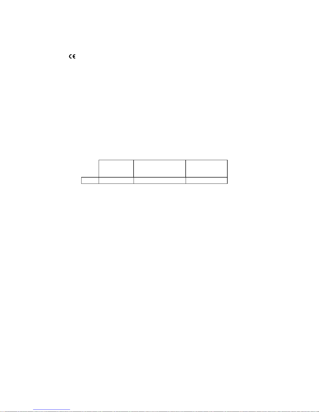
2 Unpack i ng an d Fir st Operation
2.1 Unpacking
The titrator it self as well as all r elated accessory and peripheral parts hav e been c ar efully checked at the factory
to ensure their cor r ect function and size. The TitroLine
®
7500 KF modules consists of:
• TitroLine
®
7500 basic unit
• An interchangeable dosing unit WA 05, WA 10 or WA 20
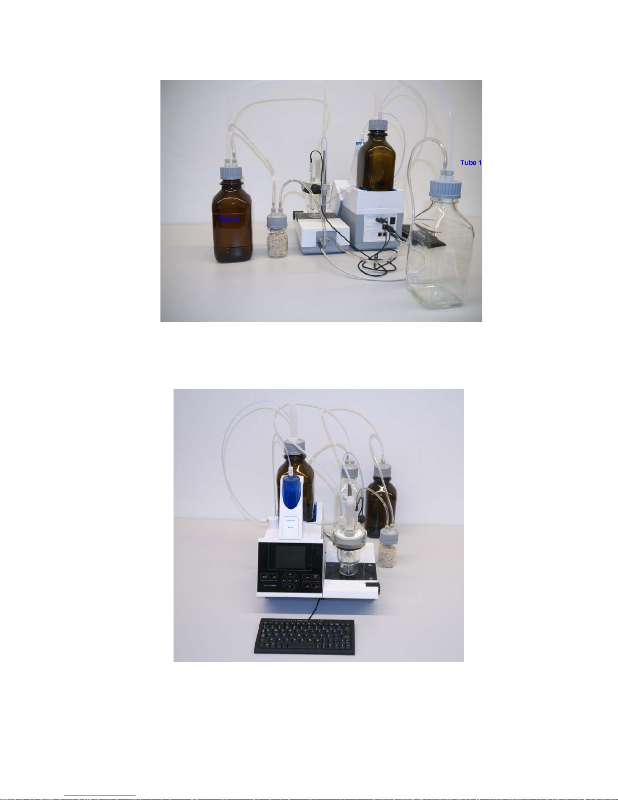
• The KF titration stand (pump and stirrer) TM 235 KF including waste (1 L clear bottle), solvent (1 L amber
bottle) and moisture bottle (100 ml) with all tubes.
• Titration vessel TZ 1770 including titration tip
• KF starter kit TZ 1789 with molec ular sieve, glass wool and a set of syringes with needl es.
• Electrode KF 1100
Please ensure that the sm all ac c essories are also removed in full from the packaging. For the scope of delivery,
please refer to the enclosed parts lists.
Fig. 1
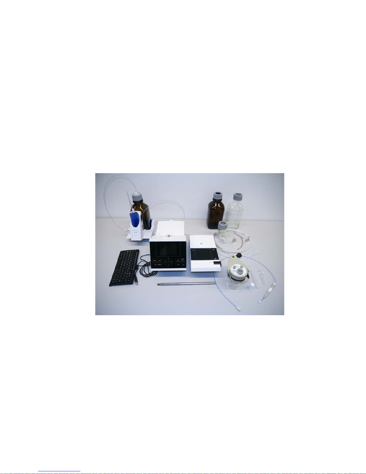
2.2 Installation and Connection of the TM 235 KF titration stand and titration vessel
The titrator TitroLine® 7500 KF and the TM 235 KF may be placed on any flat surface.
As a rule, the TM 235 KF titration stand is arranged to the right of the titrator.
The pump/stirrer is connected to the 12V out-socket at the rear panel of the TitroLine
®
7500 KF using the TZ
1577 connection cable (scope of delivery of the basic device) (cp. ‘B ac k panel ’ illustration, chapter 2.4) .
The stand rod (scope of deliv er y of t he basi c device) is screwed into the thread of the TM 235 KF.
The titrati on v essel TZ 1770 is mount ed at the stand rod. Please take care that the m etal clam p is adj usted as
shown in the attached photo:
Page 12
81
Chapter 2. Unpacking and F ir s t O per ation
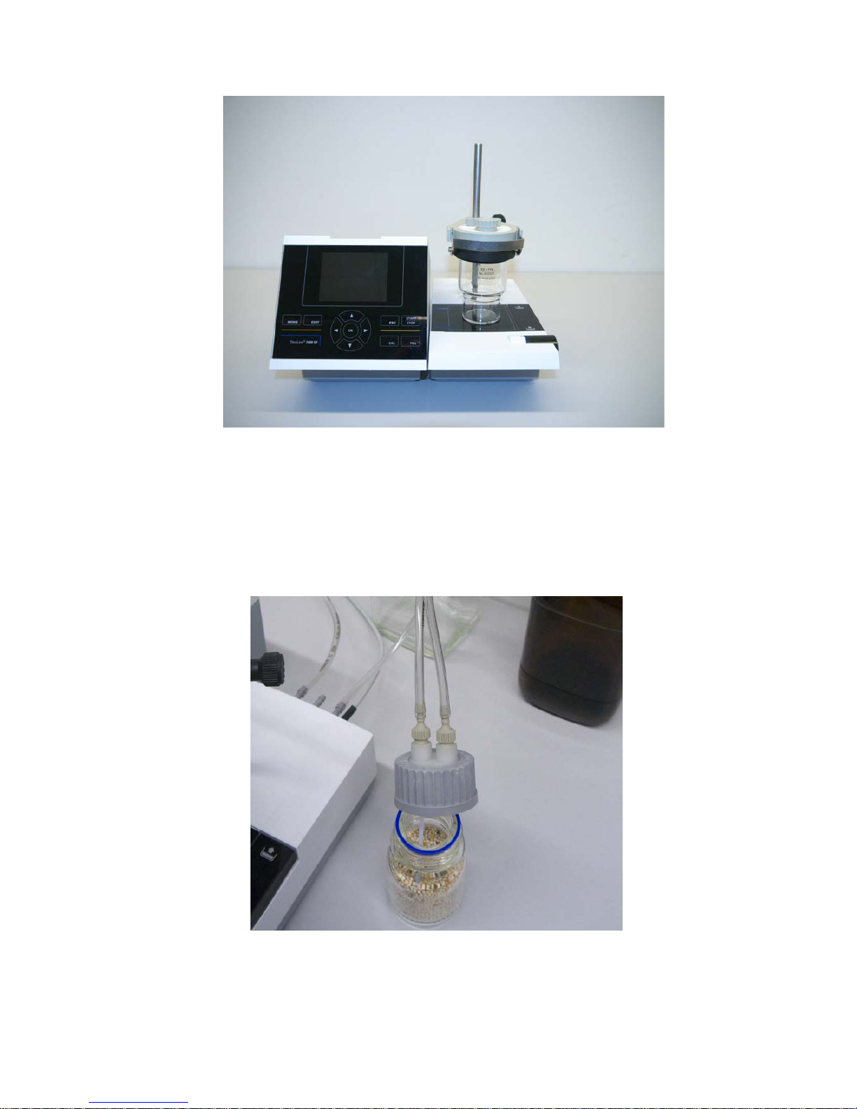
Fig. 2
Put all three white inner plastic adapters at the waste, solvent and moisture bottle.
Fill the moisture bottle with molecular sieve.
Connect the PVC and PTFE plastic tubes as shown in the next pictures.
The PVC tubes are connected t o the connectors at the back side of the TM 235 KF. The long PVC tube is used
for the connecti on of t he waste bott le. The two shorter PVC ones are used to connect the moisture bottle and the
solvent bottle.
Fig. 3
Page 13

82 Chapter 2. Unpacking and First Operation
The moisture bot tle is connected to the right connect or (view from above) of the TM 235 KF. The waste (clear)
bottle is connect ed to the left connector.
Fig. 4
The PTFE tube from the clear waste bottle is adjusted to the ground (tube 1) of the tit r ation vessel. The PTFE
tube from the solvent bottle (tube 2) is adjusted as shown in the next two pictures:
Fig. 5
Page 14
83
Chapter 2. Unpacking and F ir s t O per ation
Fig. 6
The burette tip is placed into the left NS 14 opening and connected to the valve of the interchangeable unit.
Put first some glass wool and then molecular sieve in the plastic moisture tube. Place it t o the ot her NS opening
as shown in the next picture.
Fig. 7
The electrode KF 1100 i s connected to the µA input.
The keyboard is connected to one of the USB –A ports.
Page 15
84 Chapter 2. Unpacking and First Operation
2.3 Connec ting the Titrator - Combination with Accessories and Additional Devices
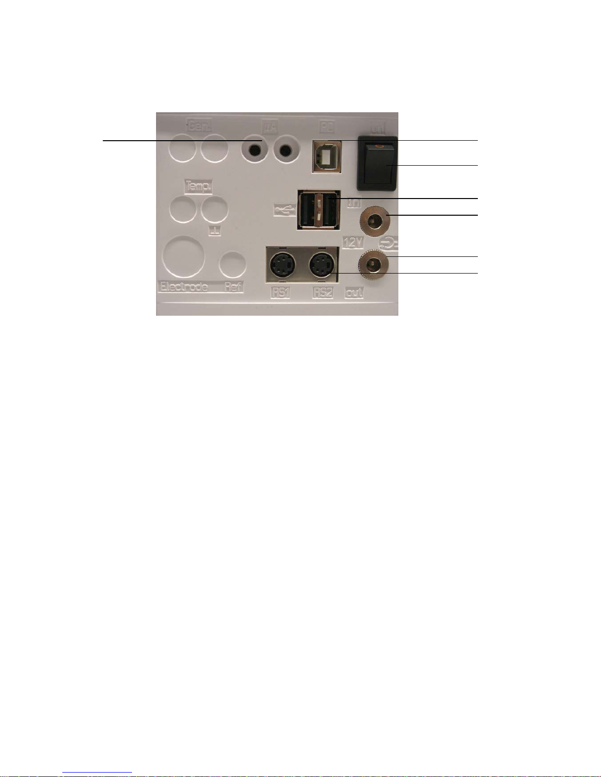
2.3.1 Back panel of the titrator TitroLine® 7500 KF
Fig. 8
2.3.2 Connection ports of the TitroLine
®
7500 KF
The TitroLine® 7500 KF is equipped with the following connections:
1) µA measurem ent input for the connection of doubl e platinum electrodes (KF 1100 or Pt 1200, Pt 1400)
2) USB-B interface for connection to a PC
3) On/Off switch
4) Two USB-A (“M aster “ ) interfaces for connecting USB devices such as a keyboard, printer, manual control
unit, USB memory devic e etc.
5) ”in“ : Connection of the external power pack
6) “out“: Connection of the TM 235 KF titration stand or TM 235 magnetic stirrer
7) Two RS232 ports, 4-channel (Mini-DIN):
RS1 for connection to the PC
RS2 for connection of a weighing balance and other devices from SI Analytic s (burettes a.s.o.)
2.3.3 Co nn ect ing a printer
Printers with a USB int erface are to be connected to one of the two USB-A interfaces. These pri nters have to
feature HP PCL emulation (3, 3GUI, 3 enhanced, 5, 5e). So-called GDI printers cannot be used!
Alternatively the thermo-compact printer Seiko S 445 c an be connect ed.
2.3.4 Co nn ect ing a USB device (manual controller, keyboard, memory device, hub)
The following USB devi c es can be connec ted to the USB-A interfaces:
• PC-keyboard
• TZ 3880 manual controller (in the following: ”mouse“)
• Printer
• USB stor age dev ices, e.g. USB sticks
• USB hub
• USB bar c ode scanners
1
2
3 4 5
6
7
Page 16
85
Chapter 2. Unpacking and F ir s t O per ation
2.3.5 Connection of ana ly t ic al balances
Analytical balanc es are t o be c onnec ted to the RS232-2 using an appropriate cable
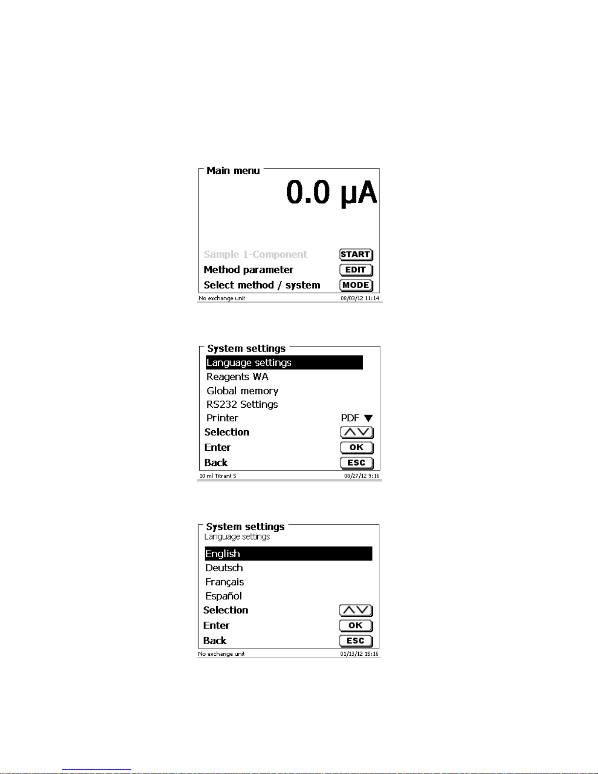
2.4 Setting the Language of the Country
The ex-factory default language setting is English. When the piston burette is switched on, the mai n menu will
appear once the boot sequence is completed:
Fig. 8
Using <SYS/<F7> or <MODE>, followed by <System settings> you navigate to the system settings. The very first
menu is to be used for setting t he language of the country:
Fig. 9
Use <ENTER>/<OK> to call the menu. S elec t t he national language using the <↑↓> arrow keys, confi rm it with
<ENTER>/<OK>:
Fig. 10
The selected language wil l appear immediately. Pressing the <ESC> key twice will return the user to the main
menu.
Page 17
86 Chapter 2. Unpacking and First Operation
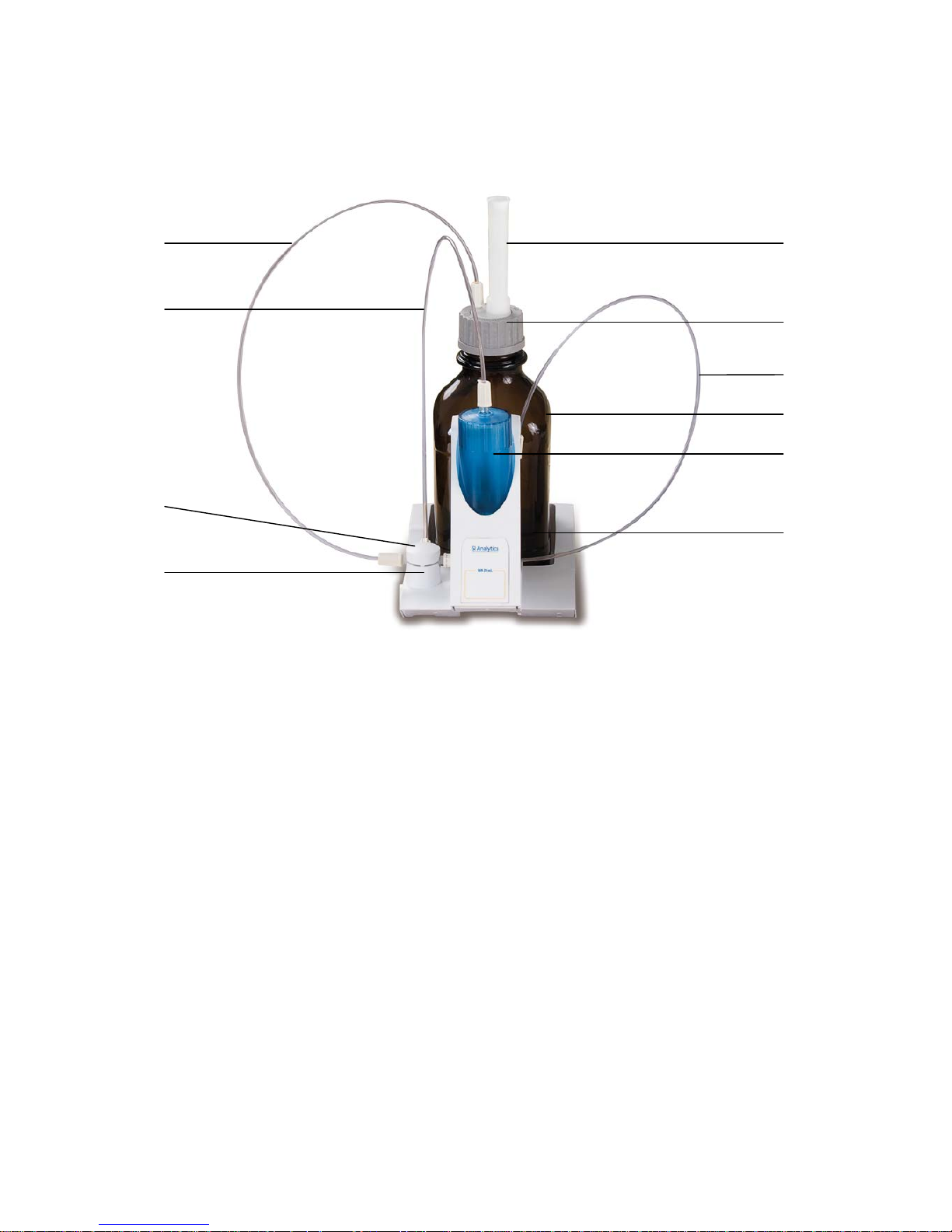
2.5 Interchangeable unit WA
Fig. 11
1) TZ 3871 - sucti on hose
2) TZ 38 72 - connection hose
3) TZ 3873 - dosing hose wit hout dosing tip and holding bracket;
TZ 3874 - dosing hose with dosing tip and holding bracket
4) TZ 3801 - valve cov er lid
5) TZ 3000 - 3/2-way valve
6) TZ 2003 - drying t ube
7) TZ 3802 - threaded c ap with borehole GL 45, incl. adapter with 2 openings for drying tube and suction
hose
8) TZ 3803 - 1 litre reagent bottle, brown
9) TZ 3900 - UV protecti on, blue transparent
10) TZ 3875 - shaft for titration tip and
TZ 3356 - titrati on tip unit, blue or micro titration tip white TZ 3285, adapter TZ 1525
11) TZ 1507 - plastic drip-down tubule
2.5.1 Installing the interchangeable unit
Fig. 11 shows a completely assembled interchangeable unit.
• Remove the valve with the attached hoses from the pack, and then push it on the valve support until it
snaps in position.
• Slip on the valve cover lid on the valve as is shown in the ill ustr ation.
• Insert the TZ 3872 connection hose in the threaded hole prov ided in the burette cylinder, and then tighten
it by hand.
• Insert the TZ 3871 suction hose into the threaded openi ng of t he GL 45 or S 40 adapter s, and then
tighten it manually.
• Remove the standard dosing hose TZ 3874 from the valve and c onnec t t he dosi ng hose i nc luding from
the KF titrati on vessel TZ 1770
6 3 1 2 4 5 7 8 9
11
Page 18
87
Chapter 2. Unpacking and F ir s t O per ation
2.6 Positioning and Replacing an Interchangeable Unit
The base unit comes with an RFID r eader , and all the interchangeable units are equi pped with an RFID
transponder. Thi s tr ansponder can be use d to store the following information:
• Uni t size (cannot be changed)
• Uni t ID (cannot be changed)
• Reagent name (default: blank)
• Concent r ation (default: 1.000000)
• Concent r ation determined on: (Date)
• To be used until: (Date)
• Opened/Produced on: (Date)
• Test ac c or ding to ISO 8655: (Date)
• Charge description: (default: no c har ge)
• Last modification: (Date)
Each time an interc hangeable unit is pushed onto the base unit, t he data is automatically read out of the
transponder.
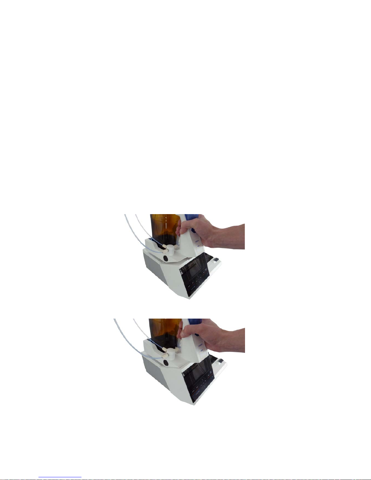
2.6.1 Placing an interchangeable unit
The interchangeabl e unit is to be placed on the device unit as is shown in fig. 12 a-c; subsequentl y , it is to be
pushed downwards until the black button latches on the left side.
Fig. 12.a
Fig. 12.b
Page 19
88 Chapter 2. Unpacking and First Operation
Fig. 12.c
2.6.2 Remo ving an interchangeable uni t
Removing the int erchangeable unit is done in reverse order:
• Depress the black button on the left, and then pull the interchangeable unit forward as is shown in fig. 12
c – 12 a.
!
Please note: Removing the interchangeable unit is only possible as long as the piston is in the lower
position (zero position). Possibl y, i t may be necessary to press the <FILL> key first.
!
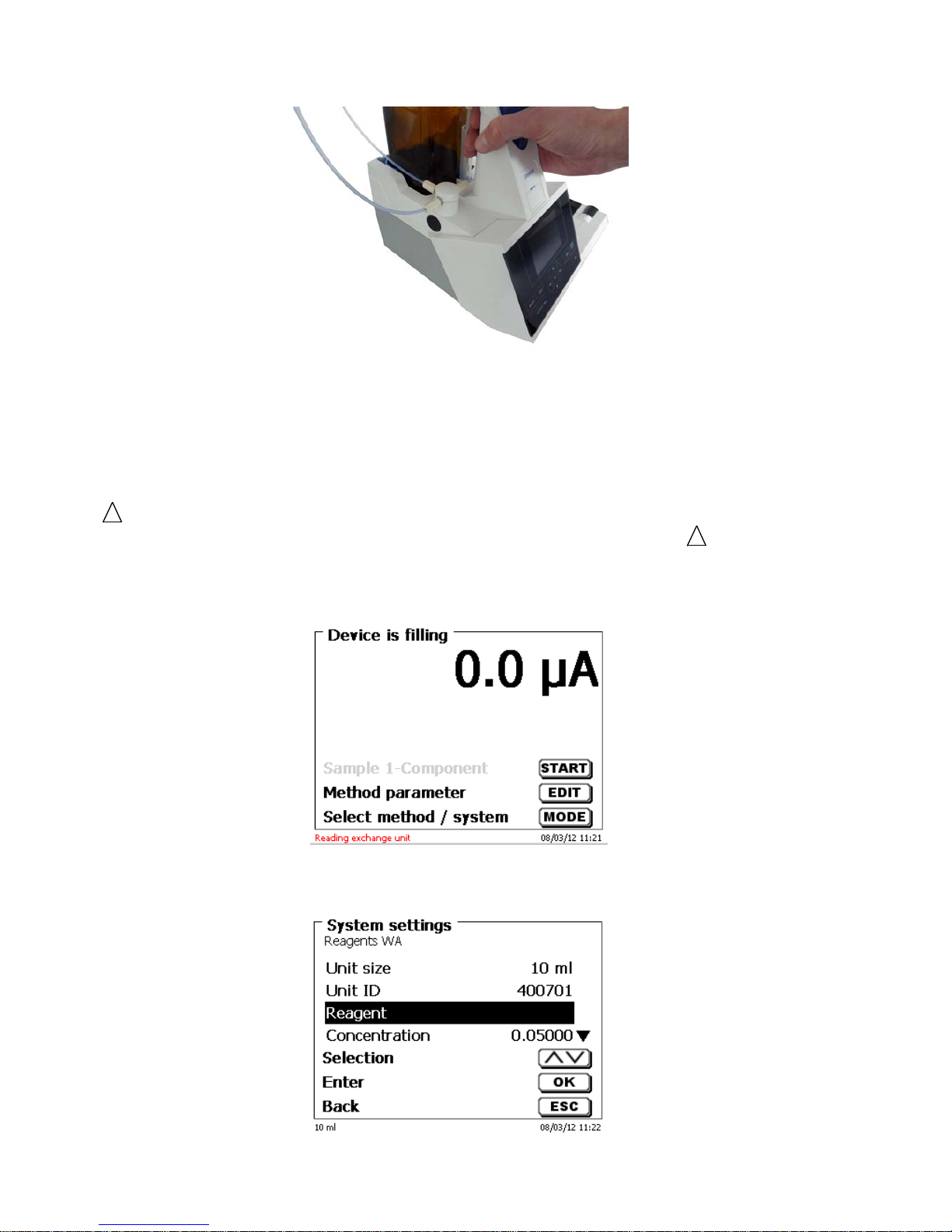
2.6.3 Programming the titration unit
The data from the RFID transponder of the interchangeable uni t will be read immediately (fig. 13).
Fig. 13
Following the reading operation, the input menu for the input of t he r eagents will be shown for approx. 10
seconds (fig. 14). The size of the interchangeable unit is displayed on the left side of the display (here 10 ml).
Fig. 14
Page 20
89
Chapter 2. Unpacking and F ir s t O per ation
When used for the first time, it is recommended to enter here at least the name of the reagent being used. To do
so, confirm the “Reagent “selection with <ENTER>, then ty pe the name and possibly the concentrati on (fig. 12).
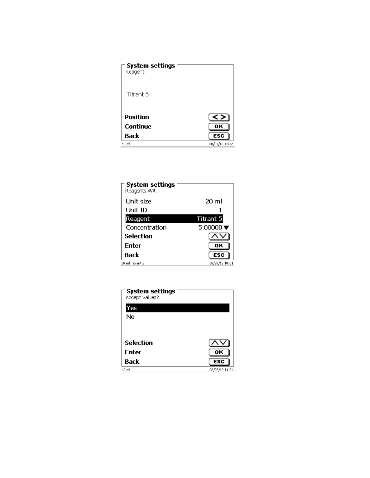
Fig. 15
Press <OK>/<ENTER> to confirm (fig. 15). Following the optional input of additional parameter, press <ESC> to
leave the reagent s menu (fig. 16). The approximate concentrati on of t he KF tit r ant (e.g. 5 or 2) should be entered
under concentration. Thereby the drift in µg/min can be calc ulated in the right dimensions.
Fig. 16
You will be prompted for a confirmation of the values (fig. 17):
Fig. 17
If you selected <Yes>, the values will be written into the interchangeable unit. You can see this from a message
in red colour displayed at the bottom. Upon completion, the lef t bot tom corner of the display will show the new
name of the reagent (fig. 18). In t he pr esent c ase this is Titrant 5.
Page 21
90 Chapter 2. Unpacking and First Operation
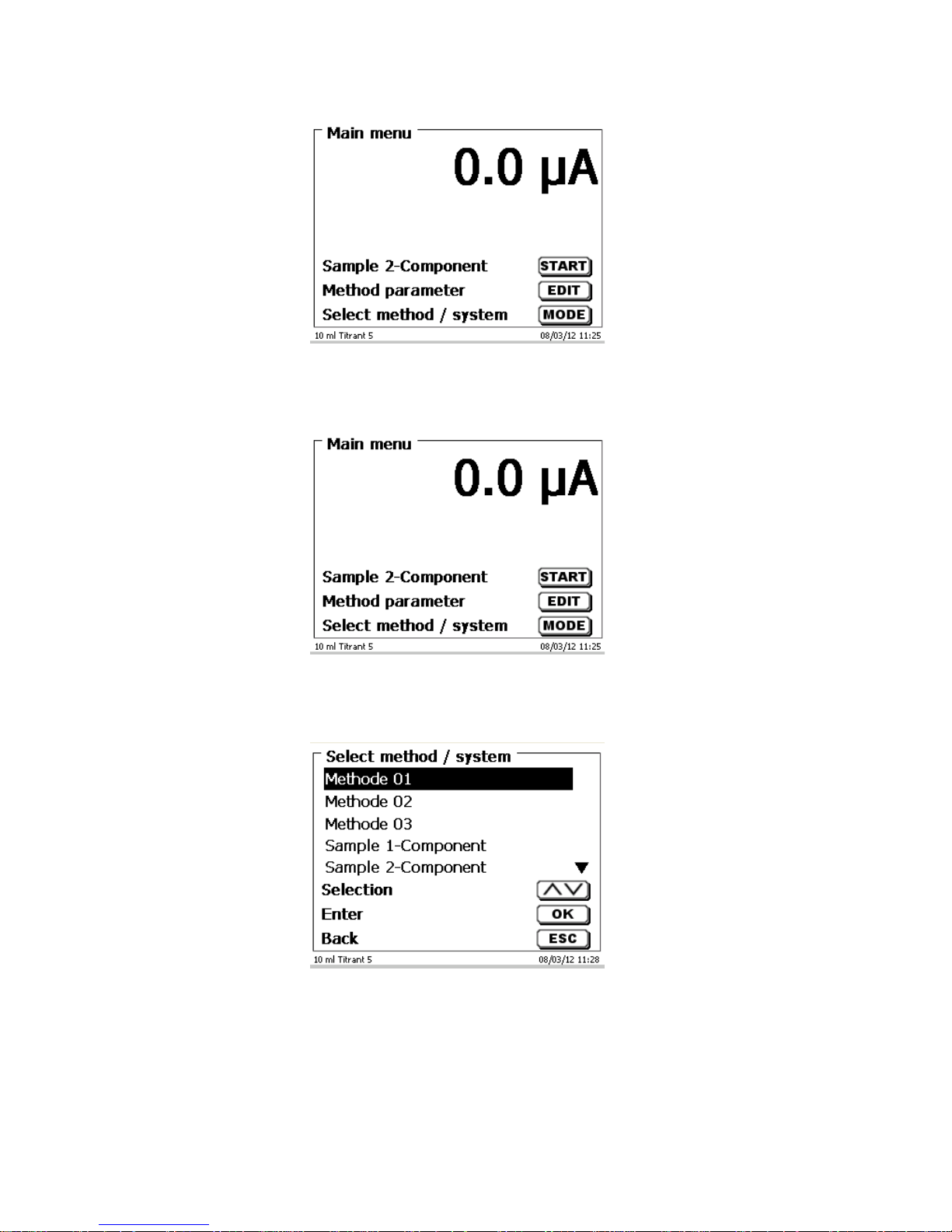
Fig. 18
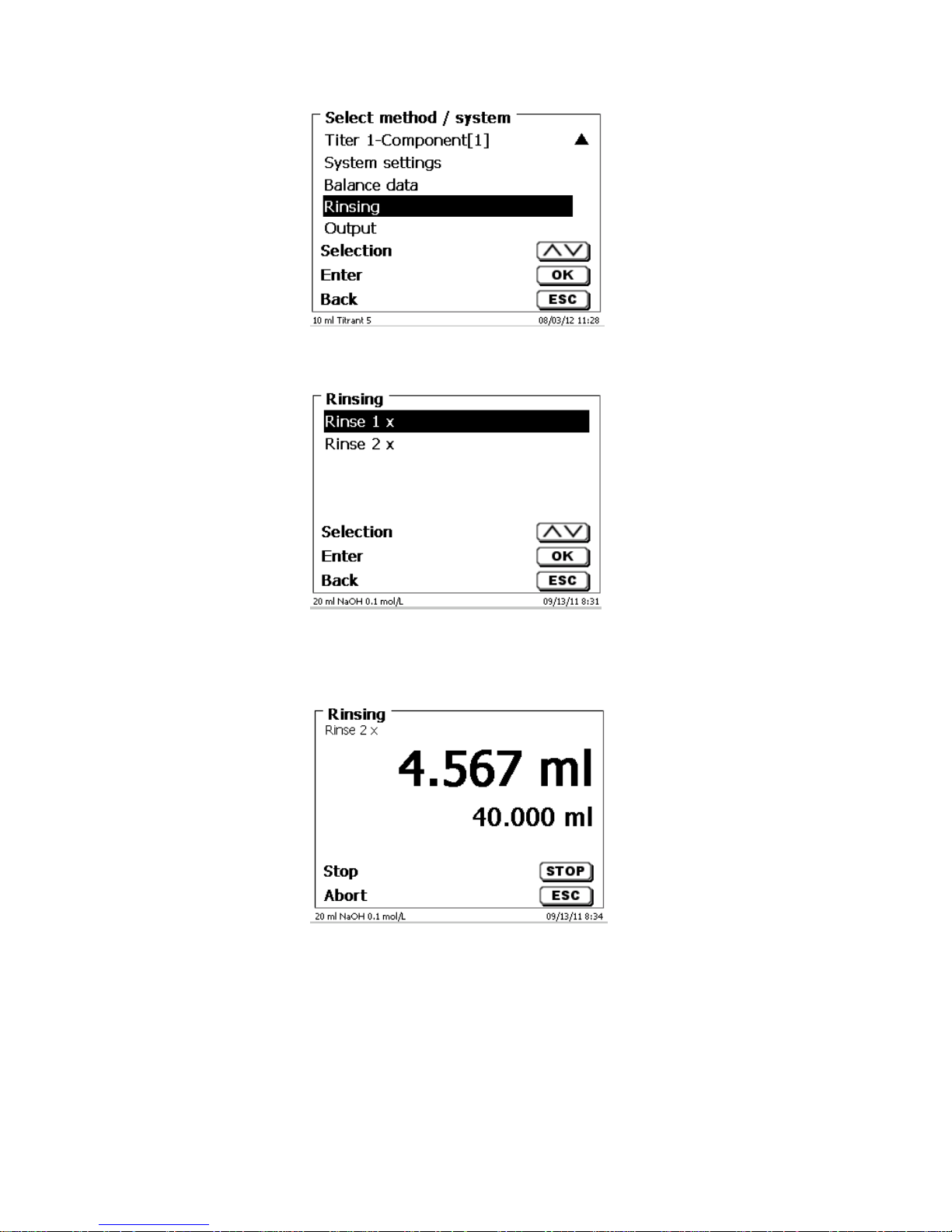
2.7 Initial Filling or Rinsing of the Entire Interchangeable Unit
Initial filli ng of the interchangeable unit is done using the <rinsing > rinsing programme.
Fig. 19
On the main menu (fig. 19), press <MODE> key to navigate t o the methods/system (fig. 20).
Fig. 20
Pressing <↑> twice will take you to the <Rinsing> selection immediately (fig. 21).
Page 22
91
Chapter 2. Unpacking and F ir s t O per ation
Fig. 21
Confirm the selection by pressing <ENTER>:
Fig. 22
At this point you can selec t t he num ber of rinsi ng cycl es (Fig. 19). I ni tial f illing r equir es a m i nimum of two rinsi ng
cycles. You can stop t he rinsing operation (F ig. 20) at any tim e by pressing <STOP> and then resume ri nsing
with <START>.
Fig. 23
While the i nitial filling or ri nsing programme is being run, pl ease place a suffic iently dimensioned waste v essel
under the titration tip. The best is when the titration tip is mount ed in the KF titration vessel.
Page 23
92 Chapter 2. Unpacking and First Operation
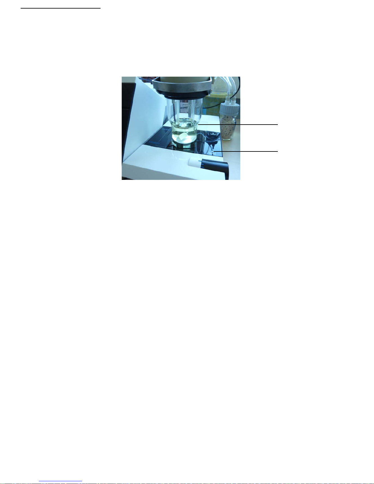
2.8 Filling the titration vessel with solvent
The solvent is pumped from the solvent bottl e into the titration v essel by pushi ng down the front part of the rocker
switch on the titration stand TM 235 KF. Pump solvent into the titration vessel until the titration tip and the
electrode are c om pletely immersed. This will be approx. 35-40 ml of solvent:
Fig. 24
2.9 Replacing the Glass Cylinder and the PTFE Piston
Replacing the glass cylinder and the pi ston does not require any additional tools. In certain cases the piston
extractor has to be used.
• Remove the interchangeable unit from the base unit.
• Unscrew the hose between the glass cylinder and the valv e from the glass cylinder.
• Rotate the blue UV protection 5 to 6 times to the left t o loosen it.
• You can r em ov e the UV protection and pull out of the glass cylinder toget her with the piston inside it.
• Insert a new glass cyl inder and piston (F ig. 25) into the i nterchangeable uni t, and then sli p on the blue
UV protection again.
• Tighten the blue UV protection again by rot ating it 5 to 6 times to the right.
• The pi ston rod shoul d proj ect 1-2 cm out of the interchangeable uni t (Fi g. 26 a). At thi s point , til t t he unit
forward unt il the slant ed bott om side is in fl at c ontact wit h the lab t able (Fig. 26 b). This forc es the piston
into its correc t position. Should the piston be f orced som ewhat t oo far into the glass cylinder, simply pull it
out and place it in the correct position according to the procedure descri bed above.
Filling
35-40 ml
Page 24

93
Chapter 2. Unpacking and F ir s t O per ation
Fig. 24
Fig. 25 a
Piston rod
Piston rod
Glass cylinder
Page 25

94 Chapter 2. Unpacking and First Operation
Fig. 25 b
Basically, it should be noted that within one and the same interchangeable unit only the specified cylinder size
may be installed, sinc e otherwise the coding which is memorised within the interchangeable unit will no longer
match the cylinder si z e. Thi s will entail incorrect dosage. And for the sake of dosi ng and analytical accuracy, it is
also recommended to replace the PTFE pistons each time a defective glass cyl inder is replaced. This applies in
particular to glass breakage, since broken glass may damage the sealing rings of the PTFE piston.
Please note: As a rule, the hoses and cylinders will contain chemic als which may spi ll or be spl ashed around in
the course of disassembly. The relevant safety precaution measures applicable to the handling of the chemicals
concerned have t o be observed.
Page 26

95
Chapter 3 – Working with the titr ator TitroLine® 7500 KF
3 Working w it h th e Titr a tor TitroLin e® 7500 KF
3.1 Front Keyboard
Apart f rom alphanumeric i nput (a-z, A-Z, 0-9) and a few other functions, alm ost all functions can be performed
using the front keyboard.
<Mode>: Methods selection, rinsing, system setti ngs
<EDIT>: Changing the current method, new method, copy and delete method
<ESC>: <ESC> will take you back t o the prev ious menu level.
<START>: Start and Stop of a current method
<FILL>: Filling the unit
The individual functions are described in detail in Chapter 3.4, E xt ernal PC Keyboard.
3.2 Display
The display consists of a gr aphic al LCD display with a resolution of 320 x 240 pix els.
It also offers the possibi lity to display graphics, e.g. t he m easuring curve while or after the titration i s/was running:
Page 27

96
Chapter 3 – Working with the titr ator TitroLine® 7500 KF
3.3 Manual controller “mouse“
The “mouse“ (Fig. 23) can be used dosing applications and sample preparation methods. The mouse is not
included in the scope of delivery of the TL 7500 basic unit.
Fig. 26
Mode
Black key
Grey Key
Dosage through Dosage method
Start dosage
Filling
Preparation of solutions
Start dosage
Filling
3.4 External PC Keyboard
Keys
Function
<ESC>
<ESC> will take the user to the previous level on the
menu.
<F1>/<START>
Start of a selected met hod
<F2>/<STOP>
Stop of the current method
<F3>/<EDIT>
Change of the current method, new method, copy method
<F4>/<FILL>
Fill the interchangeable unit
<F5>/
Display and modific ation of the balance data. With <Shift +
F5> display and modification of t he global m em ori es
<F6>/<MODE>
Selection of met hod, rinsing, system settings
<F7>/<SYS>
System settings (language selection, time/dat e .. .)
<F8/<CAL>
Without function
<F9>/+ / -
Change of sign
<F10>/<DOS>
Call dosing menu
Num/ Scroll
Lock/ Lock
Without function
Prt Sc
Sys Rq
Without function
<ESC>
Selection of the m ethod-selection menu from the main
menu.
Elders: <ESC> will take you back to the prev ious l ev el in
the menu.
< ↑> < ↓ > <←> <→>
Selection of i ndiv idual menus and numeric values
0...9
Input of numeric values
<ENTER>
Confirmati on of input par am eters
< ←Backspace >
Deletion of one input digit / an input character to the left of
the blinking cursor
Letters,
ASCII-symbols
Alphanumeric input possible. Uppercase and lowercase
possible.
All other keys
Do not have any function
Page 28

97
Chapter 3 – Working with the titr ator TitroLine® 7500 KF
3.5 Menu Structure
There are 4 selection menus:
• Start or main menu
• Met hod par ameters
• Met hod sel ec tion
• System settings
After power-up, the main m enu is always the fi rst menu to appear. The method di splayed will always be the last
method that was used (Fi g. 27).
Fig. 27
Pressing <START > will result in the immediate ex ecution of the m ethod shown. <EDIT>/F 3 will take you t o the
method parameters (Fi g. 28).
Fig. 28
At this point you can
• modify the current method
• create a new method
• call and memorise standard methods
• copy or delete an existing method
Use the <↓> und <↑> keys to select the submenus, confirm your selection with <OK>/<ENTER>. <ESC> will take
you back to the main menu.
Page 29

98
Chapter 3 – Working with the titr ator TitroLine® 7500 KF
<MODE>/F6 leads you to the “sel ec t method“ menu (Fig. 29).
Fig. 29
Existing methods can be selected by pressing the <↓> und <↑> keys and confirming the selection with
<OK>/<ENTER>. O nce the selecti on made, you wil l return to t he main menu wit h the newly s elected m ethod. If
no method is selected, < ESC> will also tak e y ou bac k to the main m enu.
To navigate dir ectly to the system settings (Fi g. 30 and Fi g. 31) you can use the <SYS>/F7 key; you can als o
navigate there through the method selection menu.
Fig. 30
Fig. 31
Page 30

99
Chapter 3 – Working with the titr ator TitroLine® 7500 KF
3.6 Main Menu
After power-up, the main m enu is always the fi rst menu to appear. The method di splayed will always be the last
method that was used (Fi g. 32).
Fig. 32
3.6.1 Standard methods of KF Titration
If no titration has been performed yet, it is recommended to load one of the standard methods. These methods
have default par am eters and can generally be used immediately wit hout changes. From the main menu, press
F3/EDIT to access the methods menu:
Fig. 33
From this menu, select the appropriate standard method:
Fig. 34
Page 31

100
Chapter 3 – Working with the titr ator TitroLine® 7500 KF
Standard methods KF Application
Titer 1-Component (li quid standard) Determinati on of t he c onc entration of the titration
agent. Suitable for 1-component reagents. Standard is
a liquid standard in ampoules with a concentration of
10 mg/g.
Titer 1-Component ( soli d standar d) Determinati on of t he c onc entration of the titration
agent. Suitable for 1-component reagents Standard is
the standard substance sodium tartrat dihydrate with a
water amount of 15.66 %.
Titer 1-Component ( water) Determinati on of t he c onc entration of the titration
agent. Suitable for 1-component reagents Standard is
pure water
Titer 2-Component (li quid standard) Determinati on of t he c onc entration of the titration
agent. Suitable for 2-component reagents. Standard is
a liquid standard in ampoules with a concentration of
10 mg/g.
Titer 2-Component ( soli d standar d) Determinati on of t he c onc entration of the titration
agent. Suitable for 2-component reagents Standard is
the standard substance sodium tartrat dihydrate with a
water amount of 15.66 %.
Titer 2-Component ( water) Determinati on of t he c onc entration of the titration
agent. Suitable for 1-component reagents Standard is
pure water
Sample 1-Component Method for sample titr ations with 1-component
reagents
Sample 2-Component Method for sampl e tit r ations with 2-component
reagents
Statistic s are switched on. The mean value of the titer in mg/ml is automatically saved in the attachment. It i s then
used automatically in the sample titration.
The results of the sample titration are calculated in %. If needed, t he unit can be converted into other units of
measure, such as ppm.
3.6.2 Automatic KF Titration
The method being di splayed c an now be carri ed out im m ediately wit h <START>. The precondi ti oning is run f ir st.
The solvent and the titration vessel contai n m oisture (water) that should not influence the calc ulation of the result.
The conditioning is run automatically after the Start button or t he F1 key are pressed. The final conditions are t he
same as the conditions of the actual sample titration.
Page 32

101
Chapter 3 – Working with the titr ator TitroLine® 7500 KF
Fig. 35
When the final criteria are met, then there is an audible signal and Conditioning ready is shown on the display:
Fig. 36
The conditi oning remains activ e until the act ual titr ation is started by pre ssing <F1/START>. You are prom pted
immediately to add t he sample:
Fig. 37
After the sample or the standard is added, you must press <F1/START> again. Dependi ng on the method
settings, you will be pr om pted f or the sam ple identification (Fig. 38) and the weighed-i n quantity (Fig. 39). You
can use an external PC keyboard f or entering a 20-digit alphanumeric sample I D.
Page 33

102
Chapter 3 – Working with the titr ator TitroLine® 7500 KF
Fig. 38
Fig. 39
The balance data can be ent ered usi ng the f r ont key board or an ex ternal keyboar d. T he input i s to be conf i rmed
with <OK>/<ENTER>.
In the case of an automatic acceptance of the balance data, the weighed-in quantities will be read in f rom a
memory. If t he memory does not contain any bal ance data, a message will appear to indicate that no balanc e
data are present:
Fig. 40
Pressing the Pri nt k ey will t ransf er t he balanc e data, t oo. T i tration wil l then begi n di rect ly aft er t he transf er of the
balance data without any further confirmation being necessary. The display shows either
the use in ml with the drift in µg/min
or the drift with the measured value in µA
or the titration curve in ml/time [s].
You can switch between the individual displays with the <F6/MODE> k ey: The graphics are scaled automatically:
Page 34

103
Chapter 3 – Working with the titr ator TitroLine® 7500 KF
Fig. 41
Fig. 42
Fig. 43
Scaling of the c hart will be done aut omatic ally. T he result will be display ed at the end of the tit rati on (Fig. 44 and
45).
Fig. 44
Page 35

104
Chapter 3 – Working with the titr ator TitroLine® 7500 KF
<MODE>/<F6> can be used to view the titration curve or further results:
Fig. 45
If a print er is connected, t he results wil l either be printed accordi ng to the sett ings made f or the met hod, or el se
they will be memori sed in the form of a PDF- and CSV-file file on a connected USB stick. If no printer or USB
stick is connected, the bottom left corner of the display will show the message “no printer“ or “no USB
stick”.<ES C> will t ak e you back to t he mai n menu where you can start the next titration immediately .
3.6.3 Dosage
To start a dosage method, please use the <S TART>/<F1> or the black key of the “mouse“.
Fig. 46
Fig. 47
The dosed volume will be bri efly displayed before the display ret ur ns to the main m enu.
Page 36

105
Chapter 3 – Working with the titr ator TitroLine® 7500 KF
Fig. 48
Fig. 49
The next dosage oper ation can be star ted immediately. Filling of the unit will occur autom atically. This option c an
be switched off. T hen the cylinder will be filled when the m aximum cylinder volume is reached. The unit can be
filled at any time usi ng <FILL>.
A dosing operation can al so be perform ed without any dosing m ethod wit h the <DOS>/<F 10> key of the external
keyboard:
Fig. 50
This is the point to input the volum e whic h will be dose d f ollowing the confirmation wit h <ENTER>/ <OK>:
Page 37

106
Chapter 3 – Working with the titr ator TitroLine® 7500 KF
Fig. 51
Pressing the <ENTE R>/<OK> k ey will c ause the nex t dosing oper ation to be performed immediately:
Fig. 52
In this case further dosages can be perform ed using <ENTE R>/<OK>. Fill ing of t he unit following dosage will not
occur automatic ally here, unless the maxim um cylinder volume has been reached. T he unit can be filled at any
time using <FILL>. <E S C> will t ak e you back to the main menu.
Page 38

107
Chapter 3 – Working with the titr ator TitroLine® 7500 KF
3.6.4 Preparing Solutions
The so-called “P reparing solutions“ m ethod is a special dosi ng method. In this proces s, a solvent is dosed to a
sample weight of a substance until the desired target concentrat ion is reached:
Fig. 53
Fig. 54
Fig. 55
If the calculated volume is greater than the maximum volume, an error message will be displayed and dosage will
be suppressed for saf ety r easons:
Fig. 56
Page 39

108
Chapter 4 Method Param eters
4 Method Parameters
From the main menu (Fig. 53), <EDIT>/<F3> will take you to the method parameters:
Fig. 57
4.1 Method editing and new method
If you select < edit m ethod> or <new method> you will be taken to the modif ication or new creati on of a method.
Selecting < new m ethod> will always lead to the prompt for the input of a met hod name (Fig. 58). This prompt will
not appear in the case of the m odification of an already created method.
Fig. 58
The method name can contain up to 21 characters. Special characters are also possible. If no keyboard is
connected, the m ethod name being displayed has to be adopted (in the present case “Method 04“). Numbering of
methods will occur automatically. P r ess <OK >/< E NTER> to confirm the input. The method name can be changed
at any time. Please continue at this point with Chapter 4.5.
4.2 Default methods
The <Default methods> item of the TitroLine® 7500 KF contains a series of ready-made standar d methods which
can be conveniently selected (Fig. 59).
Fig. 59
Once the selecti on m ade, you ar e dir ectly pr om pted for the input of the method name.
Page 40

109
Chapter 4 Method Param eters
Fig. 60
The standard name may be adopted or modified. Subsequently, you will be taken to the <Change method
parameters> item. Please cont inue at this point with Chapter 4.6
4.3 Copy Methods
Methods can be copied or stored with a new name. If you select this function, the cur r ent method will be copied
and you can include a new name
Fig. 61
A new name with t he suffix [1] i s assigned automatically in order to avoid t he existence of two m ethods having
the same name. Subsequentl y, you will be taken t o the <Change method param eters> item. Then you proceed
with Chapt er 4.6.
4.4 Delete Methods
If this function is select ed, you will be prompt ed to know whether the current m ethod is actually to be del eted.
You have to reply <Yes> in explicit terms and also confirm this reply with <OK>/<ENTER>.
Fig. 62
Page 41

110
Chapter 4 Method Param eters
4.5 Print method
The currently selec ted method can be printed on a connected printer or stored on an US B drive as PDF file
Fig. 63
4.6 Change Method Parameters
The input or modific ation of the method name was already described in Chapt ers 4.1 and 4.3.
Fig. 64
4.6.1 Method type
On the <Method ty pe> you can select whether you wi sh to perform a manual or aut omatic tit ration, a dosage or
whether you wish to prepare a solut ion.
Fig. 65
The selection of the Method type will have an influence on the further parameterisation of the method. For
instance, if you select the dosi ng mode, neither a sel ection of a formula nor a change of the autom atic titration
mode (KF and dead stop) will be available.
Page 42

111
Chapter 4 Method Param eters
For an automatic titration, you can select from the following modes:
• KF titration
• Dead St op titration
4.6.1.1 KF and Dead stop titration
KF titrati on is a specif i c form of dead-stop t itr ation. In norm al dead-stop ti tr ation, titr ation i s to the specif i ed value
in µA, which must be maintai ned for a defined time. In KF titration, this still occurs, but a specified drift criterion in
µg/min must also be met. With KF tit ration, a conditi oning step i s also is preset in or der to eliminate any moisture
in the titrati on v essel and t he solvent.
The first stage of t he Dead stop and K F t it ration c onsists in t he conti nuous do sing up t o a del t a v alue away f rom
the set end point . The do sing speed can b e adju sted. Subsequentl y, ti tration i s performed wit h linear step sizes
between the delt a val ue and the end point.
The following titr ation parameters can be set for the dead-stop and KF titr ation:
Titration paramet er Dead-stop titration KF t itrat ion
µA-Endpoint X X
Delta µA-value X X
Linear steps in ml X X
Endpoint del ay in s X X
Delay time (between linear steps) X X
Start delay time / extraction time X X
Conditioning on/off - X
Pre - titration in ml X X
Polarization voltage in mV X X
Minimum und maximum titration time in s -
Max. titration volume X X
Drift in µg/min X X
Dosing speed in %
4.6.2 Result
Result offers the following sett ings:
Fig. 71 d
The Result text may cont ain up to 21 alphanumeric characters including special characters.
Page 43

112
Chapter 4 Method Param eters
Fig. 72
Please confirm your input with <OK</<ENTER>.
4.6.2.1 Calculation Formula
The appropriat e c alc ulation formula is selected on the Formula selectio n submenu:
Fig. 73 a
The following calculation formulae are available for automatic titration mode:
Formula
Additional information
EP
Formula for calculating only the ml
consumption
(EP-B)*T*M*F1/(W*F2)
Formula for calculating the
concentration of a sample taking into
account a blank value in terms of ml.
(W*F2)/(EP-B)*M*F1)
Formula for calc ulating a titer (T) of a
titration solution.
The abbreviati ons used here have the following meaning:
EP: Consumption at the end point in ml
B: Blank value in ml. Mostly determined by way of tit r ation
T: Titer of the titration solution (e.g. 5.012)
M: Mol; mol- or equiv alenc e weight of the sample
F1-F5 Factor 1-5. conversion factors
W “Weight“, weighed-in quantity in g or volume in ml.”
Page 44

113
Chapter 4 Method Param eters
After selecting a formula, please confirm your selection with <OK>/<E NTER>:
Fig. 69
The values for the blank value and the factors can be entered manually or read from a global m emory. The
values from a global memory were defi ned in advance by a titration or were manually entered.
Fig. 70
Fig. 71
The used global memory is displ ay ed. Here in the example it is MO1 and MO2:
Fig. 72
Page 45

114
Chapter 4 Method Param eters
Storing results i n global memories is described in Chapter 4.6.3.7
The values of the individual parameters of the sel ected cal c ulation formula can now be input one by one.
Fig. 73
4.6.2.2 Sample weight and volume (sample quantity)
Fig. 74
Fig. 75
The Sample Quantity (W) item is used to select whether one is wishing to use a sample weight or a sample
volume for titrati on or sol ution preparation.
You have the following options:
• Manual sample weight: The sample weight is enqui red by a prompt at the start of the method/after
conditioni ng ( KF)
• Automat ic sample weight: The sample weight is automatically transferr ed by a connected balance.
• Fixed sample weight: A fixed sample weight i s i nput in g. This weight will then aut om atically be used for
each start of the method.
• Man ual sample volume: The sample v olume in ml is prompted at the start of the method and manual ly
input.
• Fixed sample volume: A fixed sample volume is input in ml. This v olum e will then automatically be used
for each test of the method.
Page 46

115
Chapter 4 Method Param eters
4.6.2.3 Formula unit
The formula unit can be select ed in the Unit submenu.
Fig. 76
Once the selecti on m ade (e.g. %), t he unit will also be displayed as piece of information on the display.
Fig. 77
Page 47

116
Chapter 4 Method Param eters
4.6.2.4 Formulae for the Preparation of Solutions
A selection of special calculation formulae is available for the Prepare Solutions mode. The appropriate
calculation formula is selected on the Formula Selecti on submenu:
Fig. 78
A selection of 3 differ ent calculation formulae is available:
W*(100-Fa-Fb)*Fc/Fd - W*(100-Fb) / (100*Fe) +Ff
W*(100-Fa-Fb)*(Fd/Fg ) - W*(100-Fb) / (100*Fg) +Ff
W*(100-Fa-Fb)*Fc / (10 0 * Fd)
Meaning of the individual factors:
W: Weight of the sam ple in g
Fa: Soluble foreign-matters portion in %
Fb: insoluble foreign-matter porti on in %
Fc: Conversion factor for it unit
g/l = 10
mg/l und ppm = 10000
g/100 ml = 1
% = 1
Fd: Target concentration of the solution to be prepared in g/l, m g/l (ppm ) , g/ 100 ml , or %
Fe: Specific weight of the weighed-in sample in g/cm³
Ff: Volum e c or r ection in ml. this volume correction is the required surpl us dosage for compensating the
volume contracti on and the specific-weight difference between the sample weight and the solvent (pl ease
observe the note on volum e c orrection)
Fg: Specific weight of the solvent used in g/cm³
Note on volume correction:
The user has to decide on a case-by-case basis whether a v olume correction is necessary and according to
which procedure thi s corr ec tion is to be performed. As a rule, this volume correction may be omitted in the case
of solutions with v er y l ow percent ages of diluted substance.
Page 48

117
Chapter 4 Method Param eters
4.6.2.5 Decimal digits
To conclude, it is possible to determine the number of decimal digits from 2-6. The standard setting is 2.
Fig. 79
4.6.2.6 Statistics
The mean value and relative standard deviation can be automatically calculated and documented by using
statistics.
Fig. 80
The calculati on of the mean value i s already possible fr om two individual values. The calculati on of the relativ e
standard deviation is only possible from 3 single values. The maximum quantity is 10.
Fig. 81
The mean value and the relative standard deviation (RSD) are shown directl y on the display .
Page 49

118
Chapter 4 Method Param eters
4.6.2.7 Global Memories
Results of titrations can be writt en into one of the 50 global memories (M01 - M50) for additional calculations.
Fig. 82
The mean v alue is writt en i nto t he global mem ory when t he stat i stic is switc hed on. You ent er the subm enu wit h
<Enter/OK>. If a global memory has not been created, a memory can be created by using the insert key <Ins>.
The titrat or proposes a memory name, such as M01 (M01- M50). The name of the memory can be changed i n
reference to the application. Here in this example of “M01” for “Blank value”.
Fig. 83
This simplifies later the allocation of the global memor y in another m ethod.
Example Titer d etermination: The titer in mg/ml is defi ned with an extra Ti ter met hod. The result in mg/ml is
thereby automati c ally written into global memory “Exchangeable unit”.
Fig. 84
The menu for the global memory can always be accessed by pressing Shift+F5 or vi a system settings. The name
or values can be changed by using EDIT /F 3 and have the methods shown that are used in the global mem ori es.
Page 50

119
Chapter 4 Method Param eters
Fig. 85
4.6.3 Titration parameters
The <Titration parameter> submenu is used to determine the actual parameters of the method. T he par am eters
were already introduced in chapter 4.6.2.1:
Fig. 86
Fig. 87
Generally applicable titration parameters
Depending on the t itration mode (KF or dead stop titrati on) it is possible to ent er a variety of parameters. The
following parameters are valid for the KF and dead stop titr ation modes:
• Initial waiting time
• Fixed delay
• St ep si z e
• Pretitration
• Polarization voltage
• End of tit r ation
Page 51

120
Chapter 4 Method Param eters
Start delay time/ E xt ract io n time (KF):
With dead-stop ti tration, the start wait time passes at the begi nning of titrati on. In KF titration, t he star t wait time =
the extracti on time. The extracti on time ends after the sample is supplied. The start wait/ extraction time can be
specified bet ween 0 and 999 seconds.
Fig. 88
Conditioning
Conditioning ( only KF) is activated for every KF method. It can be shut off via a PC for exter nal c ontrol:
Fig. 89
Fixed delay time
The fixed delay ti me i s the waiting time between the li near titration steps at the end of the titration until the
Endpoint. The fixed delay time can be set between 0 and 999 seconds:
Fig. 90
Step size
The step size can be set from 0.001 to 5. 000 ml . typical value for the KF titration are 0.002 – 0.01 ml.
Page 52

121
Chapter 4 Method Param eters
Fig. 91
In this type of titr ation, linear step width is used after the continuous titration stage.
Titration direction (only dead stop titration mode)
The titrati on direction can be set to “increase“ or “decrease“. For instance, i f you wish to perf orm a sulfurous
titration with iodine solution you have to select “increase“. For an iodometric back titrating with Sodium
thiosulfate you have to select “decrease“.
Fig. 92
Pretitration
If the titration agent consumption is roughly known, you can set a pretitration volume on the <Pretitration>
menu. In this process, a defined volume is dosed ( = pretitrated) following the initial waiting time. After the
addition of the preti tration v olume, another def i ned span of t ime is observ ed as the waiti ng time bef ore the nex t
titration step is added. The pretitration volume is autom atically added to the titration agent consumption. The
pretitration v olum e can be set from 0.000 and 99. 999 ml , the possible range for setti ng the waiti ng tim e following
pretitration is between 0 and 999 seconds.
Fig. 93
Polarization voltage
Polarisation voltage in mV can be set for KF and dead stop titration.
Page 53

122
Chapter 4 Method Param eters
Fig. 94
The values can be set between 40 and 220 m. The pr e-setti ng is 100 mV.
Low polarisation voltage: insensitive
High polarisation voltage: sensitive
4.6.4 Titration end
The end of a titration is reached, and the result will be calculated as soon as, or if, respectively:
• The def ined End value i n µA value has been reached
• The E ndpoint delay in seconds has been adhered
• The dr ift value in µg/min has been reached
• The pr edefined value ml has been reached (Maximum t itr a t io n v olume)
• The conditions for minimum and maximum titration time are maintained
Fig. 95
Fig. 96
Maximum titration time
The maximum t itration time c an be set between 0 – 9999 seco nds. The defaul t setting is 600 seconds. The
maximum titration time is generally used for KF titration, which can create a high continuous drift from a
secondary reaction and thus cannot reach a stable endpoint.
Page 54

123
Chapter 4 Method Param eters
Minimum titration time
The minimum titration time can be set between 0 – 9999 seconds. The default setting is 10 seconds. The
minimum tit rati on time prevent s prem ature t erminati on of the t itrati on if t here i s a delay in t he ex tracti on of water
from the sampl e. The minim um titration t ime is used in com binati on with the ext raction tim e. It ex pires while the
extraction time is still active.
Maximum titration volu me
Setting of the maximum titration volume should always make sense. It also serves as a safety criteria to
prevent exc essive titration, i.e. a possible overflow of the ti tration vessel. T he maximum titration v olume can be
set between 1.000 und 999.999 ml:
Fig. 97
The default setting is 50 ml. The volume for conditioning is included in the count!
Drift
The drift i s calculat ed in µg/mi n fr om the titr ation mean c onsumpt ion/t im e x concentrati on of t he tit rati on solution.
A stable drift at the beginni ng and end of the titration is im port ant if y ou want to o btai n reproduc ibl e result s. Thi s
applies in part icular to sam ples with low water content in the bott om percentage range (<0, 1%). The drif t value
should also not be set too low because the ti tration time will increase considerably. An airtight and dry titration
vessel has a drif t of < 50 µg/mi n. This corresponds to consum pti on of 10 µl ( 0,01 ml) of ti trant at a concent rati on
of 5 mg/ml. For many applicati ons, a drift value of 100 – 150 µg/mi n is entirely sufficient. T he default drift value
setting is 100 or 150 µg/min for sample titration. 50 µg/min is the def ault setting for titer methods.
Endpoint µA
The range of t he µA input c an be selected bet ween 0.0 and 100. 0. For K F titr ation, values between 10 – 30 µA
are practical. The standard value is 20 µA.
Delta Endpoint µA
The Delta value in µA is one of the most impor tant parameters for KF and dead-stop t itration. T he lower the Delta
value is, t he longer the ti tration (dosing) i s at a conti nuous speed. W hen using single-component reagents an d
pure methanol as a solvent, the Delta value shoul d be set at < 5 µA. Values of 2 or 3 µA are pract ical. This i s
because the KF reaction in methanol runs relatively slowly. When using double-component reagents or also
when using combinati on solv ent s, the Delt a value must be set at > 10 t o prevent r apid ov ertitrati on. V alues of 14
or 15 µA are practical.
Endpoin t de la y
The endpoi nt del ay is set in second s. It can be set fr om 0 – 100000 second s. The standard value is 10 seconds.
Brief endpoint delay s (5 seconds) are practical when
• using very small increments (e.g., 0,001 ml)
• using a titer of 1 mg/ml
• creating a secondary r eac tion with a higher drift value
Page 55

124
Chapter 4 Method Param eters
4.6.5 Dosing parameter
Fig. 98
The dosing param eters (dosing speed, f illing speed and m ax. dosing/titrati on volume) are determined f or each
method. This applies to all types of methods such as automatic titration, dosing and Solution Prepar ation.
Fig. 99
The dosing speed can be set in % fr om 1 to 100 %. 100 % is the maximum dosi ng speed.
Interchangeabl e un it
Max. dosing speed [ml/min]
WA 05
10
WA 1 0
20
WA 2 0
40
WA 5 0
100
The filling speed can be set in t er ms of seconds f r om 20 to 999. The standard setti ng of this val ue is 30 seconds.
For dil uted aqueous solutions the f illing speed can be six to 20 second s. For non-aqueous solut ions the filling
speed should be set to the 30 seconds. In t he case of highly viscous solutions such as concentrated sulphur ic
acid the filling speed should be further reduced down to 40 - 60 seconds.
Depending on the met hod type, the (maxim um) living volume or tit ration volume can be set to 999. 999 or even
9999.999.
The following fill ing options can be set for the dosing mode:
Page 56

125
Chapter 4 Method Param eters
Fig. 100
If”off“is selected for filling, filling it will not occ ur autom atically after each dosing step.
If “intelli gent before“ is select ed for filli ng, a verificati on will be performed each time pri or to the next dosing st ep
in order to det ermine whether the dosing step can still be made wit hout a filling operation. Should this prove to be
impossible, the first thing to occur is filling, followed by the dosing step.
If “intelligent after“ is selected for filling, a verification will be performed after the next dosing step to find out
whether the next dosi ng step c an still be made without filling.
If „always“ is selected for filling, filling will occ ur autom atically after each dosing step.
4.6.6 Sample identification
In the manual titration and in the preparation of solutions it is possible to input a sample identification. The
possible input includes manual, automatic or no sample descript ion at all.
Fig. 101
For a sample description of t he ’manual’, a prompt for the sample description will always be displayed at the start
of the method (Cp. also chapter 3. 6, Main m enu). For an ‘autom atic’ sampl e descripti on there will be selected a
master descripti on (in the current case this is water, cp. Fig. 102), which will then aut omatically be num bered
starting on 01.
Fig. 102
After a new power-up, numbering will resume with 01.
Page 57

126
Chapter 4 Method Param eters
4.6.7 Documentation
Fig. 103
Three different format settings are av ailable for documentation on a printer or USB device: “short”, “standard
(with curve)” and “GLP ”:
Fig. 104
Method type
Short documentation
Standard
documentation
GLP-Documentation
Automatic titration
Method name, date, time, duration
of titrati on, sam ple description,
weight/volum e, starting and end
measurement values, results and
calculation formula
Same as ‘Short
documentation’ + titration
curve
Same as ‘Standard
documentation’ +
method contents
Dosing
Method name, date, time
N/A
Same as ‘Short
documentation’ +
method contents
Prepare soluti ons
Method name, date, tim e, sam ple
designation, weight/sample,
results and calculation formula
N/A
Same as ‘Short
documentation’ +
method contents
Page 58

127
Chapter 5 - System Settings
5 System settings
Fig. 105
From the main menu (Fig. 107), <SYS>/<F7> will get you to the system setti ngs:
Fig. 106
Setting the nati onal language was already described in Chapter 2.5.
5.1 Interchangeable Unit - Reagents
Each interchangeabl e unit is equipped with an RFID transponder. T his transponder can be used to store the
following inf ormation:
• Uni t size: (the default setting, c annot be changed)
• Uni t ID: (default setting, cannot be changed)
• Reagent name: (default: blank)
• Concentration: (default: 1.000000)
• Concent r ation determined on: (Date)
• To be used until: (Date)
• Opened/ P r oduc ed on: (Date)
• Test ac c or ding to ISO 8655: (Date)
• Charge description: (def ault: no c har ge)
• Last modification: (Date)
Page 59

128
Chapter 5 - System Settings
Fig. 107
Fig. 108
Fig. 109
If you leave the <Reagents WA> menu using <E S C>, you wil l always be prompted to know whether you wish to
adopt the values:
Fig. 110
If <Yes> is selected, the updat ed v alues will be written into the RFID transponder of the interchangeable unit.
Page 60

129
Chapter 5 - System Settings
5.2 RS232 Settings
The <RS232 setti ngs> item can be used to deter mi ne the device address of the TitroLine® 7500 KF and set the
parameters of the t wo RS232 i nterfaces independent from each other:
Fig. 111
The device address can be set from 0 – 15. Addr ess 1 is the def ault setting:
Fig. 112
The baud rate is preset to 4800. It m ay be set to 1200 – 19200:
Fig. 113
Page 61

130
Chapter 5 - System Settings
Fig. 114
The parity can be selected am ongst <No>, <Even> and <Odd>. <No> is the default setting.
Fig. 115
You may select between 7 and 8 data bits. 8 bits is the default setting.
Fig. 116
The RS232 parameter s can be set t o the factor y settings.
Page 62

131
Chapter 5 - System Settings
5.3 Date and Time
The factory tim e setting is Central European Time. This setti ng m ay be changed, where necessary:
Fig. 117
5.4 Password
The activation of t he password has not yet been implemented for the current ver si on 12_18. Please contact SI
Analytics for sending you an update version.
5.5 RESET
RESET will reset all settings to the factory setting.
Please note: All methods wil l also be del eted. So pl ease print the m et hods or export /c opy them to a connected
USB storage medium (this will be possible with a higher update!).
The RESET has to be confirm ed separatel y onc e again:
Fig. 118
Page 63

132
Chapter 5 - System Settings
5.6 Printer
For connecting printers please refer to chapter 7.3.
Fig. 1 19
5.7 Device Information
<Device Informati on> contains information about
• the c ur r ent software version
• the serial number of the device
• printer driver and update version
• device address
• number of measurements (Starts of a method)
• a number of strokes/filling cycl es
Fig. 120
5.8 System Tone
This is the poi nt t o set the volume of the system sounds and the fr ont keyboard of the device. The system sound s
become audible e.g. at the end of the titration or in case of an erroneous operation. The keys of the front
keyboard produce a cli c ki ng sound if the key was used successfully.
Page 64

133
Chapter 5 - System Settings
Fig. 121
No sounds will occur when the external keyboard is used.
5.9 Software Update
Fig. 122
An update of t he dev ic e software requi re s a USB sti ck c ontai ni ng a new v er sion. F or t his operati on, t he two fi l es
that are needed hav e to be located in the root directory of the USB device:
Plug the USB device into a free USB-A port, wait for some seconds, and then select the Software Update
function. The v alid software update s will be shown on t he display. In the present case thi s is Version “16_11 “ of
19 April 2011.
Page 65

134
Chapter 5 - System Settings
Fig. 123
After starti ng the updat e usi ng <O K/E NTER>, next thing to appear is the following gr aphic:
Fig. 124
which will change aft er a few seconds to the f ollowing display:
Fig. 125
Upon completion of the update (approx. 2-3 minutes), the device will shut down the software completely and
proceed to a new start.
Important: In the course of an update, the methods will not be deleted! You can conti nue to use them.
If no valid update file is stored on t he US B sti c k, the f ollowing message will appear:
Fig. 126
Page 66

135
Chapter 6 Data Communication via RS232 and USB-B interface
6 Data Communication via RS232- and USB-B interface
6.1 General Inf ormation
The burette TitroLine® 7500 KF has two serial RS232-C interf aces to communicat e data with other devices. By
means of these two interfaces it is possible to operate sever al dev ic es on one computer (PC) interface.
In addition to that, the TitroLine® 7500 KF also has an alternatively USB-B interface, which can only be used to
connect a PC.
RS232-C-1 establishes the conn ecti on to a connected com puter or to the previous dev ice of the “Daisy Chain“.
At the RS232-C-2 it is possible to connect additi onal devices (Daisy Chain Concept).
PIN assignment of t he RS232-C i nterfaces:
6.2 Chaining multiple devices —“Daisy Chain Concept“
In order to act ivate sev eral devices in a chai n indivi dually, each dev ice must have an own dev ice address. For
this it is at first necessary to establish a connecti on from the computer to the RS232-C i nterface 1 of the first
devise in the chain by means of a RS232-C data cable, e.g. Type No. TZ 3097. With the additional RS232-C data
cable, Ty pe No. T Z 3094, the RS232-C- interface 2 of the fir st devi ce i s connected with t he RS232-C-int erf ace 1
of the second device. At int erface 2 of the second device it is possible to connect an additional device.
The TitroLine
®
7500 KF can also be connect ed vi a USB cable TZ 3840 (type A (M) – type B (M), 1.8m). It is also
possible to connect t he TitroLine
®
7500 KF via USB cable TZ 3840 (type A (M) --- USB type B (M), 1.8 m) to a
USB interface of a PC. To accomplish thi s connection, a driv er has to be install ed on the PC. Then the USB-B
interfac e takes ov er the function of the RS232-1 interface.
The address alway s consists of two characters: e. g. address 1 of the two AS CII- characters < 0> and <1>. The
addresses can be set f rom 00 to 15, i.e. 16 possibili ties. It must be ensured that the dev ices in a chain have
different addresses. If a device is addressed with its address, this device will process this command without
sending it to another device. The reply to the computer has also an own address. T he addr esses are allocated as
described in Chapter 5.3.
The burette TitroLine
®
7500 KF receives commands f rom a PC at the int erface 1 (USB- B) if t he c omputer knows
the address. It al so sends the an swer v i a this int erface. If the address of the i ncoming c ommand does not m atch
the device address, the complete command will be forwarded to interface 2. Interface 2 is connected to
interface 1 of another device. T his device check s the addre ss as well and r eacts to the command as the first
TitroLine
®
7500 KF did before.
All information (data strings) which arriv e at i nterface 2 of the burette TitroLine
®
7500 KF will immediately be send
to the computer v ia interface 1 (or USB-B interface). Thus, the computer receives the data of all devices. In
practice it is possible to connect up to 16 devices to one computer- (PC-) interface.
6.3 Instruction Set for RS-Communication
The commands consist of t hr ee par ts: Address two-digit aa, e.g.: 01
Command e.g.: DA
Variable, if necessary e.g.: 14
and end of command <CR> <LF>
Every comm and must be completed with the A SCII - sign <CR> and <LF> (Carri age Return and Line Feed).
Only if the respective action has ended the answers will be returned to the com puter.
Example: The command to dose 12.5 ml shall be sent to the burette TitroLine® 7500 KF with the address 2.
The command consists of t he c har acter s: 02DA 12.5<CR LF>
In detail: 02 = Device address
DA = Dosage command with filling and zero points of the display
12.5 = Volume in ml to be dosed
<CR LF> = Control character as command end
PIN-No.
Meaning / Description
1
T x D Data output
2
R x D Data input
3
Digital mass
Page 67

136
Chapter 6 Data Communication via RS232 and USB-B interface
Command Description Reply
aaAA automatic allocation of device address aaY
aaMC1...XX choosing a method aaY
aaBF “filling buret te“. Aufsatz wird gefüllt. aaY
aaBV output of dosed volume in ml aa0.200
aaDA dose volume without filling, with adding the volume aaY
aaDB dose volume without filling, reset of the volume aaY
aaDO dose volume with filling, without adding the volum e aaY
aaGDM dosing speed in ml/mi n aaY
aaGF filling time in seconds (min is 20, default 30) aaY
aaES “ESC“ f unction one step backwards aaY
aaEX “exit“ function.back to main menu aay
aafd µa “dead stop“ measurem ent f unc tion aay
aagdm dosing speed in ml/mi n ( 0.01 – 100 ml/min) aaY
aaGF filling time in sec (adj ustable 20 – 999 seconds) aaY
aaGS out put serial no. Of device aaGS08154711
aaLD output of the measurement data aaY
aaLR output report (short repor t) aaY
aaM output the measurement value µA aaM0.1000
aaLI output method content
aaLO output doc um entation (as configured)
aaRH request of identification aaIdent:TL7500KF
aaRC send last c om mand aa“last command“
aaRS report status aaStatus:“text
possible answers are:
”STATUS:READY“ for ready
”STATUS:dosing“ dosi ng
”STATUS:filling“ filling
”ERROR:busy“ if no interchangeable unit has been attached
aaSM start selected method aaY
aaSEEPROM EEPROM reset t o factory defaults aaY
aaSR stop the actual function aaY
aaSS tit r ation start with the transfer of the pH end val ue aaY
aaSYS5 adjust language to “German“ aaY
aaSYS1 adjust language to “Engli sh“ aaY
aaSYS2 adjust language to “French” aaY
aaSYS3 adjust language to “Spani sh” aaY
aaVE Version number of the software aaVersion
Page 68

137
Chapter 7 – Connection of Analy tical Balances and Printers
7 Connection of Ana l yti c al Bal a nc e s a nd Pr i nt er s
7.1 Connection of Analytical Balances
As it often happens that the sample is weighed in on an analytical balance, it makes sense to connect this
balance to the T itroLi ne
®
7500 KF. To connect the balance t o the TitroLine® 7500 KF , the balanc e must hav e a
RS232-C-interface and t he connecti on cabl e must be confi gured acc ordi ngly. For t he following t ypes of balances
there are already assembled connection cables:
7.1.1 Balance TZ-Number
Sartorius (all t y pes), par tially Kern, TZ 3092
Mettler AT, PR, PM TZ 3093
Mettler, AB-S, AG, PG TZ 3099
Precisa XT-Series TZ 3183
Kern with 9-pole RS232 TZ 3180
For all other t ypes of bal ances it is possibl e to obtai n an already assembl ed connecti on cable (on demand). For
this we need detailed information about the RS232-C-interface of the balance used.
The connection cabl e is to be connected to the RS232-C-interface 2 of the TitroLine
®
7500 KF. This side of the
connection cabl es always consists of a 4-pole m ini-plug. The other si de of the cable can, dependi ng on the type
of balanc e, be a 25-pol e plug ( Sart ori us), a 9-pole pl ug (M ett ler AB-S) or a 15-pol e spec iali sed plug (M ett ler AT)
etc.
In order to allow the balance data to be sent to the TitroLine
®
TitroLine® 7500 KF, the data transmission
parameters of the titrator and the bal anc e m ust c or r espond to eac h other. Additionally, it is necessary to carry out
some more standard settings on the side of the balances:
The balance is to send the balance data via RS232-C only by means of a print command.
The balance is to send the balance data only after the display standsti ll.
The balance should never be set to ‘automatic sending’ and/or ‘send cont inuously’.
‘Handshake’ on the balanc e m ust be set to ‘off’, or even ‘Software Handshake’ or ‘Paus e’.
No special charac ters such as S or St are allowed to be used as prefix in the balance data of the balance
data string. In such a case it might be possible that the TitroLine® 7500 KF cannot pr oc ess the balance data
correctly.
After you have c onnec ted the balance with t he appr opr iate cable to the Titr oLine® 7500 KF and have adjusted all
settings in the balance software, and po s si bly in the TitroLine
®
7500 KF, you can now te st the data transfer of the
balance v ery easily. Start the method. Af ter conditioning, press Enter to start the sam ple titration. Confirm the
sample ID. Then, the display asks you:
a) To press the pri nt -button at the balance Parameters to ‘weighted sample automatically’
b) To enter the weight ed sample then the parameters are still set to ‘weighted sample manually’
Put an object onto the bal ance and press the print button. Aft er the standstill of the balance display t here will be
beep at the TitroLine® 7500 KF and the transmitted balance data appear:
a) Aft er appr ox . 5 sec. in the display and the display changes automat ic ally into the measuring display.
b) The weighted sample must again be confirmed with <Enter> or <OK>.
Page 69

138
Chapter 7 – Connection of Analy tical Balances and Printers
7.2 Balance data editor
Pressing the die <F5/balance symbol > f unction k ey will invoke the so-called balance dat a editor.
A list with the existi ng balanc e data will appear:
Fig. 127
The balance data c an be edited one by one. Following a c hange, a cross wil l appear opposite t he weighed-in
quantity:
Fig. 128
Weights may be delet ed or added i ndiv idually. It is also possible to delet e all weights at one stroke.
Fig. 129
If no balance data is av ailable, the “No balance data found” message will appear:
Page 70

139
Chapter 7 – Connection of Analy tical Balances and Printers
Fig. 130
7.3 Connection of P r inters
The results, calibration data and methods can be printed on the following media:
• HP PCL c om patible printer (A4) chromatic and monochrome (e.g. laser printer)
• Seiko DPU S445 (Thermo paper 112 mm width)
• On the USB stick in PDF- and CSV-format
To connect the printer s to the burette please use the USB socket. When printing, pl ease check whether the
correct print er is connected. It is not possible to print „HP“printer layouts on another thermal printer or vice versa.
The printer settings should always be checked and adjusted af ter changing the printer.
Fig. 131
Only one printer should be c onnec ted for one Titrator because an automatic pri nter recognition is not activated.
Print PDF is the default setting. If you select “Print PDF“, please mak e sure t hat a USB sti c k i s connected to the
device.
Page 71

140
Chapter 8 – Maintenance and Care of the T itroLine® 7500 KF
8 Maintenance and Care of the TitroLine® 7500 KF
The preserv ation of the proper f unctioning of the piston burette requi res testing and m aintenance work to b e
performed on a regul ar basis.
Regular inspecti ons are essenti al pr erequi sites for the correct ness of t he v olume and the proper functi oning of
the piston burette.
The accuracy of the volume is determined by all chemicals-carrying components (piston, cylinder, valve,
titration ti p and hoses). These parts are subject to wear and tear, i. e. zthey are or wearing parts, respect ively.
The piston and cylinder ar e subj ec t to particular strain, hence they require special attention.
Heavy strain:
Use of e.g. concentr ated solutions, reagents and chemical s (> 0.5 m ol/L); chemicals attacking glass, such as
fluorides, phosphate s, alkali solutions; solutions with a tendency to crystallisi ng out; Fe (III) chloride solutions;
oxidising and c or r oding solutions such as iodine, potassium perm anganate, Cer (III), Karl-Fischer titrat ion
agent, HCl; solutions with a viscosity of > 5 mm
2
/s; frequent, or even daily use.
Normal strain:
Use of solutions, reagent s and chemicals (up to 0.5 mol/l) whic h do not attack glass, cry stalize out or corrode.
Interrupted use :
If the dosing system is not in use f or more than t wo weeks, we recommend emptying and cleaning the dosing
unit [6]. This applies in particular under the operati ng condi tions referred to in the „Heavy strain” section. If this
recommendati on is not adher ed to, the piston of the valve may become leaking, this may result in damage to
the piston burette.
If the liquid is left within the system, you will also have to reckon with cor r osi on and an alteration of the
solutions used ov er time, which includes e.g. crystalli sation. Considering that as of the stat e of the art there
are no plastic hoses available for the use in titration equipment which would be perfectly free of diff usi on
phenomena, parti c ular attention is to be paid to the range of the hose lines.
We recommend the following inspection and maintenance work
Heavy strain
Normal st rain
Simple cleaning:
Wiping off splashed chemicals from the outer surface. [1]
Wh enever requi red in
operation
Whenever required in
operation
Sight check:
Check for leakage in the area of the dosing system. [2]
Is the piston tight? [3]
Is the valve tight? [4]
Titration to clear? [5]
Weekly, w hen putting
back into operation
Monthly, when putting
back into operation
Basic cleaning of the dosing system:
All parts of the dosing system to be cleaned separately. [6]
Every three months
Wh enever necessary
Technical inspection:
Chec k for air bu bbles i n the dosing system . [7]
Visual inspection
Check of the electr ical conn ections. [8 ]
Semi-annually when
putting back into
operation
Semi-annually when
putting back into
operation
Verificati on of th e volume acc ordin g to ISO 8655:
Perform basic cleaning
Inspection according to ISO 8655 Part 6 or Part 7. [9]
Semi-annually
Annually
Page 72

141
Kapitel 8 Lagerung und Transpor t
Kapitel 7 Wartung und Pflege des Titrators Kapitel 7 Wartung und Pflege des Titrators
Chapter 10 - Recycling and Disposal
Please note: Depending on t he respective applicati on, there may be different specifications f or the
entirety of the inspection and maintenance work to be performed. The individual intervals may be
extended if no complaints occur, but they will have to be shortened ag ain as soon as any problem has
arisen.
The inspecti on of the metrological reliability including maintenance work i s offered as a service by SI
Analytics Gm bH (including a manufact urer’s certificate, if so ordered). F or this purpose, the titration
device is to be sent in to SI Analytic s Gm bH.
Detailed description of the inspection and maintenance work:
[1] Wipe off using a soft cl oth (and some water with a normal household detergent ) .
[2] Leaking connect ions can be identi fied by moi sture or crystals at t he threaded connect ions of
the hoses, at the sealing lips of the piston inside the dosing cylinder or at t he v alv e.
[3] If any li quid becomes visible below the fi rst sealing lip, it has to be checked at short timely
intervals whether any l iquid will buil d up under the second sealing lip, t oo. In this case both the
piston and the glass cylinder have to be replaced immediately. It is easily possible that in
operation small li quid dr oplet s buil d up under t he f irst seal i ng li p, but t hey may also di sappear
again. This phenom enon alone is no reason for replacement.
[4] The valv e has to be r emoved from its housing f or inspe c tion. In this process, the hose s remain
connected to the v alve. Pl ease check for moisture underneat h the v alv e. When r einserting the
valve, please m ake sure that t he small cam at t he rotati ng axis is fi tt ed into t he corr esponding
groove again.
[5] The titration tip must be free of sedimentation or crystals which might obstruct the dosing
process or falsif y the results.
[6] Remove t he cylinder, take the valv e out of the valve housing, un screw the hoses and then
rinse all part s carefull y with di stilled water. F or the as sembly of the cyli nder, hoses and ot her
parts of the interc hangeable unit, please refer to the operating instructions.
[7] Dose one burette v olume, then refill . Air bubbl es will gather at the ti p of the cylinder and i n the
titration hose where they can be det ected easil y. If bubbles become v isible, please re-tighten
all connections finger tight, and then repeat dosing. If air bubbles still remain within the
system, [6] pl ease check the valve and repl ace the hose connections. The air bubbl es may
also occur at the i nterfac e between the seali ng li p of the pi ston and the cyli nder. If a reduc tion
of the filling speed will not do, the dosing uni t has to be replac ed.
[8] Check the el ec trical plug contacts for corr osi on and mechanical dam age. Defective parts have
to be repaired or repl ac ed by new parts.
[9] Please refer to the application „Burette inspect ion according to ISO 8655 Part 6”.
9 Storage and transpor t ati o n
If the titrator TitroLine® 7500 KF or the interchangeable units have to be stored over some time, or to
be dislocated, the use of t he ori ginal packing will be the best protection of the devices. However, in
many cases this packing will not be available anymore, so that one will hav e to com pose an equivalent
packaging system. Sealing the lower section in a foil is hereby recom mended.
The devices should be stor ed in a room with a t em per ature between +10 and +40°C, and the (relative)
humidity of the air should not ex c eed 70 %.
If the interchangeable have to be stored over some time, or to be dislocated, the fl uids inside the
syste m, e specially aggressive solution have to be removed (please refer also to chapter 8.
„Maintenance and Car e of t he bur ett e” ) .
10 Recycling and Disposal
The present piston buret te and its packaging are manufactured as far as possible from materials which
can be disposed of envi r onm ental-friendly and recycled in a technically appropriate manner.
Please note: The main print ed board carri es a lithi um battery. B atteries should not t o be disposed of
with the normal domestic waste. They will be tak en back and recycl ed or disposed of properl y by the
manufacturer at no cost.
Should you have any questions regarding disposal, pl ease contact S I Analytics.
Page 73

142
11 Index
analytical balance 85
Balance data edit or 138
Calculation Formula 112
change method param eters 110
Connection of Analytical Balances 137
Connection of Printers 139
Connection port s 84
copy methods 109
Daisy Chain Concept 135
Date and Time 131
Default methods 108
delete methods 109
device address 129
Device Information 132
Display 95
Disposal 141
documentation 126
Dosage 104
Dosing accuracy 78
Dosing parameter 124
dosing speed 124
Drift 123
edit method 108
external PC Keyboard 96
Formula selection 112
Formula Selection 116
Formula unit 115
Formulae for the Prepar ation of Solutions 116
Front Keyboard 95
Global Memories 118
Initial Filling 90
Interchangeabl e Unit - Reagents 127
interchangeable units 141
Interchangeabl e units 78
Interrupted use 140
Main Menu 99
Maintenance and Care 140
manual controller 96
manual controller TZ 3880 („Mouse“) 84
max dosing/titration volume 124
Method name 108
method parameters 108
new method 108
Password 131
Polarization voltage 121
Positioning and Replacing an Interchangeable
Unit 87
Preparing Solutions 107
Pretitration 121
Print method 110
printer 84
Recycling 141
Replacing the Glass Cylinder 92
RESET 131
Result 111
Rinsing 90
RS232 Settings 129
safety information 79
sample identification 125
Sample weight and volum e ( sample quantity)
114
Setting the Language of the Country 85
Software Update 133
Statistic s 117
storage 141
System settings 127
System Tone 132
Technical Specifications 76
Titration param eters 119
transportation 141
Unpacking and First Operation 80
USB Barcode scanner 84
USB Hub 84
USB stick 84
Viscosity 76
Warning 79
Page 74

Notes:
Page 75

Typ / type / type / tipo TitroLine® 7500 KF
Bescheinigung d es Herst ell ers
Wir bestätigen, dass das oben genannte Gerät gemäß DIN EN ISO 9001, Absatz 8.2.4
„Überwachung und Messung des Produkts“ geprüft wurde und dass die festgelegten
Qualität sanfor der ungen an das Produk t erfüllt werden.
Supplier’s Certificate
We certify that the above equipment has been tested in accordance with DIN EN ISO 9001,
Part 8.2.4”Monitoring and measurement of pr oduct” and that the specif i ed qualit y requi rem ents for t he
product have been met.
Certificat du fournisseur
Nous certifions que le produit a été vérifié selon DIN EN ISO 9001, partie 8.2.4 ”Surveillance et
mesure du produit ” et que les exigences spécifiées pour le produit sont respect ées.
Certificado d el fabri cante
Certificamos que el aparato arriba mencionado ha sido controlado de acuerdo con la norma
DIN EN ISO 9001, sección 8.2.4 „Seguim iento y medición del producto“ y que cumple con los requisitos
de calidad fij ados para el mismo.
SI Analytics GmbH
Hattenbergstr. 10
Tel. +49 (0)6131 66-5111
Fax. +49 (0) 6 13 1 66-5001
55 12 2 M ai n z
D eutschland, Germany, Allemagne, Alemania
E-Mail: si-analytics@xyleminc.com
www.si-analytics.com
SI Analytics is a trademark of Xylem Inc. or one of its subsidiaries.
© 2012 Xylem, Inc. Version 120829 US
 Loading...