


SIABS S.r.l. – ITALY Phone +39 02 90384081 E-mail commerciale@siabs.it
via Del Lavoro, 7 Fax +39 02 9029538 Web page www.siabs.com
20010 – Casorezzo (MILAN)
Luminous Infra-red Gas Heaters
MANUAL for INSTALLATION,
RUNNING and MAINTENANCE
Models: 4P, 6P, 8P, 10P, 12PR, 12P, 16P,
4PB, 6PB, 8PB, 10PB, 12PRB, 12PB, 16PB,
10+10P, 12+12P, 16+16P,
10+10PB, 12+12PB, 16+16PB,
10+10PS, 12+12PS, 16+16PS
10+10PSB, 12+12PSB, 16+16PSB
Version “DC and DCeco”

Manu_ENG_DC_DCeco_rev. 0_04_2012 page 2
CONTENT
General instruction 3
For Your safety 4
Warranty terms 4
Labels 5
. plate with technical data
5
. packing label
5
Technical data 6
. appliances version DC and version DCeco
6
Installation 7 to 19
. ventilation 7
. positioning 8 and 9
. handling 9
. MINIMUM height of installation (for people comfort) 10
. MINIMUM distances (from flammable surfaces) 11
. connection to GAS supply 12
. connection to ELECTRIC feeding 13
. SIT control unit, wiring diagram, ON-OFF version 14
. SIT control unit, TWO-STAGE version 15 and 16
. SIT control unit, wiring diagram, TWO-STAGE version 17
. gas group (gas valve and flame control), possible alternatives 18 and 19
Put in operation and First Start-up 20
. appliances version DC and version DCeco 20
Maintenance and Annual Check 21
. ordinary maintenance (suggestions)
21
. nozzle replacement
22
. trouble shooting
23
. serial number (bars code)
23
SPARE-PARTS, suggested list 24
Decommissioning and disposal (norms for user) 25
CE certificate 26
Service sheet 27

Manu_ENG_DC_DCeco_rev. 0_04_2012 page 3
GENERAL INSTRUCTIONS for INSTALLER,
USER and MAINTENANCE PERSONNEL
Thank you for your preference and trust granted! SIABS is pleased to have You among
his Customers; our appliances are designed and manufactured to the most modern and
rational processing systems and we do think that their use will be fully satisfactory.
To keep appliances perfectly working and safe, time passing, we invite you to read and
follow the instructions of this handbook and commit all installation and maintenance
(ordinary and extraordinary) operations only to skilled personnel, with specific
technical skills in the field of components of heating, preferably t o SIABS authorized Service
Centre.
For the INSTALLER:
- read carefully the warnings in the manual before performing any operation
as they provide important information concerning th e safety of installation, use and
the necessary maintenance operations to be performed
- this manual is integral and essential part of the product and must be delivered to
the user; retain it carefully for further consultations
- in case of non-compliance with the following instructions, the warranty
covering the product(s) will be null and void
- BEFORE THE INSTALLATION, verify that local gas distribution (type of gas and
pressure) and appliance settings are compatible
- appliance must be installed only in premises with adequate ventilation
- installation should be done in accordance with the Regulations in force in the
country of destination, to the state of art, following instructions by the Manufacturer
- incorrect installation can cause damage to people, animals and things; the
Manufacturer doesn’t accept any contractual and extra-contractual liability in tort
and contract for damages caused by errors in installation and use
- use only original accessories and modification kits
- after you have removed all items from packing box, make sure that all
components have been included and their integrity, in case of doubt not use
the appliance and contact the Manufacturer; elements of packaging are potentially
dangerous: therefore should not be left within the reach of children and must be
disposed according to regulations in force
- before any cleaning or maintenance operation, wait until the appliance is cold,
disconnect it from the electricity supply and bring the fuel shut-off valve in
the closed position
For the USER and OWNER of the plant:
- this manual is integral and essential part of the product and must be delivered to
the user; retain it carefully for further consultations
- in case of non-compliance with the following instructions, the warranty
covering the product(s) will be null and void
- use only original accessories and modification kits
- in case of failure and/or malfunction of the appliance, turn it off refraining from any
attempt to repair or direct intervention; contact SIABS authorized Service
Centre
- when you decide to stop using the appliance, for DISPOSAL or RESALE, you will
have to render harmless all parties which can be a source of potential danger; the
technical manual is integral and essential part of the product: it must be
preserved and accompany the appliance in case of property change, so that
it can be consulted by the new user and / or maintenance staff

Manu_ENG_DC_DCeco_rev. 0_04_2012 page 4
FOR YOUR SAFETY
IMPORTANT: appliances MUST NOT be used in domestic environments. This appliance
will be devoted only to the use for which it was expressly provided, all other uses will be
considered improper and therefore dangerous.
IMPORTANT: appliances MUST NOT be used in ambient with flammable materials,
liquids or vapours: non-compliance with these requirements may be cause of death, injury
to persons or damage to things.
Warranty
SIABS guarantees its products, whether installed by authorized personnel, for a period of 24
months from the invoice date. The warranty does not cover the components supplied by third
parties, these are subject to the conditions of the original warranty.
The guarantee is only the free supply on Ex-Works basis, of parts with manufacturing or
workmanship defects.
The guarantee does not cover problems due to carelessness, incorrect setting, misuse of the
appliance or fortuitous accidents, and not dependent on imperfection processing or defective
materials, and those due to dismantling or changes without prior authorization from SIABS.
The correct functioning of the appliances depends on a proper installation and start-up. Failure
to comply with these rules immediately involves the decay of the guarantee, and therefore of
responsibility by the manufacturer.
In case of gas smell: DO NOT operate the heating plant, vent the ambient,
DO NOT start apparatus or electric switches; contact the installer and gas
supply company and follow scrupulously their instruction

Manu_ENG_DC_DCeco_rev. 0_04_2012 page 5
Plate label
On each unit you will find a plate with technical data – do not remove – placed on the head of
the appliance (version DC) or on the reflectors (version DCeco).
Apparatus type A1, gas category II
2H3P
Plate label (example: appliance 16+16PB, version DC, two-stages, G20 natural gas)
Essential features of the appliance are given on the packing label, outside on the packing box.

Manu_ENG_DC_DCeco_rev. 0_04_2012 page 6
TECHNICAL DATA
Appliance model, ON-OFF version 4P 6P 8P 10P 12PR 12P 16P 10+10P 12+12P 16+16P
Appliance model, TWO-STAGES version 4PB 6PB 8PB 10PB 12PRB 12PB 16PB 10+10PB 12+12PB 16+16PB
Ceramic plates nr. 4 6 8 10 12 12 16 2 x 10 2 x 12 2 x 16
Electric feeding 230 Volt - singlephase - 50 Hz
MAX feeding pressure (mbar) 50.0
Gas group, type P, PR, PB and PRB nr. 1111111 2 2 2
Gas connection 1 x 1/2" 1 x 1/2" 1 x 1/2" 1 x 1/2" 1 x 1/2" 1 x 1/2" 1 x 1/2" 1 x 3/4" 1 x 3/4" 1 x 3/4"
Absorbed power (Watt) 24 24 24 24 24 24 24 2 x 24 2 x 24 2 x 24
Gas group, type PS and PSB nr. - - - - - - - 1 1 1
Gas connection - - - - - - - 1 x 1/2" 1 x 1/2" 1 x 1/2"
Absorbed power (Watt) - - - - - - - 1 x 24 1 x 24 1 x 24
NOx class 4444444 4 4 4
V
ersion DC Weight (kg) 13 16 19 21 25 25 31 37 44 52
Length (mm) 420 605 790 980 1160 1160 1530 980 1160 1530
Gas group (mm) 250 250 250 250 250 250 250 300 300 300
Width (mm) 465 465 465 465 465 465 465 710 710 710
Height (mm) 350 350 350 350 350 350 350 350 350 350
V
ersion DCeco Weight (kg) 8 10 12 14 17 17 21 29 34 40
Length (mm) 420 605 790 980 1160 1160 1530 980 1160 1530
Gas group (mm) 250 250 250 250 250 250 250 300 300 300
Width (mm) 375 375 375 375 375 375 375 600 600 600
Height (mm) 250 250 250 250 250 250 250 250 250 250
GAS G20
Heat input MAX (Hs) (kW) 7,2 9,6 16,1 18,3 19,0 22,2 34,4 36,6 44,4 68,8
Heat input MAX (Hi) (kW) 6,5 8,6 14,5 16,5 17,1 20,0 31,0 33,0 40,0 62,0
Heat input MIN (Hs) (kW) 5,4 7,2 12,1 13,8 14,2 16,7 31,1 27,6 33,4 62,2
Heat input MIN (Hi) (kW) 4,9 6,5 10,9 12,4 12,8 15,0 28,0 24,8 30,0 56,0
GAS supply pressure (mbar) 20,0 20,0 20,0 20,0 20,0 20,0 20,0 20,0 20,0 20,0
NOZZLE pressure MAX (mbar) 15,5 14,0 14,0 15,0 13,5 16,0 14,0 15,0 16,0 14,0
NOZZLE pressure MIN (mbar) 8,5 7,5 8,0 9,0 7,5 9,5 10,5 9,0 9,5 10,5
Gas consumption MAX
(
Sm
3
/h)
0,69 0,91 1,53
1,75
1,81 2,12 3,43 3,50 4,24 6,70
Gas consumption MIN
(
Sm
3
/h)
0,52 0,69 1,15
1,31
1,35 1,59 2,95 2,62 3,18 5,90
Nozzle diameter (mm) 2,10 2,45 3,10 3,30 3,40 3,50 4,50 2 x 3,30 2 x 3,50 2 x 4,50
GAS G30
Heat input MAX (Hs) (kW) 7,0 9,3 13,5 17,9 17,8 21,7 33,6 35,8 43,4 67,2
Heat input MAX (Hi) (kW) 6,5 8,6 12,5 16,5 16,5 20,0 31,0 33,0 40,0 62,0
Heat input MIN (Hs) (kW) 5,3 7,0 10,2 13,4 15,7 16,3 27,1 26,8 32,6 54,2
Heat input MIN (Hi) (kW) 4,9 6,5 9,4 12,4 14,5 15,0 25,0 24,8 30,0 50,0
GAS supply pressure (mbar) 30,0 30,0 30,0 30,0 30,0 30,0 30,0 30,0 30,0 30,0
NOZZLE pressure MAX (mbar) 28,2 28,0 28,0 28,5 28,0 28,1 27,6 28,5 28,1 27,6
NOZZLE pressure MIN (mbar) 16,5 16,0 15,5 16,0 23,0 16,0 18,0 16,0 16,0 18,0
Gas consumption MAX
(kg/h)
0,51 0,68 0,99
1,30
1,30 1,58 2,42 2,60 3,16 4,84
Gas consumption MIN
(kg/h)
0,39 0,51 0,74
0,98
1,14 1,18 1,96 1,96 2,36 3,91
Nozzle diameter (mm) 1,30 1,50 1,80 2,10 2,10 2,30 2,80 2 x 2,10 2 x 2,30 2 x 2,80
GAS G31
Heat input MAX (Hs) (kW) 7,0 9,3 13,5 17,9 17,8 21,7 33,6 35,8 43,4 67,2
Heat input MAX (Hi) (kW) 6,5 8,6 12,5 16,5 16,5 20,0 31,0 33,0 40,0 62,0
Heat input MIN (Hs) (kW) 5,3 7,0 10,2 13,4 15,7 16,3 27,1 26,8 32,6 54,2
Heat input MIN (Hi) (kW) 4,9 6,5 9,4 12,4 14,5 15,0 25,0 24,8 30,0 50,0
GAS supply pressure (mbar) 37,0 37,0 37,0 37,0 37,0 37,0 37,0 37,0 37,0 37,0
NOZZLE pressure MAX (mbar) 36,2 35,7 35,7 36,2 35,7 36,2 35,5 36,2 36,2 35,5
NOZZLE pressure MIN (mbar) 22,0 20,0 20,0 20,0 28,0 20,0 23,5 20,0 20,0 23,5
Gas consumption MAX
(kg/h)
0,50 0,67 0,97
1,28
1,28 1,55 2,40 2,56 3,10 4,80
Gas consumption MIN
(kg/h)
0,38 0,50 0,73
0,96
1,13 1,16 1,94 1,92 2,32 3,90
Nozzle diameter (mm) 1,30 1,50 1,80 2,10 2,10 2,30 2,80 2 x 2,10 2 x 2,30 2 x 2,80
IMPORTANT: "GAS supply pressure", defined as the dynamic pressure of the circuit,
or part of the circuit downstream of the pressure reducer, with all the appliances running,
and must be detected in this condition. With lower pressure difficulties in start-up may
occur.

Manu_ENG_DC_DCeco_rev. 0_04_2012 page 7
INSTALLATION
Ventilation of the ambient
The unit leaves the combustion products into the environment in which it is used (appliance
type A1). It is therefore necessary to ensure ventilation and air changes of the premises
in which the appliance is installed, realizing appropriate air outlet openings on the
perimeter walls of the same, or creating a system of mechanical ventilation. To ensure a
sufficient air change, the flow of air needed can be calculated using the following equation (UNI
EN 13410):
V
tot
= Qnb x L
V
tot
air change flow rate in m
3
/h
Q
nb
total h e ating power installed in the premises in kW
L air change coefficient (must be 10 m
3
/h / kW)
IMPORTANT: air change coefficient “L” to be used MUST NOT
be lower than 10 m
3
/h for each kW of installed power
For NO reason
the appliance(s) can be installed:
in rooms smaller than 12 m³
in ambient used as residential ambient
where wind speed is higher than 2 m/s
Appliances must be installed in wellventilated and manned ambient, in
compliance with current legislation
Manu_ENG_DC_DCeco_rev. 0_04_2012 page 8
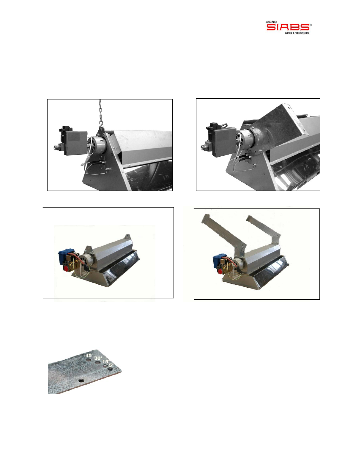
Positioning
The appliances can be installed on walls / pillars, or hanging at ceiling. On request, we can
provide supports (S hooks and chains are excluded) for suspension at ceiling (picture 1), or
wall brackets to fix the heaters on the wall (picture 2) with different angled positions for
the heater. The following figures will show you how to install all types of appliances.
picture 1 – Installation with chains DC picture 2 – Installation at wall DC
picture 1 – Installation with chains DCeco picture 2 – Installation at wall DCeco
The brackets provided by SIABS allow an angle of installation variable once mounted on a wall
or pillar, in order to get a better heat distribution (picture 3, supports for DCeco version)
picture 3 – different angles : 5° , 15° , 30° , 45°
Manu_ENG_DC_DCeco_rev. 0_04_2012 page 9
IMPORTANT!
at each side of the burner 2 hooks are provided with M8 inserts, for fixing to a wall or
at ceiling by means of appropriate brackets (not supplied, available on request); do not
create other anchor points on the carpentry of the heater and in particular on
the body burner, but use only those designed by the factory
we recommend SIABS original brackets for installation of the radiant heaters
for fixing brackets on a wall or pillars assess the consistency of walls and the load
applied, in order to choose the correct anchors to be used; in any case provide
blocks with M8 screw minimum diameter (e.g. anchor Fischer TA - M in steel, with M8
screw)
IMPORTANT: appliances must be installed in horizontal position, contact us in case of
different inclination. In any case, the system of fixing / suspension must allow thermal
expansion of appliance (some millimetres depending on the model).
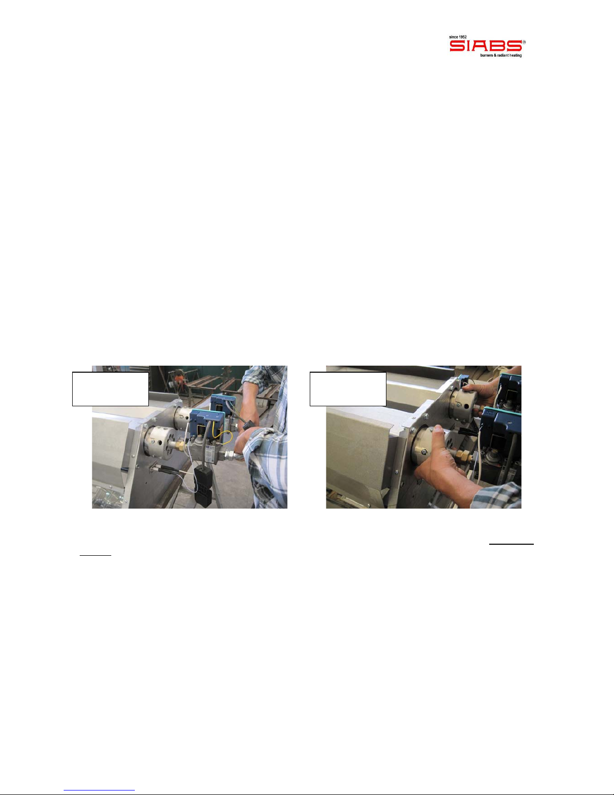
Handling
During extraction of the appliances from package and for all operations of handling till final
place of installation, gas valves / flame controls or flanges of the injection group must NOT be
used as lifting points, as in the pictures below.
Appliances must be taken at the installation point / height inside its package or using M8
inserts: all other parts of the appliances are NOT designed to withstand its weight.
NO !! NO !!
 Loading...