

Shyam Telecom IRD55FB 30 70 User Manual
,
Antenna – Electronic
Communication Systems
R-30 Series Repeater
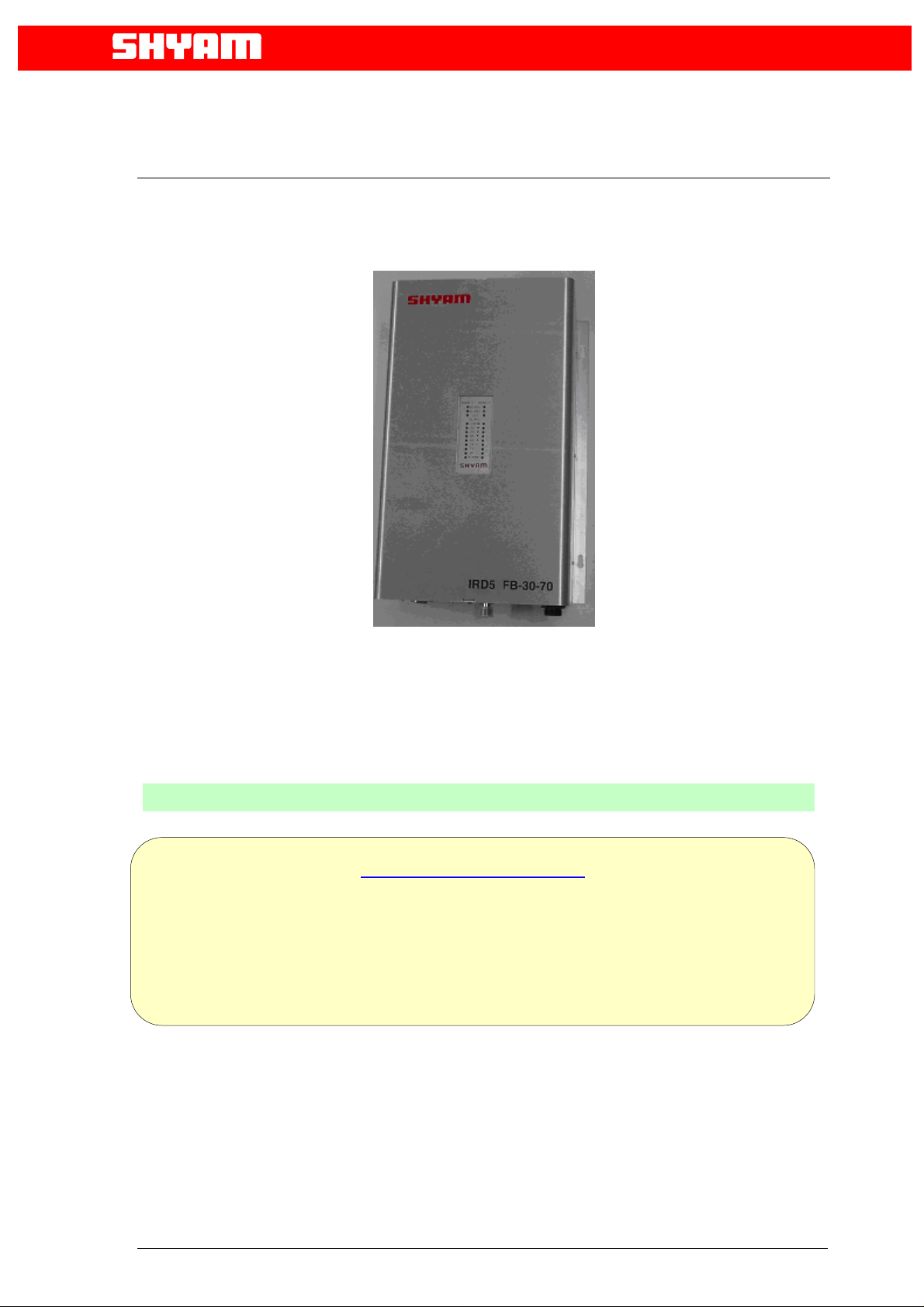
Model No. IRD55FB-30-70
OOPPEERRAATTIIOONN MMAANNUUAAL
L
Two Sub-bands in Cellular (A” A+A’ or B+B’)
Up To Three Sub-Bands in PCS-1900
Doc No 5700 9006 530 VERSION 1.1 04 Mar
The information contained herein is proprietary to Shyam Telecom Limited. Use
or disclosure of this document or the information contained herein, for any purpose
other than that for which it was furnished is not permitted or it shall not be disclosed
or divulged to any third Party without the prior written cons ent of Shyam Telecom
Limited.
DDBB--55RR--3300
Dual Band Repeater
Proprietary Information
2005
Mktg. Office:
SHYAM Telecom Ltd.
C-138, Naraina Industrial Area, Phase-I, New Delhi-110028 (INDIA)
Tel: 91 11 2579 8544 Fax: 91 11 2579 0726 Email:
repeater@shyamtelecom.com
1

Antenna – Electronic
Communication Systems
Contents
PREAMBLE.......................................................................................3
1.0 About the manual........................................................................3
2.0 Important Safety Information.......................................................3
3.0 Introduction: Repeater Theory / Background..............................4
4.0 Description of DB-5R-30 Repeater Kit......................................5
4.1 System Block Diagram...................................................................6
4.2 Contents of delivery: ...................................................................7
4.2.1 DONOR ANTENNA..................................................................7
Figure 4.2.1 : Donor Antenna..............................................................7
4.2.2 CONVERTER MODULE..........................................................7
Figure 4.2.2 : Converter Module........................................................7
4.2.3 Controller module (Supervisory) ..............................................8
Figure 4.2.3 : Monitoring and controller module.................................8
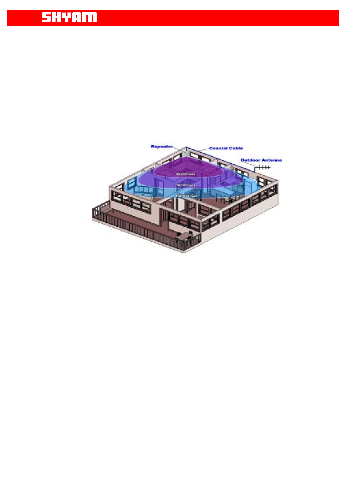
5.0 Typical In-Building Coverage......................................................9
6.0 Installing the DB-5R-30...............................................................9
6.1 Pre-installation Considerations ...................................................9
6.2 Installation Tools.......................................................................10
6.4 Display Details of DB-5R-30 .....................................................12
6.5 In-Building Coverage Problems ................................................13
6.6 Antenna Isolation ......................................................................14
6.7 Additional Parts you will need (Optional)....................................15
Coaxial Cable Recommendations ..............................................15
Trouble shooting procedure ...............................................................16
Technical Specification: Repeaters DB-5R-30...................................17
2

Antenna – Electronic
Communication Systems
PREAMBLE
In cellular systems repeaters are used, to enhance the coverage of a base station
in a region where, due to topological conditions, poor field strengths disable
communication. SHYAM is a leading manufacturer of repeaters. These repeaters
provide excellent electrical characteristics, are lightweight and easy to install.
Any intervention has to be performed by authorized persons only. If you need
technical assistance, please contact at the following address:
SHYAM Telecom Ltd.
C-138, Naraina Industrial Area, Phase-I, New Delhi-110028 (INDIA)
Tel: 91 11 2579 8544 Fax: 91 11 2579 0726 Email:
Under consideration of all references given in this manual, the repeater should be
taken into service without any complications and should operate trouble free for a
long time.
repeater@shyamtelecom.com
However we have country wide after sales support network to assist you if required.
Please visit to our web site www.shyamtelecom.com
sales support offices.
for our country wide after
1.0 About the manual
The “Operation manual” is intended to be used for SHYAM DB-5R-30 repeater
installation. It contains the general guidelines for the field engineers /technicians.
Read carefully before starting the DB-5R-30 repeater installation.
2.0 Important Safety Information
The DB-5R-30 repeater has been designed for maximum safety when installed
and operated according to the instructions in this manual. Refer to all safety
instructions as per the antenna installation instruction sheets.
Do not bypass any of the safety features with the equipment provided, nor operate
the system in an inappropriate environment.
WARNING! Installation of antennas near power lines is dangerous. For your
safety, follow all installation directions and keep safe distance from any high
voltage power lines that could result in shock or loss of life.
3
Antenna – Electronic
r
emissio
Communication Systems
WARNING! This equipment complies with FCC & IC radiation exposure limits
set forth for an uncontrolled environment. This transmitter must not be colocated or operating in conjunction with any other antenna or transmitter. For
mobile or fixed location transmitters, the minimum separation distance is
greater than 40 cm, even if calculations indicate that the MPE distance would
be less.
Additional wiring required to install the DB-5R-30 system should comply with
national or local governing Electrical Codes. Indoor RF coaxial cable installations
should comply with local Electrical Code requirements. The DB-5R-30 repeater
should only be installed in restricted access areas such as dedicated equipment
rooms or closets.
The DB-5R-30 repeater is designed for indoor application; the housing is not
waterproof. So please keep it away from water, rain and any chemical liquid.
Do discharge the static before you touch the connectors of the repeater.
Do not open the module inside the repeater unless you are authorized.
The power supply unit in the DB-5R-30 repeater is supplied from the mains
(primary AC power) that contains dangerous voltage level which will cause electric
shock, Please turn off the mains before you install / uninstall the repeater.
The primary AC power should be in the range of AC90-240V, 50/60Hz. Repeater
will be damaged if the primary AC power is out of the range.
The RF electric performance of the DB-5R-30 Cellular / PCS repeate
conforms to ETSI requirement of the inter modulation and spurious
n. It avoids the interference problem.
3.0 Introduction: Repeater Theory / Background
In mobile cellular communication system, repeaters provide the radio frequency
(RF) coverage to areas, which either lack signal, or the required signal strength for
adequate mobile phone performance. To the typical user, this translates to the
inability to place or receive mobile phone calls in or out of the area, and in most
cases will result in a dropped call while entering into the poor coverage area.
Insufficient wireless coverage can occur both indoors and outdoors, and may
include indoor areas such as office buildings, parking garages, apartment buildings,
shopping malls, and residential homes. Out door areas are degraded by
geographic topologies such as mountains, valleys, dense foliage and high rising
urban landscapes which can easily degrade or obstruct the cell site’s signal from
4
Antenna – Electronic
Communication Systems
the mobile phone.
The weak coverage problem can be solved by installing an active repeater system,
designed for use in a multitude of installation configurations. Repeater systems
provide an effective solution by redirecting, filtering and amplifying the available
signal at the donor antenna, into the weak coverage area, through a properly
selected interior coverage antenna. The illumination of the weak coverage area
allows the user’s handset to operate as intended within the building or weak
coverage area, while maintaining the user’s call clarity and quality, which reduces
service complaints and potential subscriber churn.
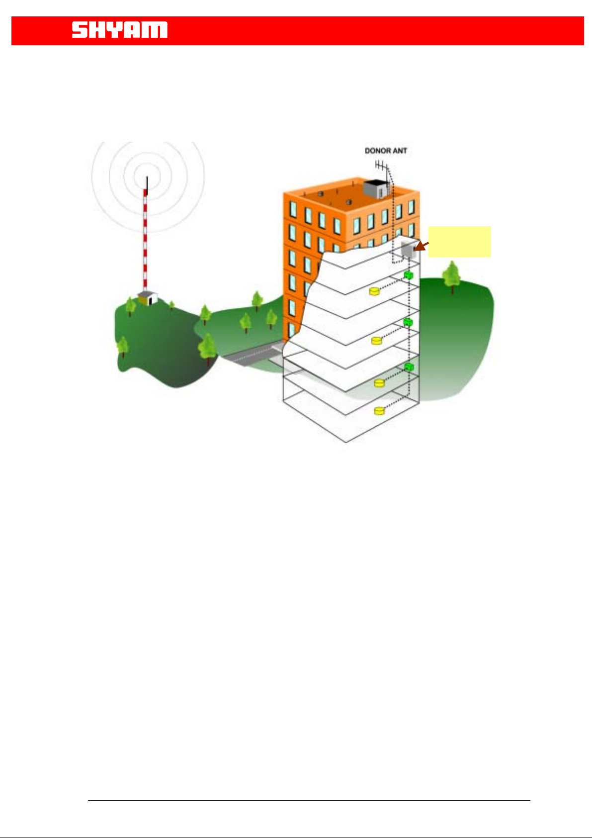
Figure 1: Typical Repeater/Coverage Configuration
4.0 Description of DB-5R-30 Repeater
The DB-5R-30 repeater system contains a high power, automatic power control,
bi-directional amplifier (BDA) used along with a donor antenna (Optional outdoor
yagi antenna) and server antenna ( Optional indoor omni directional antenna),
specifically designed for interior configurations. The donor antenna must be pointed
toward the cell of the base station from where the signal is to be picked up and is
usually mounted on the exterior of the building so as to receive the maximum
forward signal level from the base station. The indoor antenna is specifically
designed to blend into the ceiling of a typical office providing RF signal in all
directions downward and outward from the installation point. For in-building
configurations requiring higher gain or directional RF signal, such as a long hallway
or corridor, a medium gain directional antenna may cover the area best by
mounting the antenna to the opposing wall, where coverage is required.
5
p
4.1 Typical application
Antenna – Electronic
Communication Systems
DB5R30
Re
eater
6
 Loading...