

Shyam Falcon SM200 Series, Falcon SM201, Falcon SM241W, Falcon SM202, Falcon SM242 Quick Start Manual
NETWORKS
www.shyamnetworks.com
Falcon SM200
Series Camera
Quick Start Guide
For advanced settings and more detailed information, download the user
manual from www.shyamnetworks.com.
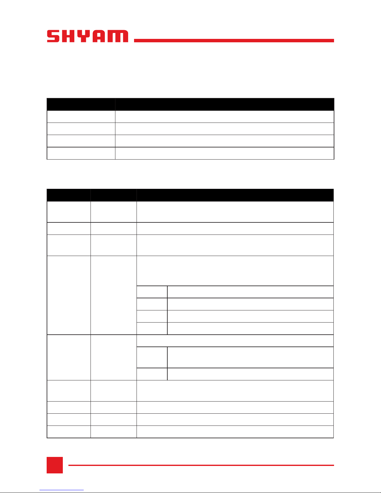
Package Contents
Camera with Mount Base 1
Flexible Clamp with Fixing Screws 1
Power Adapter 1
Wall Mounting Screws 1
Terminal Block for Alarm I/O 1
Quick Start Guide 1

3
NETWORKS
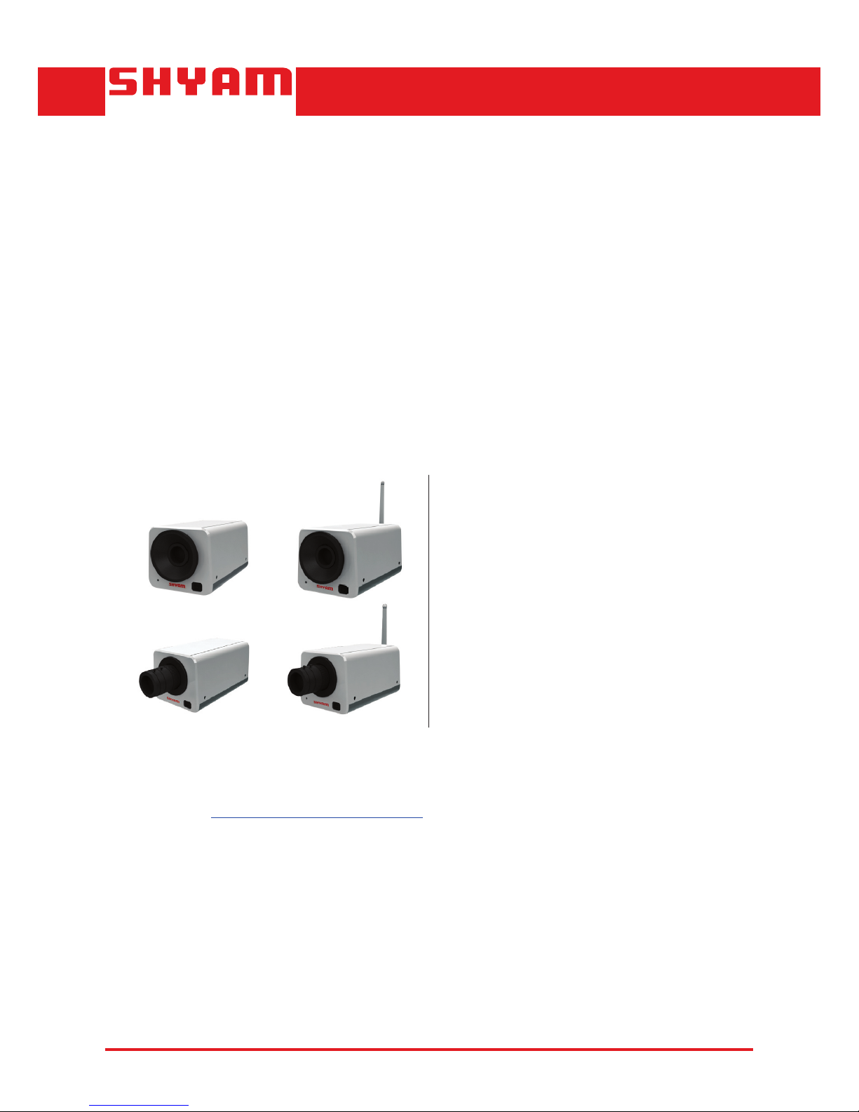
SM200
SM202
SM201
SM242W
SM241W
3
3
22
2
2
1
1
7
6
5
4
10
14
15
11
13
12
8 9
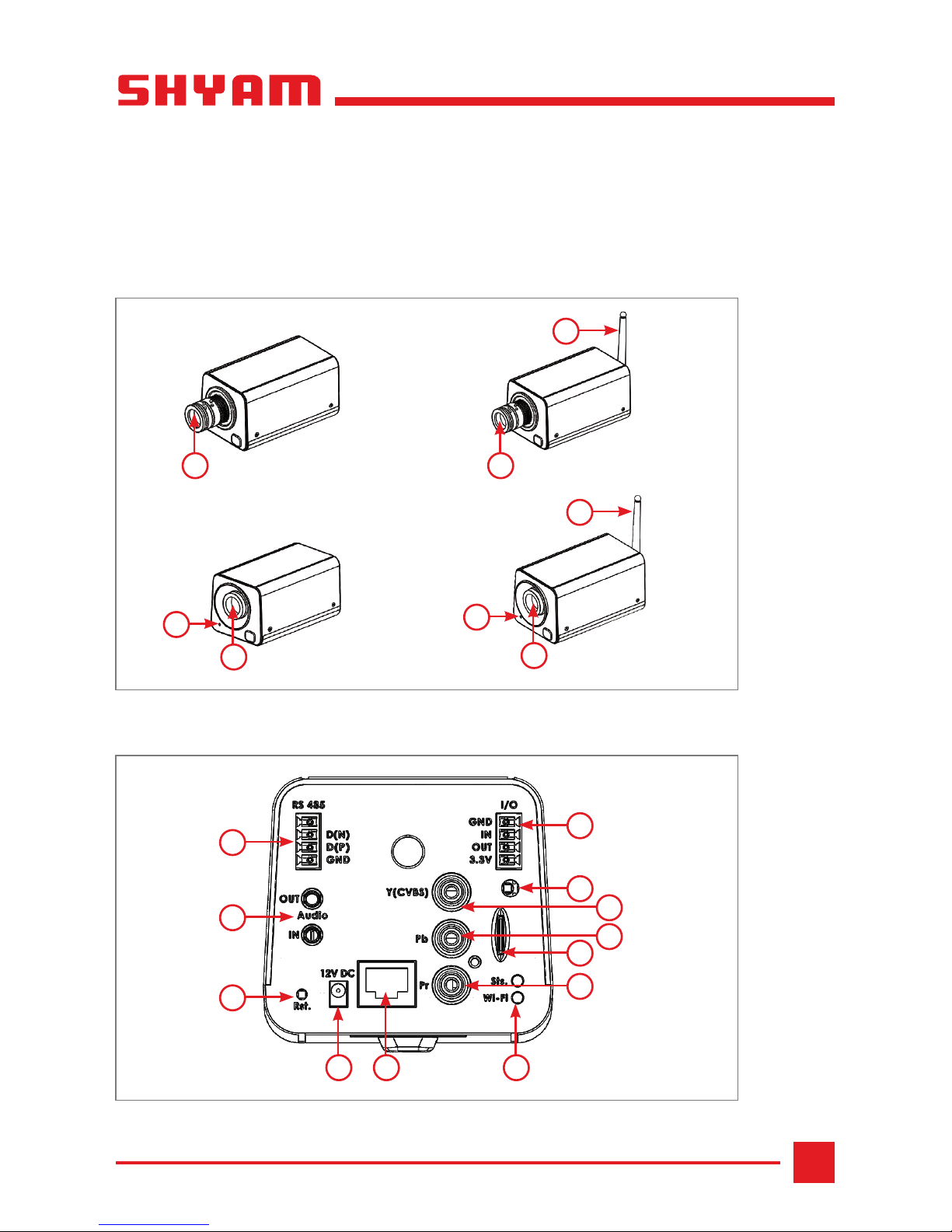
1. Hardware Overview
Front View
Rear View
Figure 1
Figure 2
4
NETWORKS
SM200
LABEL NO. INTERFACE DESCRIPTION
1 Microphone Built-in microphone present on the front panel, which
records sound. Used to capture audio from the vicinity.
2 Lens Camera lens depending on the model.
3 Wi-Fi
Antenna
To boost the signal of the camera’s wireless network
depending on the model.
4 RS 485 RS-485 is a communication protocol that allows serial
connection between devices. In Falcon, pins listed below can
be used to connect external PTZ module.
First Pin Not used.
D(N) Indicates data negative.
D(P) Indicates data positive.
GND Indicates ground for reference.
5 Audio Provides audio input and output.
OUT To connect external speaker for providing audio as
output.
IN To connect external microphone for capturing audio.
6 Rst. Used only for service and debug purposes. User should not
use this switch.
7 12V DC DC inlet to provide an external power supply.
8 LAN Port One Ethernet port providing connection through Cat5e cable.
9 LEDs Indicates the working status of the camera.
Available Models
Interface Description
MODEL DESCRIPTION
SM201 CS mount wired (PoE) and HD camera
SM241W CS mount wired (PoE) and wireless HD camera
SM202 4x Zoom wired (PoE) and HD camera
SM242 W 4x Zoom wired (PoE) and wireless HD camera
 Loading...