

Page 1

XPC User Guide
For the : SN27P2
Page 2

Statement of Shuttle Mainboard via the EMI Test
Shuttle mainboards have been via the EMI test in terms of series of regulations: EN55022/CISPR22/
AS/NZS3548 Class B, EN55024 (1998/AS/NZS), EN4252.1 (1994), EN61000, ANSI C63.4 (1992),
CFR47 Part 15 Subpart B, and CNS13438 (1997). The items tested are illustrated as follows:
(A) Voltage: AC 110V/60HZ & AC 230V/50HZ
(B) Tested Product Information:
Product Name: PC Mainboard
Status: Sample
Model Name: SN27P2
S/N: N/A
CPU:
External Frequency: 200 MHz
AMD AthlonTM 64x2 : 5000+
Clear CMOS button: one port
USB 2.0 Port: eight ports with 4 pins respectively
1394 Port: one port with 6 pins respectively,one port with 4 pins.
LAN Port: one port with 8 pins (10Mbps/100Mbps/1000Mbps)
Mic-In & Line-In & Earphone Ports: one port for each
Center/Bass-Out Port: one port
Surround-Out Port: one port
Surround-Back Port: one port
Front-Out Port: one port
SPDIF-Out (Coaxial) Port: one port
SPDIF-Out (Optical) Port: one port
SPDIF-In (Optical) Port: one port
DIMM Memory (optional): DDRII 533/667 1GB *4
Power Cable: Detachable and Shielded (with a GND pin)
All CPUs have completely been tested, and values offered by the worst EMI combination of
CPU external frequency are listed as follows:
Test Mode External Frequency CPU CPU Open/Close
1 200MHz AMD Athlon
TM
64X2 5000+ Close
2 200MHz AMD Athlon
TM
64X2 5000+ Open
Page 3

(C) Remedy for the Tested Product & Its EMI Interference:
Remedy: N/A
EMI Interference:
Crystal : 32.768 KHz(X1)/ 25 MHz(X2)/ 24.576 MHz(X1)
(D) Supported Host Peripherals:
Host Peripheral Product Name Model Name
# 1 Case SN27P2
# 2 Power Supply PC43I3503
# 3 Serial ATA II HITACHI HDS728080PLA380
# 4 Serial ATA II HITACHI HDS728080PLA380
# 5 DVD Dual Player CR40
# 6 Gigabyte 7800GTX GV-NX78X256V-B
# 7 Gigabyte 7800GTX GV-NX78X256V-B
(E) Notices for Assembling Computers:
1. Cases should be made of iron or other metal that has good electric conductivity.
2. Cylinders in a case should be made of metal, and as having a mainboard mounted
in a case, make sure screws are all utilized and fastened on a mainboard.
3. An I/O shielding should be contacted with I/O metallic parts of a mainboard.
4. Cables should appropriately be arranged and fixed in a case. Follow instructions:
Ø Leave IDE cables not crossed upon CPU and SDRAM;
Ø Leave power cables minimum in length, and not crossed upon a mainboard;
Ø Leave CPU fan cables minimum in length, and not near CPU;
Ø Leave cables on panels and other spare cables tied in a computer case.
5. Make sure an EMI shielding attached to a case has properly been installed.
6. Make sure a 5.25" or 3.5" FDD and screws are fastened to an EMI shielding.
7. Make sure a case is closely in contact with EMI connected points.
8. Make sure there is no cleft in a case which is not deformed.
9. Make sure a PCI or AGP door is bound to a case.
10. Make sure cables of other devices (fans or some others) are fixed in a case.
Page 4

Shuttle
®
XPC Installation Guide
Copyright
Copyright© 2006 by Shuttle® Inc. All Rights Reserved.
No part of this publication may be reproduced, transcribed, stored in a retrieval system,
translated into any language, or transmitted in any form or by any means, electronic,
mechanical, magnetic, optical, chemical, photocopying, manual, or otherwise, without prior
written permission from Shuttle® Inc.
Disclaimer
Shuttle® Inc. shall not be liable for any incidental or consequential damages resulting from
the performance or use of this product.
This company makes no representations or warranties regarding the contents of this manual. Information in this manual has been carefully checked for reliability; however, no
guarantee is given as to the correctness of the contents. In the interest of continued product
improvement, this company reserves the right to revise the manual or include changes in
the specifications of the product described within it at any time without notice and without
obligation to notify any person of such revision or changes. The information contained in
this manual is provided for general use by customers.
This device complies with Part 15 of the FCC Rules, Operation is subject to the following
two conditions:
1. This device may not cause harmful interference.
2. This device must accept any interference received, including interference that may
cause undesired operation.
Trademarks
Shuttle is a registered trademark of Shuttle Inc.
Intel and Pentium are registered trademarks of Intel Corporation.
PS/2 is a registered trademark of IBM Corporation.
AWARD is a registered trademark of Award Software Inc.
Microsoft and Windows are registered trademarks of Microsoft Corporation.
General Notice
Other brand and product names used herein are for identification purposes only and may
be trademarks of their respective owners.
Page 5

Installation Notices
Do not place this device underneath
heavy loads or in an unstable position.
Do not expose this d evice to high
levels of direct sunlight, hig h-humidity
or wet conditions.
Do not use or expose this device
around magn etic fields as magnetic
interference may affect the
performance of the device.
Do not blo ck the air vents to this
device or impede the airflow in
any way.
CAUTION
Incorr ectly replacing the battery may damage this computer. Replace only with
the same or equivalent as recommended by Shuttle. Di spose of used batteries
accordi ng to the manufacturer's instructions.
Safety Informat ion
Read the followi ng precautions before setting up a Shuttle XPC.
Page 6

TABLE OF C ONTENTS
1 Driver and Software Installation........................................................................... 1
1.1 Mainboard Driver CD..................................................................................... 2
1.1.1 Install Mainboard Software..................................................................... 2
Appendix .................................................................................................................. 3
Enter the BIOS ..................................................................................................... 3
THE MAIN MENU ................................................................................................. 4
Standard CMOS Features.............................................................................. 6
Advanced BIOS Features ............................................................................... 9
Advanced C hipset Features ......................................................................... 13
Integrated Per ipherals .................................................................................. 15
Power Management Setup ........................................................................... 18
PnP/PCI Configur ations............................................................................... 21
PC Health Status.......................................................................................... 23
Frequency/Vol tage Control ........................................................................... 25
Load Fail-Safe Defaults................................................................................ 27
Load Optimized Defaults .............................................................................. 27
Set Supervisor/User Passw ord..................................................................... 27
Save & Exi t Setup ........................................................................................ 28
Exit Without Saving ...................................................................................... 2 8
Page 7
1
English
< 1.1 Mainboard Driver CD
The Mainboard Driver CD contains all the motherboard driver necessary to optimize
the performance of this XPC in a Windows(R) OS. Install these drivers after installing
Microsoft(R) Windows(R).
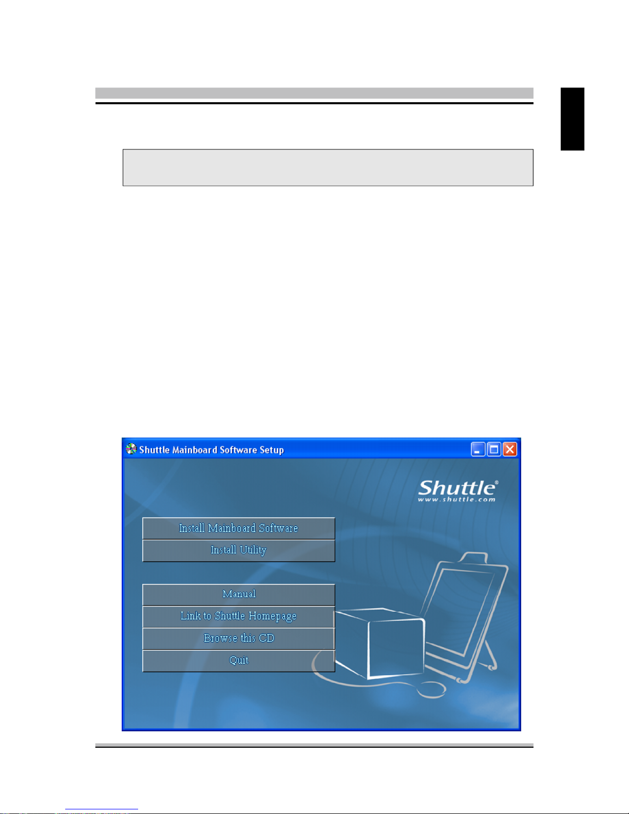
Navigation Bar Description :
F Install Mainboard Software - DirectX9 Utility, nVIDIA Chipset Driver,
High Definition Driver,nVIDIA USB 2.0 Driver,
nVIDIA Raid Tools Driver (Win2000 Only ).
F Install Utility - Install Acrobat Reader, WinFlash Utility.
F Manual - SN27P2 user's guide and nVIDIA manual in PDF format.
F Link to Shuttle Homepage - Link to shuttle website homepage.
F Browse this CD - Allows you to see contents of this CD.
F Quit - Close this CD.
Note : The CD contents attached in SN27P2 mainboard are subject to
change without notice.
1 Driver and Software Installation
Page 8

2
English
< 1.1.1 Install Mainboard Software
Insert the attached CD into your CD-ROM drive. The CD AutoRun screen should
appear. If the AutoRun screen does not appear, double click on Autorun icon in My
Computer to bring up Shuttle Main-board Software Setup screen.
Click the “Install Main-board Software“ bar. Individually install the following drivers.
F Install DirectX9 Utility
F Install nVIDIA Chipset Driver
F Install High Definition Driver
F Install nVIDIA USB 2.0 Driver
F Install nVIDIA Raid Tools Driver ( Win2000 Only)
Page 9

3
English
BIOS Settings
The SN27P2 BIOS ROM has a built-in Setup program that allows users to modify basic
system configuration. This information is stored in battery-backed RAM so that it retains Setup information even if the system power is turned off.
The system BIOS manages and executes a variety of hardware related functions
including:
System date and time
Hardware execution sequence
Power management functions
Allocation of system resources
Enter the BIOS
To enter the BIOS (Basic Input / Output System) utility, follow these steps:
Step1. Power on the computer. The system will perform its POST (Power-On
Self Test) routine checks.
Step2. Press the <Del> key immediately, or at the following message:
Press DEL to enter SETUP, or simultaneously press <Ctrl>,<Alt>,
<Esc> keys
Note 1. If you miss the train of words mentioned in step2 (the message disap-
pears before you can respond) and you still wish to enter BIOS Setup,
restart the system and try again by turning the computer OFF and
ON again or by pressing the <RESET> switch located at the
computer’s front-panel. You may also reboot by simultaneously
pressing the <Ctrl>,<Alt>, <Del> keys simultaneously.
Note 2. If you do not press the keys in time and system does not boot, the
screen will prompt an error message, and you will be given the
following options:
"Press F1 to Continue, DEL to Enter Setup”
Step3. When you enter the BIOS program, the CMOS Setup Utility will display the
Main Menu, as shown in the next section.
Appendix
Page 10

4
English
The Main Menu
Once you enter the AwardBIOS(tm) CMOS Setup Utility, the Main Menu
will appear on the screen. The Main Menu allows you to select from several setup functions and two exit choices. Use the arrow keys to select
among the items and press <Enter> to accept and enter the sub-menu.
Note that a brief description of each highlighted selection appears at the
bottom of the screen.
Setup Items
The main menu includes the following main setup categories. Recall that
some systems may not include all entries.
Standard CMOS Features
Use this menu for basic system configuration.
Advan ced BIOS Features
Use this menu to set the Advanced Features available on your system.
Advan ced Chipset Features
Use this menu to change the values in the chipset registers and optimize
your system's performance.
Integrated Peripherals
Use this menu to specify your settings for integrated peripherals.
Power Management Setup
Use this menu to specify your power management settings.
PnP / PCI Configurations
This entry appears if your system supports PnP / PCI.
Page 11

5
English
PC Healt h Status
This entry displays the current system temperature, Voltage, and FAN
settings.
Frequency/Voltag e Control
Use this menu to specify your settings for Frequency/Voltage control.
Load Fail-Saf e Defaults
Use this menu to load the BIOS default values for the minimal/stable performance of your system to operate.
Load Optimized Defaults
Use this menu to load the BIOS default values that are factory-set for optimal system operation. While Award has designed the custom BIOS to
maximize performance, the factory has the right to change these defaults
to meet users' needs.
Set Supervisor / User Password
Use this menu to change, set, or disable password protection. This allows
you to limit access to the system and Setup, or only to Setup.
Save & Exit Setup
Save CMOS value changes in CMOS and exit from setup.
Exit Without Savin g
Abandon all CMOS value changes and exit from setup.
Page 12

6
English
@ Standard CMOS Features
The items in the Standard CMOS Setup Menu are divided into several
categories. Each category includes none, one or more than one setup
items. Use the arrow keys to highlight the item and then use the <PgUp>
or <PgDn> keys to select the value you want in each item.
Date
<Month> <DD> <YYYY>
Set the system date. Note that the 'Day' automatically changes when
you set the date.
Time
<HH : MM : SS>
The time is converted based on the 24-hour military-time clock.
For example, 5 p.m. is 17:00:00.
IDE Channel 0 Master/Slave
Options are in its sub-menu.
Press <Enter> to enter the sub-menu of detailed options.
Drive A
Select the type of floppy disk drive installed in your system.
Ø The choice: None, 360K, 5.25 in, 1.2M, 5.25 in, 720K, 3.5 in,
1.44M, 3.5 in, or 2.88M, 3.5 in.
Halt On
Select the situation in which you want the BIOS to stop the POST
process and notify you.
Ø The choice: All Errors, No Errors, All, But Keyboard, All, But
Diskette, or All, But Disk/Key.
Page 13

7
English
Base/Extended/Total Memory
Theseitems are automatically detected by the system at start up time.
These are display-only fields. You can't make change to these fields.
******************************************************
IDE Adapters
The IDE adapters control the hard disk drive. Use a separate sub-menu
to configure each hard disk drive.
IDE HDD Auto-Detection
Press <Enter> to auto-detect HDD on this channel. If detection is
successful, it fills the remaining fields on this menu.
Ø Press Enter
IDE Channel 0 Master
Selecting 'manual' lets you set the remaining fields on this screen and
select the type of fixed disk. "User Type" will let you select the number of
cylinders, heads, etc., Note: PRECOMP=65535 means
NONE !
Ø The choice: None, Auto, or Manual.
Access Mode
Choose the access mode for this hard disk.
Ø The choice: CHS, LBA, Large, or Auto.
Capacity
Disk drive capacity (Approximated). Note that this size is usually slightly
greater than the size of a formatted disk given by a disk checking program.
Ø Auto-Display your disk drive size.
The following options are selectable only if the 'IDE Primary Master'
item is set to 'Manual'
Cylinder
Set the number of cylinders for this hard disk.
Ø Min = 0, Max = 65535
Head
Set the number of read/write heads.
Ø Min = 0, Max = 255
Page 14

8
English
Precomp
Warning: Setting a value of 65535 means no hard disk.
Ø Min = 0, Max = 65535
Landing zone
Set the Landing zone size.
Ø Min = 0, Max = 65535
Sector
Number of sector per track.
Ø Min = 0, Max = 255
******************************************************
Page 15

9
English
@ Advanced BIOS Features
This section allows you to configure your system for basic operation. You
have the opportunity to select the system's default speed, boot-up sequence,
keyboard operation, shadowing, and security.
CPU Feature
Options are in its sub-menu.
Press <Enter> to enter the sub-menu of detailed options.
K8 NPT C1E Support
This item is select K8 NPT C1E Support.
Ø The Choice: Disabled, SoftWare SMI or HareWare C1E.
AMD K8 Cool & Quiet control
This item is select AMD K8 Cool & Quiet Control.
Ø The Choice: Auto or Disabled.
Removable Device Proirity
Options are in its sub-menu.
Press <Enter> to enter the sub-menu of detailed options.
Hard Disk Boot Priority
This item allows you to select Hard Disk Book Device Priority.
Page 16

10
English
CD-ROM Boot Priority
This item allows you to select Hard Disk Book Device Priority.
Bios Write Protect
This item allows you to enable or disable the Bios Write Protect.
If you want to flash BIOS, you must set it [Disabled].
Ø The choice: Enabled or Disabled.
Virus Warning
Allows you to choose the VIRUS Warning feature for IDE Hard Disk boot
sector protection. If this function is enables and someone attempts to write
data into this area, BIOS will show a warning message on screen, and an
alarm beep.
Enabled Activates automatically when the system boots up, causing a
warning message to appear when anything attempts to access
the boot sector or hard disk partition table.
Disabled No warning message will appear when anything attempts to
access the boot sector or hard disk partition table.
Ø The choice: Enabled or Disabled.
CPU Internal Cache
All processors that can be installed in this mainboard use internal level 1
(L1) cache memory to improve performance. Leave this item at the default value for better performance.
Ø The choice: Enabled or Disabled.
External Cache
Most processors that can be installed in this system use external level 2
(L2) cache memory to improve performance. Leave this item at the default value for better performance.
Ø The choice: Enabled or Disabled.
Quick Power On Self Test
This item speeds up Power-On Self Test (POST) after you power on the
computer. If it is set to enabled, BIOS will shorten or skip some check
items during POST.
Ø The choice: Enabled or Disabled.
Page 17

11
English
First/Second/Third Boot Device
The BIOS attempts to load the operating system from the devices in the
sequence selected in these items.
Ø The Choice: Floppy, LS120, Hard Disk, CDROM, ZIP100, USB-FDD,
USB-ZIP, USB-CDROM, Legacy LAN, or Disabled.
Boot Other Device
Select Your Boot Device Priority.
Ø The choice: Enabled or Disabled.
Boot Up Floppy Seek
Seeks disk drives during boot-Up. Disabling speed boots up. Enabled tests
floppy drives to determine whether they have 40 or 80 tracks.
Ø The choice: Enabled or Disabled.
Boot Up NumLock Status
Selects power on state for NumLock.
Ø The choice: Off or On.
Typematic Rate Setting
Keystrokes repeat at a rate determined by the keyboard controller.
When this controller enabled, the typematic rate and typematic delay
can be selected.
Ø The choice: Enabled or Disabled.
Typematic Rate (Chars/Sec)
This item sets how many times the keystroke will be repented in a second
when you hold the key down.
Ø The choice: 6, 8, 10, 12, 15, 20, 24 or 30.
Typematic Delay (Msec)
Sets the delay time after the key is held down before it begins to repeat the
keystroke.
Ø The choice: 250, 500, 750 or 1000.
Security Option
Select whether the password is required every time the system boots or
only when you enter setup.
Page 18

12
English
System The system will not boot and access to Setup will be
denied if the correct password is not entered promptly.
Setup The system will boot, but access to Setup will be
denied if the correct password is not entered promptly.
Ø The choice: System or Setup.
Note : To disabled security, select PASSWORD SETTING at Main Menu,
and then you will be asked to enter password. Do not type anything and just press <Enter>; it will disable security.
Once the security is disabled, the system will boot, and you can
enter Setup freely.
HDD Security Freeze Lock
Selects enable/disable HDD Security Freeze Lock, Enable-prevents any
external application from locking Hard drive except for BIOS.
Ø The choice: Enabled or Disabled.
APIC Mode
Selects enable/disable IO APIC function.
Ø The choice: Enabled or Disabled.
MPS Version Control For OS
Selects the operating system multiprocessor support version.
Ø The choice: 1.1 or 1.4.
Page 19

13
English
@ Advanced Chipset Features
This section allows you to configure the system based on the specific features
of the installed chipset. This chipset manages bus speeds and access to system memory resources, such as DRAM and the external cache. It also coordinates communications between the conventional ISA bus and the PCI bus. It
states that these items should never need to be altered.
The default settings have been chosen because they provide the best operating conditions for your system. If you discovered that data was being lost
while using your system, you might consider making any changes.
K8 <--> SB HT Speed
This item allows you to set the HT Speed.
Ø The choice: Auto, 1x~5x.
K8<-->MCP55 HT Width
This item allows you to set the HT Width.
Ø The choice: 8 8 or 16 16.
DRAM Configuration
Options are in its sub-menu.
Press <Enter> to enter the sub-menu of detailed options.
Timing Mode
Ø The Choice: Auto or MaxMemClk.
DDRII Timing Item
Ø The Choice: Enabled or Disabled.
Page 20

14
English
SSE/SSE2 Instructions
This item allows you to enable/disable the SSE/SSE2 Instructions.
Ø The Choice: Enabled or Disabled.
System BIOS Cacheable
Select Enable allows caching of the system BIOS ROM at F000h-FFFFFh,
resulting in better system performance. However, if any program is written to this memory area, a system error may result.
Ø The Choice: Enabled or Disabled.
Page 21

15
English
@ Integrated Peripherals
Onboard IDE Device
Options are in its sub-menu.
Press <Enter> to enter the sub-menu of detailed options.
RAID Function Setup
Press <Enter> to enter the RAID Function Setup.
RAID Enable
This setting item need to be configued as “Enabled” in order that the
“SATA 1 Primary / Secondary and SATA 2 Primary / Secondary
RAID” setting item could be configuable.
ØThe Choice: Enabled or Disabled.
OnChip IDE Channel 0
The chipset contains a PCI IDE interface with support to two IDE channels.
Select Enabled to activate the primary IDE interface. select Disabled to
deactivate this interface.
Ø The Choice: Enabled or Disabled.
Primary Master/Slave PIO
The four IDE PIO (Programmed Input/Output) fields let you set a PIO mode
(0-4) for each of the four IDE devices that the onboard IDE interface
supports. Modes 0 through 4 provide successively increased performance.
In Auto mode, the system automatically determines the best mode for
each device.
Ø The choice: Auto, Mode 0, Mode 1, Mode 2, Mode 3, or Mode 4.
Page 22

16
English
Primary Master/Slave UDMA
Ultra DMA/100 implementation is possible only if your IDE hard drive
supports it and the operating environment includes a DMA driver (Windows 95 OSR2 or a third-party IDE bus master driver). If both of your hard
drive and your system software support Ultra DMA/100, select Auto to
enable BIOS support.
Ø The choice: Auto or Disabled.
Serial-ATA Controller
This item allows you to enable/disable the SATA transfer access.
Ø The choice: All Enabled, Disabled or SATA-1.
IDE Prefetch Mode
The onboard IDE drive interface support IDE prefetching for faster drive
access. If you install a primary and /or secondary add-on IDE interface, set
this field to Disabled if the interface does not support prefetching.
Ø The Choice: Enabled or Disabled.
IDE HDD Block Mode
Block mode is also called block transfer, multiple commands, or multiple
sector read/write. If your IDE hard drive supports block mode(most new
drivers do), select Enabled for automatic detection of the optimal number
of block read/write per sector the drive can support.
Ø The Choice: Enable or Disabled.
Onboard Device
Options are in its sub-menu.
Press <Enter> to enter the sub-menu of detailed options.
Init Display First
This item is used to determine initial device when system power on.
Ø The choice: PCI Slot or PCI-Ex Slot.
OnChip USB
This should be enabled if your system has a USB installed on the system
board and you want to use it.
Ø The choice: Desable, V1.1+V2.0 or V1.1.
HD Audio
This item allows you to control the HD Audio.
Ø The Choice: Auto or Disabled.
Page 23

17
English
MAC Lan
This item allows you to control the MAC Lan.
Ø The Choice: Auto or Disabled.
Onboard SuperIO Device
Options are in its sub-menu.
Press <Enter> to enter the sub-menu of detailed options.
Onboard FDC Controller
This item specifices onboard floopy disk drive controller. This setting
allows you to connect your floopy disk drives to the onboard floopy
connector.
Ø The Choice: Enable or Disabled.
Page 24

18
English
@ Power Management Setup
The Power Management Setup allows you to configure your system to
most effectively saving energy while operating in a manner consistent
with your own style of computer use.
ACPI Function
This item allows you to enable/disable the Advanced Configuration and
Power Management (ACPI).
Ø Always "Enabled".
ACPI Suspend Type
This item allows you to select sleep state when suspend.
Ø The choice: S1(POS) or S3(STR).
Power Management
This category allows you to select the type (or degree) of power saving
mode settings.
Min Saving Minimum power management.
Suspend Mode=15 min.
Max Saving Maximum power management.
Suspend Mode=1 min.
User Define Allows you to set each mode individually.
Suspend Mode= Disabled or 1 min ~15min.
Ø The choice: User Define, Min Saving or Max Saving.
Page 25

19
English
Video Off Method
This determines the manner in which the monitor is blanked.
V/H SYNC+Blank This selection will cause the system to turn off
the vertical and horizontal synchronization
ports and write blanks to the video buffer.
Blank Screen This option only writes blanks to the video buffer.
DPMS Supported Initial display power management signaling.
Ø The choice: V/H SYNC+Blank, Blank Screen or DPMS Supported.
HDD Power Down
The IDE hard drive will spin down if it is not accessed within a specified
length of time. Options are from 1 Min to 15 Min and Disable.
Ø The choice: Disabled or 1 Min ~ 15 Min.
HDD Down In Suspend
The item allows you to enabled or disabled the HDD Down In Suspend.
Ø The choice: Enabled or Disabled.
Soft-Off By PBTN
Pressing the power button for more than 4 seconds forces the system to
enter the Soft-Off state when the system has " hung".
Ø The choice: Delay 4 Sec or Instant-Off.
WOL(PME#) From Soft-Off
If this item sets to Enable, the system power will be turned on when the
LAN port receives an incoming signal. You have to connect the fax/modem to the mainboard Wake On LAN connector for this feature to work.
Ø The choice: Enabled or Disabled.
MAC Resume from S4/S5
If this item sets to Enable, the system power will be turned on when the
LAN port receives an incoming signal. You have to connect the fax/modem to the mainboard Wake On LAN connector for this feature to work.
Ø The choice: Enabled or Disabled.
Page 26

20
English
Power-On by Alarm
When set to Enabled, the following three fields become available and
you can set the month, date (day of the month), hour, minute and second
to turn on your system.
Ø The choice: Enabled or Disabled.
Day of Month Alarm
This item selects the alarm Day of Month.
Ø The choice: 0~31.
Time (hh : mm : ss) Alarm
This item selects the alarm Time.
[hh] Ø Key in a DEC number: Min=0, Max=23.
[mm/ss] Ø Key in a DEC number: Min=0, Max=59.
PWRON After PWR-Fail
This item allows you to select power on function when power fail.
Ø The choice: Former-Sts, Off or On.
Page 27

21
English
This section describes the configuration of PCI bus system. PCI or Personal Computer Interconnection is a system which allows I/O devices to
operate at the speed CPU itself keeps when CPU communicating with its
own special components.
This section covers some very technical items, and it is strongly recommended that only experienced users should make any changes to the
default settings.
Reset Configuration Data
Normally, you leave this field Disabled. Select Enabled to reset Extended
System Configuration Data (ESCD) when you exit from Setup if you have
installed a new device or software and the system reconfiguration has
caused such a serious conflict that the operating system can not boot.
Ø The choice: Enabled or Disabled .
Resource controlled By
The Award Plug-and-Play BIOS has the capacity to automatically configure all of the boot and Plug-and-Play compatible devices. However, this
capability means absolutely nothing unless you are using a Plug-and-Play
operating system such as Windows 95.
If you set this field to "manual" , choose specific resources by going into
each of the sub-menu that follows this field (a sub-menu is proceeded by
a ">").
Ø The choice: Auto(ESCD) or Manual.
@ PnP/PCI Configurations
Page 28

22
English
IRQ Resources
When resources are controlled manually, assign each system interrupt a
type, depending on the type of device using the interrupt.
IRQ3/4/5/7/9/10/11/12/14/15 assigned
This item allows you to determine the IRQ assigned to the ISA bus and is
not available to any PCI slot. Legacy ISA for devices is compliant with the
original PC AT bus specification; PCI/ISA PnP for devices is compliant
with the Plug-and-Play standard whether designed for PCI or ISA bus
architecture.
Ø The choice: PCI Device or Reserved.
PCI/VGA Palette Snoop
It determines whether the MPEG ISA/VESA VGA Cards can work with
PCI/VGA or not. If you have MPEG ISA/VESA VGA Cards and PCI/VGA
Card worked, Enable this field. Otherwise, please Disable it.
Ø The choice: Enabled or Disabled.
** PCI Express relative items **
Maximum Payload Size
Set maximum TLP payload size for the PCI Express devices.
The unit is byte.
Ø The choice: 128, 256, 512, 1024, 2048 or 4096.
Page 29

23
English
@ PC Health Status
Advanced CPU Fan Setting
Set the CPU Fan Speed.
ØThe choice : Smart Fan, Noise Control - U Low, Noise Control - Low,
Noise Control - Mid, Noise Control - Full,
Temp Control - 40oC, Temp Control - 45oC,
Temp Control - 50oC, Temp Control - 55oC,
Temp Control - 60oC.
Smart Fan : The CPU fan speed will be increased when the temperature
of CPU is raising up. Upon the temperature raising up to 80oC,
the CPU fan will be full speed.
Noise Control-U Low : When the CPU fan being set up as ULTRA LOW
and the temperature of CPU is raising up to 80oC,
the CPU fan being full speed.
Noise Control-Low : When the CPU fan being set up as LOW and the
temperature of CPU is raising up to 80oC, the CPU
fan being full speed.
Noise Control-Mid : When the CPU fan being set up as Mid and the
temperature of CPU is raising up to 80oC, the CPU
fan being full speed.
Noise Control-Full : CPU fan full speed.
Temp Control-45oC : When the CPU fan being set up as auto-modified,
the temperature of CPU will be remained as 45oC.
Page 30

24
English
Temp Control-45oC : When the CPU fan being set up as auto-modified,
the temperature of CPU will be remained as 45oC.
Temp Control-50oC : When the CPU fan being set up as auto-modified,
the temperature of CPU will be remained as 50oC.
Temp Control-55oC : When the CPU fan being set up as auto-modified,
the temperature of CPU will be remained as 55oC.
Temp Control-60oC : When the CPU fan being set up as auto-modified,
the temperature of CPU will be remained as 60oC.
Note : Before manually modifying the CPU fan setting, please make
sure fan connectors are plug into the correct fan connector
designations on the mainboard.
System Fan Setting
Set the System Fan.
ØThe choice : Ultra Low, Low, Mid or Full.
LED Bright Setting :
Set the LED Bright.
ØThe choice : 0%, 25%, 37.5%, 50%, 62.5%, 75%, 87.5% or 100%.
CPU Voltage
Chipset Voltage
+3.3V VIN
+5V VIN
+12V VIN
-12V VIN
RAM Voltage
5V SBVIN
Voltage Battery
CPU Temperature
System Temperature
CPU Fan Speed
Fan 2 Speed
Fan 3 Speed
Fan 4 Speed
SYSTEM Fan Speed
Warning : It is Strongly reco-mmended to
disable CPU Fan Auto Guardian
feature, if you wish to use other
fan cooler, allowing the fan to
run at its default speed.
Page 31

25
English
@ Frequency/Voltage Control
******CPU******
CPU Clock Multiplier
This item allows you to auto enable/disable a CPU Clock Multiplier.
Ø The choice: Auto or 4.0x~25.5x.
CPU Frequency
This item allows you to enable or disable the spread spectrum modulation.
Ø The choice: 200~300.
****** Spectrum******
CPU Spread Spectrum
This item allows you to enable or disable the CPU spread spectrum.
Ø The Choice: Enabled or Disabled.
PCIE Spread Spectrum
This item allows you to enable or disable the PCIE spread spectrum.
Ø The Choice: Enabled or Disabled.
SATA Spread Spectrum
This item allows you to enable or disable the SATA spread spectrum.
Ø The Choice: Enabled or Disabled.
Page 32

26
English
HT Spread Spectrum
This item allows you to enable or disable the HT spread spectrum.
Ø The Choice: Enabled or Disabled.
****** Voltage ******
CPU Voltage
This item allows you to set CPU Voltage.
Ø The choice: 0.800V~1.525V or Auto.
RAM Voltage
This item allows you to set RAM Voltage.
Ø The choice: Auto, 1.90V, 1.95V or 2.00V.
ChipSet Voltage set
This item allows you to set ChipSet Voltage.
Ø The choice: Auto, 1.55V or 1.60V.
Page 33

27
English
@ Set Supervisor/User Password
Steps to set supervisor/user password are described as follows:
@ Load Fail-Safe Defaults
When you press <Enter> on this item, you will get a confirmation
dialog box with a message similar to:
Load Fail-Safe Defaults (Y/N) ? N
Pressing 'Y' loads the BIOS default values for the most stable, minimal
performance system operations.
@ Load Optimized Defaults
When you press <Enter> on this item, you will get a confirmation
dialog box with a message similar to:
Load Optimized Defaults (Y/N) ? N
Pressing 'Y' loads the default values that are factory-set for optimal
performance system operation.
Page 34

28
English
New Password Setting:
1. Press the <Enter> key. A dialog box appears to ask you to “Enter password: “.
2. Key in a new password.
The password can not be over eight characters or numbers.
3. The system will then request you to confirm the new password by asking you to
key in the new password again.
4. Once the confirmation is completed, new code is in effect.
No Password Setting:
5. If you want to delete the password, just press the <Enter> key instead of
typing a new password. Follow the procedure as above.
If You Forget Password:
6. If you forget your password, you must turn off the system and clear CMOS.
Please refer to the tech notes at the end of section two for more information.
@ Save & Exit Setup
Pressing <Enter> on this item asks for confirmation:
SAVE to CMOS and EXIT (Y/N)? Y
Pressing "Y" stores the selections made in the menus of CMOS - a special
section of memory that stays on after you turn your system off. The next
time you boot your computer, the BIOS configures your system according to the Setup selections stored in CMOS. After saving the values the
system is restarted again.
@ Exit Without Saving
Pressing <Enter> on this item asks for confirmation:
Quit Without Saving (Y/N)? N
This allows you to exit from Setup without storing in CMOS any change.
The previous selections remain in effect. This exits from the Setup utility
and restarts your computer.
 Loading...