

Page 1

XPC User Guide
For the : SK21G
Page 2

Statement of Shuttle Mainboard via the EMI Test
Shuttle mainboards have been via the EMI test in terms of series of regulations: EN55022/CISPR22/
AS/NZS3548 Class B, EN55024 (1998/AS/NZS), EN4252.1 (1994), EN61000, ANSI C63.4 (1992),
CFR47 Part 15 Subpart B, and CNS13438 (1997). The items tested are illustrated as follows:
(A) Voltage: AC 110V/60HZ & AC 230V/50HZ
(B) Tested Product Information:
Product Name: PC Mainboard
Status: Sample
Model Name: SK21G
S/N: N/A
CPU:
External Frequency: 200 MHz
AMD AthlonTM 64 : 3000+, 3200+,3700+
AMD Sempron: 2500+, 2800+,3000+,3100+, 3300+,3400+
Serial Port: one port with 9 pins
Clear CMOS button: one port
Keyboard Port: one port with 6 pins
Mouse Port: one port with 6 pins
USB 2.0 Port: six ports with 4 pins respectively
1394 Port: one port with 4 pins respectively, one port with 6 pins respectively
LAN Port: one port with 8 pins (10Mbps/100Mbps)
Line-in Ports: two port
Mic-In & Earphone Ports: one port for each
Center/Bass-Out Port: one port
Surround-Back Port: one port
Front-Out Port: one port
DIMM Memory (optional): DDR400 *2
Power Cable: Detachable and Shielded (with a GND pin)
Monitor: CRT
Maximum Resolution: 1920 X 1440 V:60Hz
All CPUs have completely been tested, and values offered by the worst EMI combination of
CPU external frequency are listed as follows:
Test Mode External Frequency CPU CPU Open/Close
1 200MHz AMD Athlon
TM
64 3700+ Close
2 200MHz AMD Athlon
TM
64 3700+ Open
3 200MHz AMD Sempron 3400+ Close
4 200MHz AMD Sempron 3400+ Open
Page 3

(C) Remedy for the Tested Product & Its EMI Interference:
Remedy: N/A
EMI Interference:
Crystal : 32.768 KHz(X1)/ 25 MHz(X2)/ 24.576 MHz(X2)/ 14.318 MHz(X1)
(D) Supported Host Peripherals:
Host Peripheral Product Name Model Name
# 1 Case SK21G
# 2 Power Supply PC30I2003
# 3 Serial ATA Seagate ST3120U26AS
# 4 Card Reader PC22
# 5 DVD Dual Player DVR-A09XLA
# 6 DDR Kingstone KVR400X64C25/256*2
(E) Notices for Assembling Computers:
1. Cases should be made of iron or other metal that has good electric conductivity.
2. Cylinders in a case should be made of metal, and as having a mainboard mounted
in a case, make sure screws are all utilized and fastened on a mainboard.
3. An I/O shielding should be contacted with I/O metallic parts of a mainboard.
4. Cables should appropriately be arranged and fixed in a case. Follow instructions:
Ø Leave IDE cables not crossed upon CPU and SDRAM;
Ø Leave power cables minimum in length, and not crossed upon a mainboard;
Ø Leave CPU fan cables minimum in length, and not near CPU;
Ø Leave cables on panels and other spare cables tied in a computer case.
5. Make sure an EMI shielding attached to a case has properly been installed.
6. Make sure a 5.25" or 3.5" FDD and screws are fastened to an EMI shielding.
7. Make sure a case is closely in contact with EMI connected points.
8. Make sure there is no cleft in a case which is not deformed.
9. Make sure a PCI or AGP door is bound to a case.
10. Make sure cables of other devices (fans or some others) are fixed in a case.
Page 4

Shuttle
®
XPC Installation Guide
Copyright
Copyright© 2005 by Shuttle® Inc. All Rights Reserved.
No part of this publication may be reproduced, transcribed, stored in a retrieval system,
translated into any language, or transmitted in any form or by any means, electronic,
mechanical, magnetic, optical, chemical, photocopying, manual, or otherwise, without prior
written permission from Shuttle® Inc.
Disclaimer
Shuttle® Inc. shall not be liable for any incidental or consequential damages resulting from
the performance or use of this product.
This company makes no representations or warranties regarding the contents of this manual. Information in this manual has been carefully checked for reliability; however, no
guarantee is given as to the correctness of the contents. In the interest of continued product
improvement, this company reserves the right to revise the manual or include changes in
the specifications of the product described within it at any time without notice and without
obligation to notify any person of such revision or changes. The information contained in
this manual is provided for general use by customers.
This device complies with Part 15 of the FCC Rules, Operation is subject to the following
two conditions:
1. This device may not cause harmful interference.
2. This device must accept any interference received, including interference that may
cause undesired operation.
Trademarks
Shuttle is a registered trademark of Shuttle Inc.
Intel and Pentium are registered trademarks of Intel Corporation.
PS/2 is a registered trademark of IBM Corporation.
AWARD is a registered trademark of Award Software Inc.
Microsoft and Windows are registered trademarks of Microsoft Corporation.
General Notice
Other brand and product names used herein are for identification purposes only and may
be trademarks of their respective owners.
9M0-A84SK0-21G0
Page 5
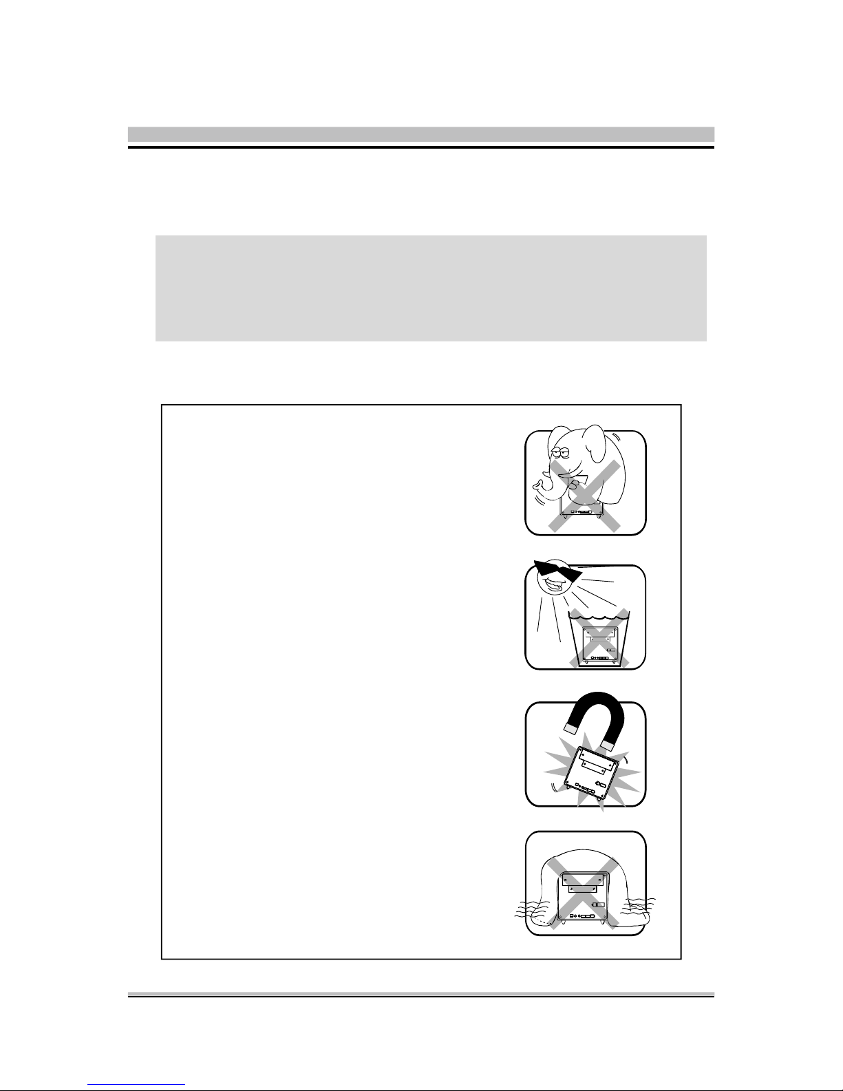
Installation Notices
Do not place this device underneath
heavy loads or in an unstable position.
Do not expose this device to high
levels of direct sunlight, high-humidity
or wet conditions.
Do not use or expose this device
around magnetic fields as magnetic
interference may affect the
performance of the device.
Do not block the air vents to this
device or impede the airflow in
any way.
CAUTION
Incorrectly replacing the battery may damage this computer. Replace only with
the same or equivalent as recommended by Shuttle. Dispose of used batteries
according to the manufacturer's instructions.
Safety Information
Read the following precautions before setting up a Shuttle XPC.
Page 6

TABLE OF CONTENTS
1 Function Introduction ............................................................................................. 1
1.1 XPC Introduction ............................................................................................. 1
1.2 Model Specifications ........................................................................................ 2
1.3 XPC Exterior Dissection .................................................................................... 3
1.3.1 XPC Front .............................................................................................. 3
1.3.2 XPC Back .............................................................................................. 4
1.4 Accessories ...................................................................................................... 5
1.5 XPC Mainboard................................................................................................ 6
1.5.1 SK21G mainboard illustration ................................................................. 6
1.5.2 Jumper Settings....................................................................................... 7
Fan Connectors (FAN1/FAN2) ................................................................ 7
Front Panel Connector (JP3/JP9) ............................................................. 8
Dual USB Header(JP4) ........................................................................... 8
SPDIF-Out Connector(JP8) ..................................................................... 8
LINE-IN (CN12)(Blue), CD-IN (CN11)(Black), mini CD-IN(CN14)(White)
Connectors............................................................................................ 9
Clear CMOS (JP1) ................................................................................ 10
Parallel Port Header-EXT. Printer Port (JP7) ............................................ 10
2 XPC Installation Guide .......................................................................................... 11
2.1 Installation ..................................................................................................... 11
2.1.1 Remove the Cover ............................................................................... 11
2.1.2 Remove the Rack ................................................................................. 12
2.2 CPU, DDR and ICE Installation ....................................................................... 13
2.2.1 Remove the ICE Module ....................................................................... 13
2.2.2 Install the CPU ..................................................................................... 15
2.2.3 Install the ICE Module ........................................................................... 17
2.3 DDR Installation............................................................................................. 19
2.4 Cable and Rack Installation ............................................................................ 20
Page 7

2.4.1 Installation the FDD Cable .................................................................... 20
2.4.2 Install the Serial Cable .......................................................................... 21
2.4.3 Installation Rack ................................................................................... 22
2.5 Peripheral Installation .................................................................................... 24
2.5.1 Installation the Serial ATA HDD ............................................................ 24
2.5.2 Installation the Floppy Driver ................................................................ 24
2.5.3 Installation an Optical Driver ................................................................ 25
2.6 Accessories Installation.................................................................................. 26
2.7 Final Touches ................................................................................................. 27
2.7.1 Close the Chassis Cover........................................................................ 27
2.7.2 Complete ............................................................................................. 28
2.8 XPC Accessories ............................................................................................. 28
2.9 Tech Support ................................................................................................. 28
2.A Technical Notes ............................................................................................. 29
2.A.1 Clear CMOS Button ............................................................................. 29
3 Driver and Software Installation ............................................................................ 30
3.1 Mainboard Driver CD .................................................................................... 30
3.1.1 Install Mainboard Software ................................................................... 31
Appendix ................................................................................................................. 32
Enter the BIOS ..................................................................................................... 32
THE MAIN MENU ................................................................................................ 33
Standard CMOS Features .............................................................................. 35
Advanced BIOS Features ............................................................................... 38
Advanced Chipset Features ........................................................................... 42
Integrated Peripherals .................................................................................... 47
Power Management Setup ............................................................................. 51
PnP/PCI Configurations ................................................................................ 55
Page 8

PC Health Status ........................................................................................... 57
Frequency Control ........................................................................................ 58
Load Fail-Safe Defaults .................................................................................. 59
Load Optimized Defaults............................................................................... 59
Set Supervisor/User Password ........................................................................ 59
Save & Exit Setup .......................................................................................... 60
Exit Without Saving ....................................................................................... 60
Page 9

1
English
< 1.1 XPC Introduction
The Shuttle XPC is the original high-performance Small Form Factor (SFF) computer.
Since the first model was introduced in 2001, the XPC has become the world’s bestselling SFF computer brand.
Each Shuttle XPC is sold as a ”barebone” computer~chassis, power supply and
motherboard. The user must add his own processor, memory, drives and, as applicable,
expansion cards. The XPC has been designed to be easily assembled and configured
directly by the end user. Consumers can choose to buy preconfigured, ready-to-run
XPC’s as well~a list of Shuttle-authorized value-added resellers can be found at www.
shuttle.com.
The Shuttle XPC owes its popularity to its unique combination of small-size, highperformance and near universal component compatibility. However, unlike ordinary
desktop computers, Shuttle XPC’s have been engineered as complete systems.
The XPC concept can be summarized as:
Use of high-performance, industry-standard components; Minimum size possible, while
preserving component compatibility and system expansion; Focus on quality~a commitment to quality construction, materials and industrial design.
To meet the above requirements, Shuttle has created and patented dozens of new
technologies, including the Integrated Cooling Engine (ICE), which extend and enhance the personal computing experience while reducing heat, noise and space
requirements.
Thank you for choosing the Shuttle XPC!
1 Function Introduction
Page 10

2
English
< 1.2 Model Specifications
Form Factor
Shuttle Small Form Factor
Processor
AMD Athlon 64 with 200MHz FSB clock on 754 - pin SMT Socket.
Chipset
VIA K8M800+VT8237R+
Memory
(2) 184 pins 333/400 DDR SDRAM DIMM
Supports Unbuffered/non-ECC DDR-SDRAM up to 2GB
Audio
VT1617A (6-CHANNEL)
Ethernet
VT6103
10/100 Mb/s LAN operation
IEEE 1394a
VIA VT6307, 1394 OHCI v1.0 compliant, Up to 400Mb/s data transfer rate
Serial ATA
VT8237R+ integrated SATA, Dual Channel UDMA 150MB/s S-ATA
Support RAID 0, 1
Onboard headers & connectors
(2) Fan connectors (1) Line_in header (1) AGP slot
(1) mini CD_in header (1) Power & reset header (1) PCI slot
(1) 2x5 pin USB 2.0 headers (1) Front Panel connector (2) Power connector
(1) Printer port header (1) IDE connector (2) SATA connectors
(1) Floppy connector (1) SPDIF-Out connector (1) CD-IN header
(1) Clear CMOS header
PSU
Output:200 Watt, Input: 100/240V AC, Active PFC, FCC, CE , BSMI, UL,
TUV, CCC, C-Tick, certificated
Chassis
G, Dimension: 300 (L) x 200 (W) x 185 (H)
Bay: (1) 3.5" bay (1) 3.5" bays ( internal) (1) 5.25" bay
Page 11
3
English
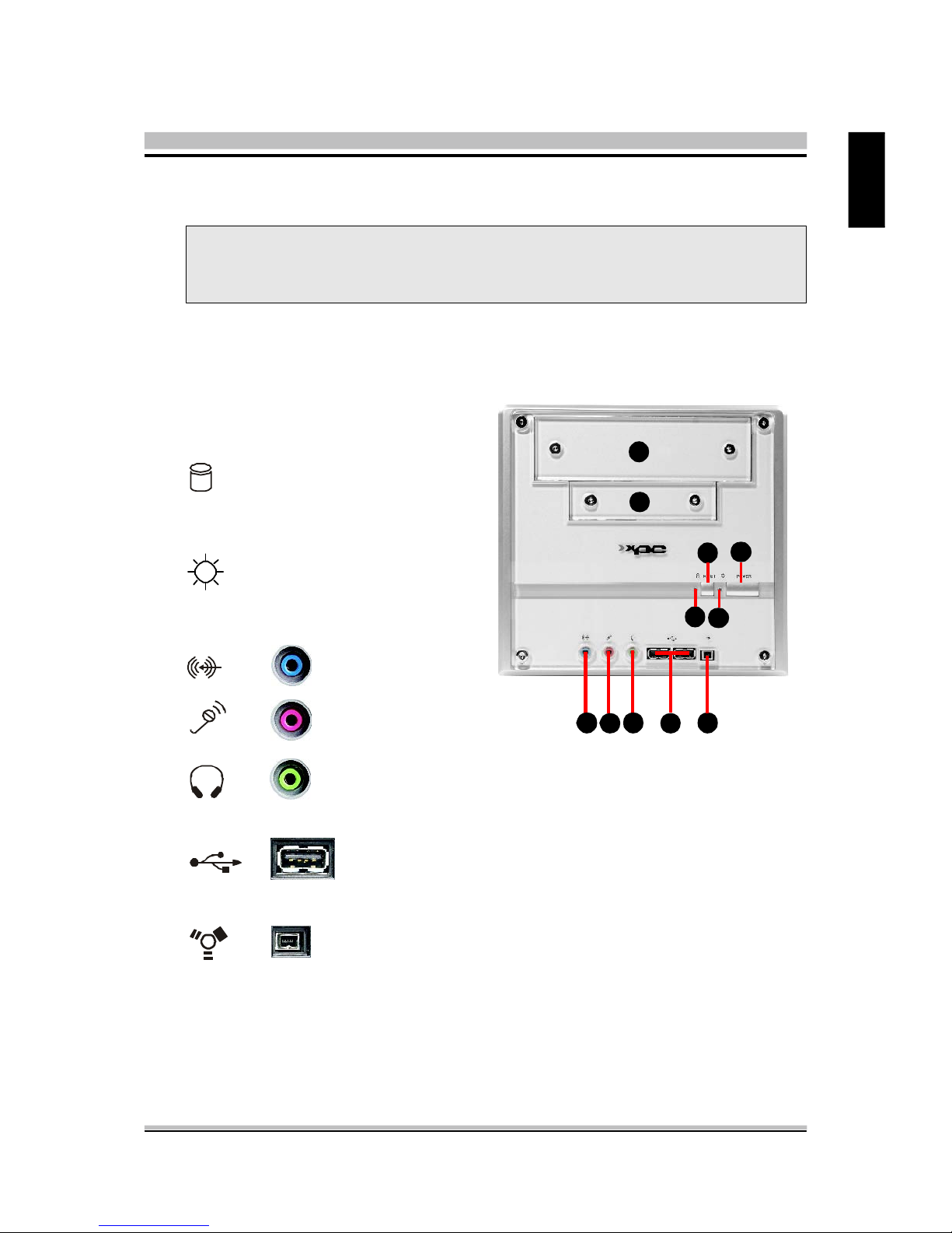
< 1.3.1 XPC Front
1. 5.25" Bay
2. 3.5" Bay
3. HDD LED
4. Reset
5. Power LED
6. Power
7. Line-in
8. Mic
9. Headphone
10. USB ports
11. FireWire® 400 mini port
< 1.3 XPC Exterior Dissection
Note : Shuttle offers a variety of different XPC models loaded with various
options. The illustration below will help familarize you with the included
features in your new XPC.
9
10 11
87
6
5
4
3
1
2
Page 12
4
English
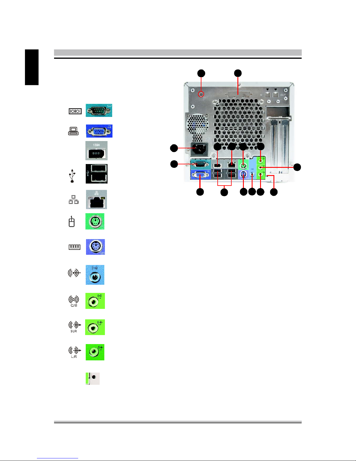
< 1.3.2 XPC Back
1. AC Power socket
2. COM port
3. VGA port
4. FireWire® 400 port
5. USB Ports
6. LAN port
7. PS/2 Mouse
8. PS/2 Keyboard
9. Line-In port
10. Central / Bass
11. Rear out(R/L)
12. Front out (R/L)
13. Clear CMOS button
1
2
3
4 657
11
10
12
9
8
1394
13
A B
A. Wireless LAN perforation
B. Parallel port perforation
Page 13
5
English
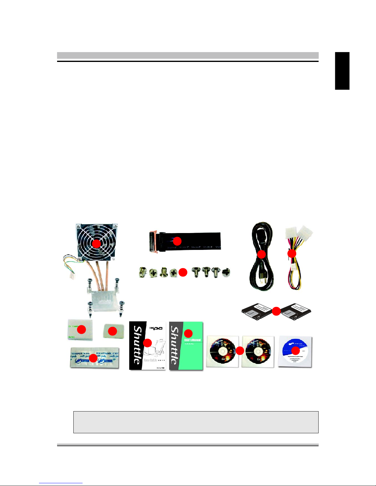
< 1.4 Accessories
1. ICE Heat-Pipe (1)
2. FDD cable (1)
3. Screws
4. Power Cord (1)
5. Power extension cable (1)
6. Adhesive (1)
7. Cable clip (1)
8. Heatsink compound (1)
9. XPC User Mnaual (1)
10. RAID manual (1)
11. Motherboard CD Driver(32bits/64bits) (2)
12. Shuttle Extras CD (1)
13. RAID Driver Floppy Disk (32bits/64bits) (2)
Note : Bundled Accessories may differ from specified. If there are items
missing, please contact your local authorized Shuttle dealer.
2
3
4
5
6
8
7
9
11 12
10
13
1
Page 14
6
English
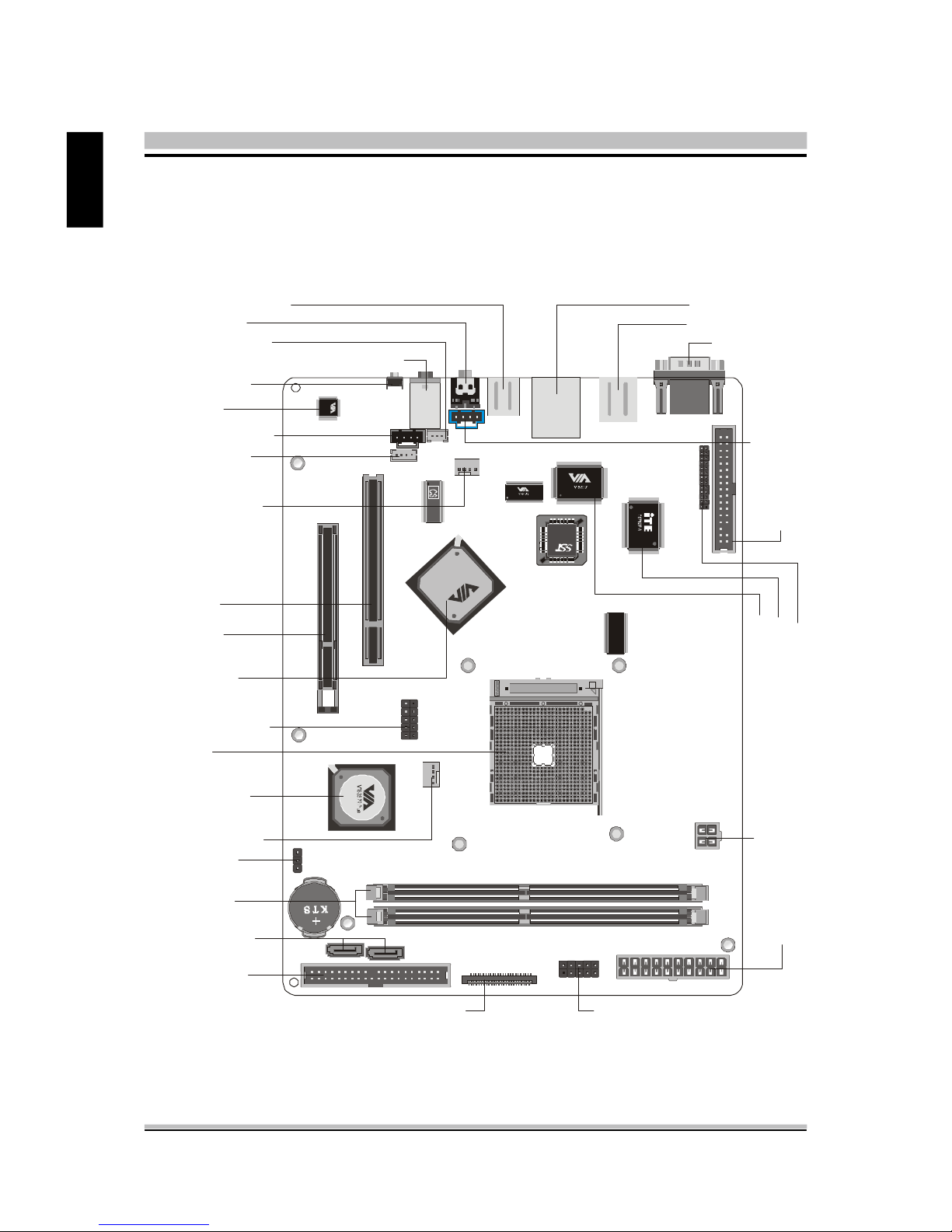
< 1.5 XPC Mainboard
< 1.5.1 SK21G mainboard illustration
SOCKET 754
K
8
M
8
0
0
VT1617A
0451CD TAIWAN
2HA3004049
ATX Power Connector- PWR1
Floppy Connector -FDC
1
One IDE Slot- IDE1
Front Panel Connector-JP9
Dual USB Header -JP4
Mini CD-IN-CN14
Clear CMOS-JP1
K8M800 Chipset
VT8237R+ Chipset
One AGP Slot
One PCI Slot
CD_IN Connector- CN11
LAN & Dual USB Port
Socket 754
Clear CMOS Button
VGA & COM Port
PS/2 K/B & M/S
Connector
Rear out/Front out/Center/Bass Audio Connectors
FAN Connector- FAN1
Front Panel Connector-JP3
E
XT. P
rin
t P
ort -JP
7
Two DIMM Slots
Serial
ATA- SATA1/
Dual Channel
SATA2
ATX Power Connector- CN13
ITE 8705F Chip
VT6307 Chip
Line_IN Header- CN12
1394 & Dual USB Port
FAN Connector- FAN2
VT1617A Chip
LINE-IN Connector
SPDIF-out Header-JP8
Page 15

7
English
< 1.5.2 Jumper Settings
Several hardware adjustments are made by setting jumpers on the mainboard. To
successfully change jumper settings, you will need to locate pin#1. In this manual,
pin#1 is represented by a white square, other pins are represented by a circles. An
illustration is shown below for your reference:
Caution!
1. Do not remove the mainboard from its case.
2. Do not touch the components on the mainboard. When installing components, pay special attention not to man handle sensative components
on the mainboard.
3. Wear an antistatic wrist strap or take other suitable measures to prevent
electrostatic discharge (ESD) whenever handling this equipment or installing components.
Jumpers with two pins are shown as for Closed [On] or for Open
[Off]. To Short jumper pins, simply place a plastic jumper cap over the desired pair
of pins.
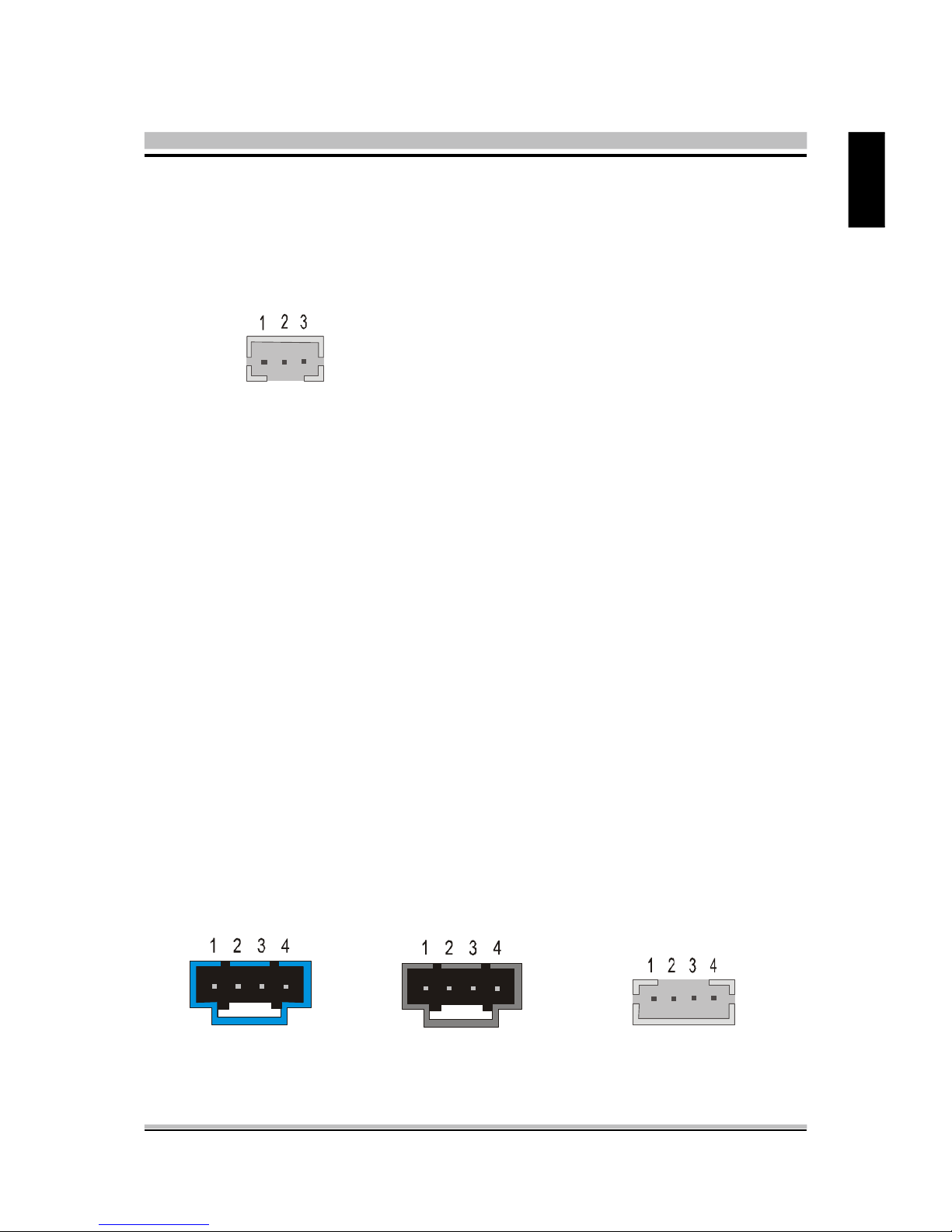
@ Fan Connectors (FAN1/FAN2)
The mainboard provides two onboard 12V
cooling fan power connectors to support
CPU (FAN1), System (FAN2) cooling fans.
Note : Both cable wiring and type of plug may vary depending on the fan
maker.
1
PWM_CTRL
SPEED_SENSE
+12V
GND
Page 16
8
English
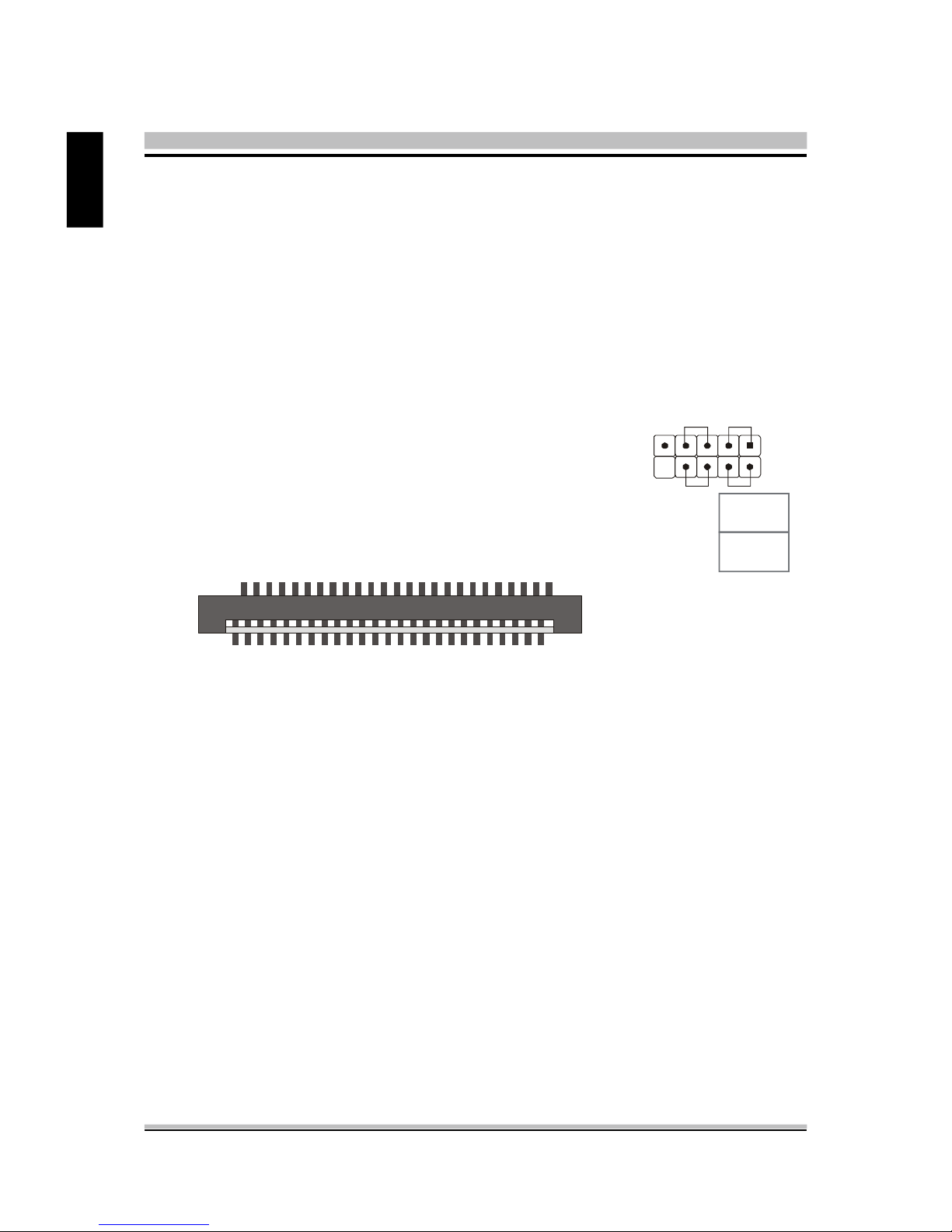
Pin Assignments (JP9):
1=HDLED_PU 2=GLEDA
3=HDLED 4=GLEDB
5=Reset_SW 6=Power_SW
7=GND 8=GND
9=NC 10=KEY
@ Front Panel Connector (JP3/JP9)
Header JP3can be used to provide operation status signals to the front daughterboard.
Note that this is an alternative header to the 50pins streamline header that also connects the motherboard to the front daughterboard.
Headers JP9 is used to connect cable to front panel connector mounted on front-panel
or back-panel. The front panel is where the hard drive activity lights, reset button, on/
off button, computer power on light, USB connectors, 1394 connectors, and audio
headers, are located.
2
JP 3
1
2
49
50
@ Dual USB Header (JP4)
The header is used to connect auxillary USB devices to the mainboard. The header is
directional and will only allow USB cables to be connected in one direction.
Pin Assignments (JP4):
1=VCC
3=Data05=Data0+
7=Ground
9=Key
2=VCC
4=Data16=Data1+
8=Ground
10=NC
1
-
+
RST
HLED
PWON
GLED
PWR LED
JP 9
-
+
-
+
Page 17
9
English
Pin Assignments (CN12): Pin Assignments (CN11): Pin Assignments (CN14):
1=Line-IN-Left 1=CD-IN-Left 1=Ground
2=Ground 2=Ground 2=CD-IN-Left
3=Ground 3=Ground 3=Ground
4=Line-IN-Right 4=CD-IN-Right 4=CD-IN-Right
@ LINE-IN (CN12)(Blue), CD-IN (CN11)(Black), mini CD-IN (CN14)
(White) Connectors
Port CN12(Blue), CN11(Black) and CN14(White) are used to connect stereo audio
inputs from a CD-ROM.
@ SPDIF-out Connector (JP8)
Port JP8 provides the mainboard connection for the SPDIF-out signal port.
Pin Assignments (JP8):
1=SPDIF-out signal
2=VCC
3=GND
JP 8
Page 18

10
English
@ Parallel Port Header-EXT. Printer Port (JP7)
A DB25 male parallel port header is located near the rear panel of the mainboard. The
header is used to connect a parallel port socket (PC8) to the mainboard. The parallel
printer port can be purchased from Shuttle as an optional accessory.
Pin Assignments (JP7):
1=PSTB 2=PD0 3=PD1
4=PD2 5=PD3 6=PD4
7=PD5 8=PD6 9=PD7
10=P_-ACK 11=P_BUSY 12=P_PE
13=P_SLCT 14=PAUTOFD 15=P_-ERR
16=PINIT 17=PSLCTIN 18=GND
19=GND 20=GND 21=GND
22=GND 23=GND 24=GND
25=GND 26=KEY
@ Clear CMOS Setting (JP1)
JP1 is used to clear CMOS data. Clearing CMOS will result in the permanently erasing
previous system configuration settings and the restoring original system settings.
1
1
Pin 1-2 (Default)
Pin 2-3 (Clear CMOS)
131211
10
9
8
7
6
5
4
3
2
1
26252423222120191817161514
Page 19

11
English
2 XPC Installation Guide
< 2.1 Installation
Note : For safety reasons, please ensure that the power cord is disconnected
before opening the case.
< 2.1.1 Remove the Cover
1. Unscrew the four thumbscrews.
2. Slide the cover backwards and upwards.
2
1
Page 20

12
English
< 2.1.2 Remove the Rack
1. Unbuckle the two Serial ATA HDD
mounting brackets from the rack.
2. Remove the rack.
1
2
3. Unscrew and remove the front bay covers.
Page 21

13
English
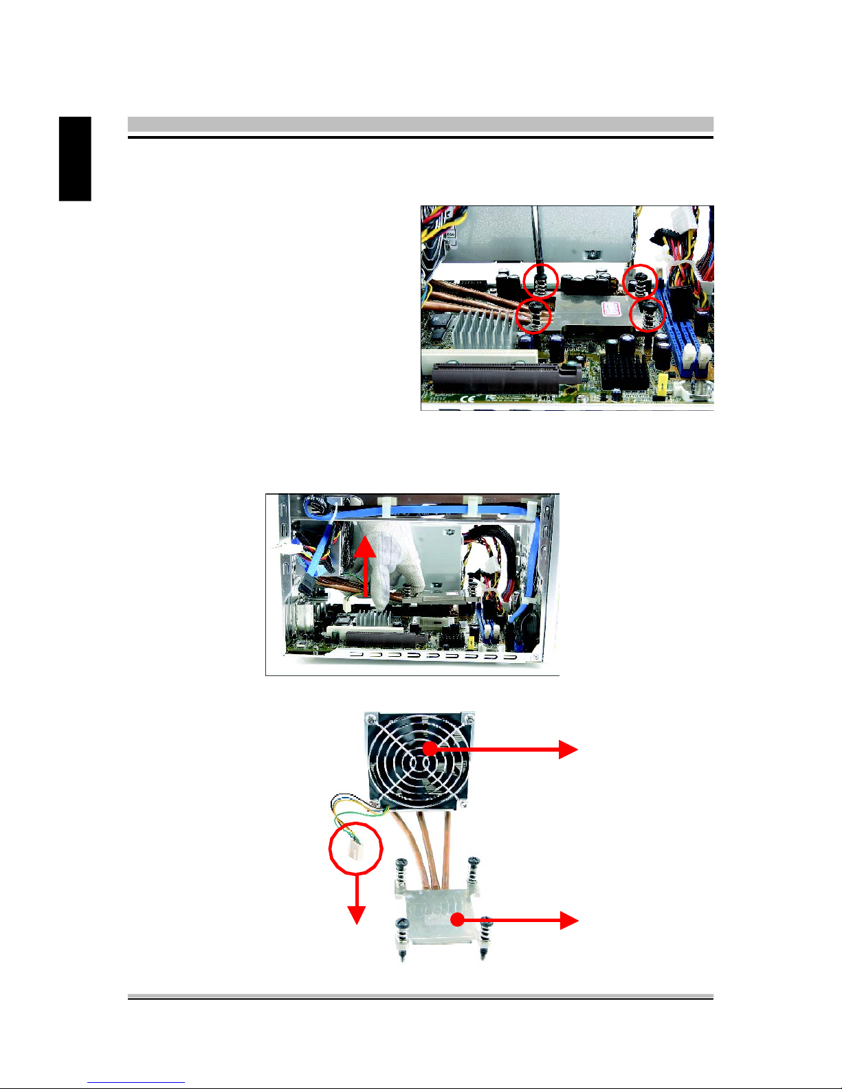
2. Unplug the fan power connector.
< 2.2 CPU, DDR and ICE Installation
< 2.2.1 Remove the ICE Module.
1. Unfasten the ICE fan thumbs screws on the back of the chassis.
Page 22
14
English
4. Remove the ICE module from the chassis and put it aside.
3. Unfasten the four ICE module attachment screws.
ICE Heat-Pipe Module
Heat-pipe
Smart Fan
Smart Fan Power Connector
Page 23

15
English
< 2.2.2 Install the CPU
1. Pull up the CPU socket lever to 90-degrees.
Push the lever
CPU socket lever at 90 degrees
2. Match the yellow triangle on a corner of the CPU with the triangle on the socket corner
and gently insert the CPU into the socket.
Lever
Triangle Mark
AMD AthlonTM 64
Processor
Lever
2
1
Page 24

16
English
3. Press down the CPU socket lever.
4. Spread an even layer of thermal compound on the CPU die.
Note : Failure to correctly align the CPU and socket can result in damage to
the CPU.
Thermal compound application area
Page 25

17
English
< 2.2 .3 Install the ICE Module
1. Place the ICE module on the CPU and match the screws with the holes on the
motherboard.
2. Screw the ICE module to the motherboard. Press down firmly on the opposite corner
as you screw.
3. Connect the fan's power connector.
Page 26

18
English
4. Fasten the smart fan to the chassis with the four thumbscrews.
Page 27

19
English
<2.3 DDR Installation
Install the DDR module in DIMM1/DIMM2.
1. Unlock the DIMM latch.
2. Align the DDR module's cutout with the DIMM slot notch.
3. Check that the latches are closed, and the DDR module is firmly installed.
Notch
Cutout
Latch
Latch
Page 28

20
English
<2.4 Cable and Rack Installation
<2.4.1 Install the FDD Cable
1. Plug the FDD cable in the FDD header (FDD1).
2. Fold the FDD cable under the power supply.
Pin 1
(white line)
Pin1
FDD1
Pin1(white line)
3. Fix the FDD cable to the power and chassis rail with the suppied adhesive tape.
Page 29

21
English
< 2.4.2 Install the Serial ATA HDD Cable
1. Plug the Serial ATA cable to the SATA1 header.
2. Loosen the purse lock and separate the Serial ATA HDD and FDD power connectors.
SATA header
Purse lock
Serial ATA Power connector
Page 30

22
English
< 2.4.3 Install the Rack
1. Place the HDD in the rack and secure with screws from the side.
2. Place the FDD in the rack and tighten with its own screws.
Note : The second screw is located at the opposite side of rack.
Page 31

23
English
3. Place the rack in the chassis.
4. Refasten the rack.
Page 32

24
English
<2.5 Peripheral Installation
< 2.5.1 Install the Serial ATA HDD
1. Connect the Serial ATA cable and power connector he HDD.
< 2.5.2 Install Floppy Drive
1. Connect the FDD cable and power connector into the Floppy drive.
Serial ATA Power connector
Serial ATA HDD cable
FDD connector
Power connector
Page 33

25
English
Optical drive cable
Optical drive Power cable
Screws (Optical Drive)
< 2.5.3 Install an Optical Drive
1. Slide optical driver into the chassis.
2.Check the optical drive front alignment and fasten the four side screws.
3.Plug the optical driver and power cable into the optical drive.
Page 34

26
English
<2.6 Accessories Installation
< 2.6.1 Install PCI/AGP Card
1. An AGP card will be used to demonstrate the installation procedure.
Lift Up
Bracket
3. Install AGP Card into AGP slot and secure the bracket.
AGP Card
AGP Door
2.Unfasten expansion slot bracket screws and remove the aluminum back panel breket.
Put the back panel bracket aside.
Page 35

27
English
< 2.7 Final Touches
< 2.7.1 Close the Chassis Cover
1. Replace the cover and refasten the thumbscrews.
2
1
Page 36

28
English
< 2 .7 .2 Compl et e
< 2 .9 Tech Support
1. Shuttle Inc.
http://www.shuttle.com
2. Tech Support
http://global.shuttle.com/Support/Support.asp
3. Download
http://global.shuttle.com/Download/Download.asp
4. Barebone FAQ
http://global.shuttle.com/Support/SupportFAQ_Brb.asp
5. Barebone Support List
http://global.shuttle.com/Support/SupportList_Brb.asp
< 2 .8 XPC Accessories
Shuttle offers over 25 great upgrade and modding kits for your XPC. Visit our website at
http://www.shuttle.com for more information or speak to your local retailer.
Page 37

29
English
< 2.A Technical Notes
< 2.A.1 Clear CMOS Button
This XPC comes enhanced with an easy-to-use Clear CMOS Button. This button allows
users to reset BIOS information to factory default settings.
1. Power down the XPC and remove the power cord.
2. Press the Clear CMOS Button by inserting a pointed object (e.g. a pen nib) into the clear
CMOS hole. Keep it pressed for 5 seconds.
3. Reconnect the power cord and turn on the computer.
Note : Remove the power cord before clearing CMOS.
Clear CMOS button
Page 38

30
English
< 3.1 Mainboard Driver CD
The Mainboard Driver CD contains all the motherboard driver necessary to optimize
the performance of this XPC in a Windows(R) OS. Install these drivers after installing
Microsoft(R) Windows(R).
Navigation Bar Description :
F Install Mainboard Software - VIA 4in1 Driver, VIA VGA Driver, VIA LAN
Driver,VIA Audio Driver, VIA RAID Driver,VIA USB 2.0 Driver.
F Install Utility - Install Acrobat Reader, WinFlash Utility.
F Manual - SK21G user's guide and RAID manual in PDF format.
F Link to Shuttle Homepage - Link to shuttle website homepage.
F Browse this CD - Allows you to see contents of this CD.
F Quit - Close this CD.
Note : The CD contents attached in SK21G mainboard are subject to
change without notice.
3 Driver and Software Installation
Page 39

31
English
< 3.1.1 Install Mainboard Software
Insert the attached CD into your CD-ROM drive. The CD AutoRun screen should
appear. If the AutoRun screen does not appear, double click on Autorun icon in My
Computer to bring up Shuttle Mainb-oard Software Setup screen.
Click the “Install Main-board Software“ bar. Individually install the following drivers.
F Install VIA 4in1 Driver
F Install VIA VGA Driver
F Install VIA LAN Driver
F Install VIA Audio Driver
F Install VIA RAID Driver
F Install VIA USB 2.0 Driver
Page 40

32
English
BIOS Settings
The SK21G BIOS ROM has a built-in Setup program that allows users to modify basic
system configuration. This information is stored in battery-backed RAM so that it retains Setup information even if the system power is turned off.
The system BIOS manages and executes a variety of hardware related functions
including:
System date and time
Hardware execution sequence
Power management functions
Allocation of system resources
Enter the BIOS
To enter the BIOS (Basic Input / Output System) utility, follow these steps:
Step1. Power on the computer. The system will perform its POST (Power-On
Self Test) routine checks.
Step2. Press the <Del> key immediately, or at the following message:
Press DEL to enter SETUP, or simultaneously press <Ctrl>,<Alt>,
<Esc> keys
Note 1. If you miss the train of words mentioned in step2 (the message disap-
pears before you can respond) and you still wish to enter BIOS Setup,
restart the system and try again by turning the computer OFF and
ON again or by pressing the <RESET> switch located at the
computer’s front-panel. You may also reboot by simultaneously
pressing the <Ctrl>,<Alt>, <Del> keys simultaneously.
Note 2. If you do not press the keys in time and system does not boot, the
screen will prompt an error message, and you will be given the
following options:
"Press F1 to Continue, DEL to Enter Setup”
Step3. When you enter the BIOS program, the CMOS Setup Utility will display the
Main Menu, as shown in the next section.
Appendix
Page 41

33
English
The Main Menu
Once you enter the AwardBIOS(tm) CMOS Setup Utility, the Main Menu
will appear on the screen. The Main Menu allows you to select from several setup functions and two exit choices. Use the arrow keys to select
among the items and press <Enter> to accept and enter the sub-menu.
Note that a brief description of each highlighted selection appears at the
bottom of the screen.
Setup Items
The main menu includes the following main setup categories. Recall that
some systems may not include all entries.
Standard CMOS Features
Use this menu for basic system configuration.
Advanced BIOS Features
Use this menu to set the Advanced Features available on your system.
Advanced Chipset Features
Use this menu to change the values in the chipset registers and optimize
your system's performance.
Integrated Peripherals
Use this menu to specify your settings for integrated peripherals.
Power Management Setup
Use this menu to specify your power management settings.
PnP / PCI Configurations
This entry appears if your system supports PnP / PCI.
Page 42

34
English
PC Health Status
This entry displays the current system temperature, Voltage, and FAN
settings.
Frequency Control
Use this menu to specify your settings for ratio control.
Load Fail-Safe Defaults
Use this menu to load the BIOS default values for the minimal/stable performance of your system to operate.
Load Optimized Defaults
Use this menu to load the BIOS default values that are factory-set for optimal system operation. While Award has designed the custom BIOS to
maximize performance, the factory has the right to change these defaults
to meet users' needs.
Set Supervisor / User Password
Use this menu to change, set, or disable password protection. This allows
you to limit access to the system and Setup, or only to Setup.
Save & Exit Setup
Save CMOS value changes in CMOS and exit from setup.
Exit Without Saving
Abandon all CMOS value changes and exit from setup.
Page 43

35
English
@ Standard CMOS Features
The items in the Standard CMOS Setup Menu are divided into several
categories. Each category includes none, one or more than one setup
items. Use the arrow keys to highlight the item and then use the <PgUp>
or <PgDn> keys to select the value you want in each item.
Date
<Month> <DD> <YYYY>
Set the system date. Note that the 'Day' automatically changes when
you set the date.
Time
<HH : MM : SS>
The time is converted based on the 24-hour military-time clock.
For example, 5 p.m. is 17:00:00.
IDE Channel 0 Master/Slave
Options are in its sub-menu.
Press <Enter> to enter the sub-menu of detailed options.
Drive A
Select the type of floppy disk drive installed in your system.
Ø The choice: None, 360K, 5.25 in, 1.2M, 5.25 in, 720K, 3.5 in,
1.44M, 3.5 in, or 2.88M, 3.5 in.
Video
Select the default video device.
Ø The choice: EGA/VGA, CGA 40, CGA 80, or MONO.
Page 44

36
English
Halt On
Select the situation in which you want the BIOS to stop the POST
process and notify you.
Ø The choice: All Errors, No Errors, All, But Keyboard, All, But
Diskette, or All, But Disk/Key.
Base/Extended/Total Memory
Theseitems are automatically detected by the system at start up time.
These are display-only fields. You can't make change to these fields.
******************************************************
IDE Adapters
The IDE adapters control the hard disk drive. Use a separate sub-menu
to configure each hard disk drive.
IDE HDD Auto-Detection
Press <Enter> to auto-detect HDD on this channel. If detection is
successful, it fills the remaining fields on this menu.
Ø Press Enter
IDE Channel 0 Master
Selecting 'manual' lets you set the remaining fields on this screen and
select the type of fixed disk. "User Type" will let you select the number of
cylinders, heads, etc., Note: PRECOMP=65535 means
NONE !
Ø The choice: None, Auto, or Manual.
Access Mode
Choose the access mode for this hard disk.
Ø The choice: CHS, LBA, Large, or Auto.
Capacity
Disk drive capacity (Approximated). Note that this size is usually slightly
greater than the size of a formatted disk given by a disk checking program.
Ø Auto-Display your disk drive size.
The following options are selectable only if the 'IDE Primary Master'
item is set to 'Manual'
Page 45

37
English
Cylinder
Set the number of cylinders for this hard disk.
Ø Min = 0, Max = 65535
Head
Set the number of read/write heads.
Ø Min = 0, Max = 255
Precomp
Warning: Setting a value of 65535 means no hard disk.
Ø Min = 0, Max = 65535
Landing zone
Set the Landing zone size.
Ø Min = 0, Max = 65535
Sector
Number of sector per track.
Ø Min = 0, Max = 255
******************************************************
Page 46

38
English
@ Advanced BIOS Features
This section allows you to configure your system for basic operation. You
have the opportunity to select the system's default speed, boot-up sequence,
keyboard operation, shadowing, and security.
Hard Disk Boot Priority
This item allows you to select Hard Disk Book Device Priority.
BIOS Write Protect
The item allows you to enable/disable the Bios Write Protect.
Ø The choice: Enabled or Disabled.
Virus Warning
Allows you to choose the VIRUS Warning feature for IDE Hard Disk boot
sector protection. If this function is enables and someone attempts to write
data into this area, BIOS will show a warning message on screen, and an
alarm beep.
Enabled Activates automatically when the system boots up, causing
a warning message to appear when anything attempts to access the boot sector or hard disk partition table.
Disabled No warning message will appear when anything attempts
to access the boot sector or hard disk partition table.
Ø The choice: Enabled or Disabled.
Page 47

39
English
CPU Internal Cache
All processors that can be installed in this mainboard use internal level 1
(L1) cache memory to improve performance. Leave this item at the default value for better performance.
Ø The choice: Enabled or Disabled.
External Cache
Most processors that can be installed in this system use external level 2
(L2) cache memory to improve performance. Leave this item at the default value for better performance.
Ø The choice: Enabled or Disabled.
CPU L2 Cache ECC Checking
This item to enabled or disabled ECC (Error Correction Code) error
checking on the CPU cache memory.
Ø The choice: Enabled or Disabled.
Quick Power On Self Test
This item speeds up Power-On Self Test (POST) after you power on the
computer. If it is set to enabled, BIOS will shorten or skip some check
items during POST.
Ø The choice: Enabled or Disabled.
USB Flash Disk Type
This item allows you to select USB Flash Disk Type.
Ø The choice: Auto, Floppy or HDD.
First/Second/Third Boot Device
The BIOS attempts to load the operating system from the devices in the
sequence selected in these items.
Ø The Choice: Floppy, LS120, Hard Disk, CDROM, ZIP100, USB-FDD,
USB-ZIP, USB-CDROM, LAN, or Disabled.
Boot Other Device
Select Your Boot Device Priority.
Ø The choice: Enabled or Disabled.
Page 48

40
English
Boot Up Floppy Seek
Seeks disk drives during boot-Up. Disabling speed boots up. Enabled tests
floppy drives to determine whether they have 40 or 80 tracks.
Ø The choice: Enabled or Disabled.
Boot Up NumLock Status
Selects power on state for NumLock.
Ø The choice: Off or On.
Typematic Rate Setting
Keystrokes repeat at a rate determined by the keyboard controller.
When this controller enabled, the typematic rate and typematic delay
can be selected.
Ø The choice: Enabled or Disabled.
Typematic Rate (Chars/Sec)
This item sets how many times the keystroke will be repented in a second
when you hold the key down.
Ø The choice: 6, 8, 10, 12, 15, 20, 24 or 30.
Typematic Delay (Msec)
Sets the delay time after the key is held down before it begins to repeat the
keystroke.
Ø The choice: 250, 500, 750 or 1000.
Security Option
Select whether the password is required every time the system boots or
only when you enter setup.
System The system will not boot and access to Setup will be
denied if the correct password is not entered promptly.
Setup The system will boot, but access to Setup will be
denied if the correct password is not entered promptly.
Ø The choice: System or Setup.
Note : To disabled security, select PASSWORD SETTING at Main Menu,
and then you will be asked to enter password. Do not type anything and just press <Enter>; it will disable security.
Once the security is disabled, the system will boot, and you can
enter Setup freely.
Page 49

41
English
HDD Security Freeze Lock
Selects enable/disable HDD Security Freeze Lock, Enabled - prevents any
external application from locking Hard drive except for BIOS.
Ø The choice: Enabled or Disabled.
APIC Mode
Selects enable/disable IO APIC function
Ø The choice: Enabled or Disabled.
MPS Version Control For OS
Selects the operating system multiprocessor support version.
Ø The choice: 1.1 or 1.4
Video BIOS Shadow
Determines whether video BIOS will be copied to RAM. However, it is
optional depending on chipset design. Video Shadow will increase the
video speed.
Ø The choice: Enabled or Disabled.
Page 50

42
English
@ Advanced Chipset Features
This section allows you to configure the system based on the specific
features of the installed chipset. This chipset manages bus speeds and access
to system memory resources, such as DRAM and the external cache. It also
coordinates communications between the conventional ISA bus and the PCI
bus. It states that these items should never need to be altered.
The default settings have been chosen because they provide the best
operating conditions for your system. If you discovered that data was being
lost while using your system, you might consider making any changes.
AGP & P2P Bridge Control
Options are in its sub-menu.
Press <Enter> to enter the sub-menu of detailed options.
AGP Aperture Size
Select the size of Accelerated Graphics Port (AGP) aperture. The aperture is a portion of the PCI memory address range dedicated to graphics
memory address space. Host cycles that hit the aperture range are
forwarded to the AGP without any translation.
Ø The Choice: 32M, 64M, 128M, 256M, 512M or 1G.
AGP 2.0 Mode
This item allows you to select the AGP Mode. If you set Onboard VGA
or AGP 3.0 Mode AGP Card, the default value is 8X.
Ø The Choice: 1x, 2x or 4x.
Page 51

43
English
AGP Driving Control
This item enables the system to automatically select its output buffer
drive strength or make it manually selectable by an end user.
Ø The Choice: Auto or Manual.
AGP Driving Value
This item enables an end user to manually select the AGP output buffer
drive strength.
Ø Key in a HEX number: Min=0000, Max=00FF.
AGP Fast Write
This item enables an end user to manually select the AGP output buffer
drive strength.
Ø The Choice: Enabled or Disabled.
AGP Master 1 WS Write
When this item enabled, writing to the AGP(Accelerated Graphics Port)
is executed with one wait state.
Ø The Choice: Enabled or Disabled.
AGP Master 1 WS Read
When this item enabled, reading from the AGP (Accelerated Graphics
Port) is executed with one wait state.
Ø The Choice: Enabled or Disabled.
AGP 3.0 Calibration Cycle
If you set Onboard VGA or AGP 3.0 Mode AGP Card, the item is
enable/disable the AGP calibration cycle.
Ø he Choice: Enabled or Disabled.
VGA Share Memory Size
This item defines the onboard VGA shared memory size.
Ø The Choice: Disabled, 16M, 32M or 64M.
DRAM Configuration
Options are in its sub-menu.
Press <Enter> to enter the sub-menu of detailed options.
Current FSB Frequency
This item shows the current CPU Front Side Bus Speed.
Current DRAM Frequency
This item shows the current DRAM speed.
Page 52

44
English
DDR Timing Setting
This item allows you to set DRAM timing.
Ø The Choice: Auto or Manual.
Memclock index valux (Whz)
Places an artificial memory clock limit on the system.
Memory is prevented from running faster than this frequency.
Ø The Choice: 100, 133,166 or 200.
CAS# latency (Tc1)
This item defines the timing delay in clock cycles before SDRAM starts
a read command after receiving it.
Ø The Choice: 2, 2.5 or 3.0.
Min RAS# active time (tRAS)
This precharge time is the number of cycles it takes for DRAM to accumulate its charge before refresh.
Ø The Choice: Auto or 5 ~15 Bus Clocks.
RAS# to CAS# delay (tRCD)
This item defines the timing of the transition from RAS (row address
strobe) to CAS (column address strobe) as both rows and columns are
separately addressed shortly after DRAM is refreshed.
Ø The Choice: Auto or 2 ~7 Bus Clocks.
Row Precharge Time (tRP)
This item defines the numbers of cycles for RAS (row address strobe) to
be allowed to precharge.
Ø The Choice: Auto or 2 ~7 Bus Clocks.
MTRR mapping mode
This item allows you to set the MTRR mapping mode.
Ø The Choice: Continuous or Discrete.
Page 53

45
English
LDT & PCI Bus Control
Options are in its sub-menu.
Press <Enter> to enter the sub-menu of detailed options.
Upstream LDT Bus Width
This item allows you to select the LDT upstream width.
Ø The Choice: 8 bit or 16 bit.
Downstream LDT Bus Width
This item allows you to select the LDT downstream width.
Ø The Choice: 8 bit or 16 bit.
LDT Bus Frequency
The item selects the LDT bus frequency.
Ø The Choice: Atuo, 200 MHz, 400 MHz, 600 MHz or 800 MHz.
PCI1 Master 0 WS Write
When this item enabled, writing to the PCI bus is executed with zero
wait state.
Ø The Choice: Enabled or Disabled.
PCI2 Master 0 WS Write
When this item enabled, writing to the AGP bus is executed with zero
wait state.
Ø The Choice: Enabled or Disabled.
PCI1 Post Write
This Item enable/disable AGP post write function, which means when
cpu accessing the AGP data, the chipset can queue the instruction when
the AGP bus is busy, then write the data when AGP bus is available .
Ø The Choice: Enabled or Disabled.
PCI2 Post Write
This Item enable/disable PCI post write function, which means when cpu
accessing the PCI data, the chipset can queue the instruction when the
PCI bus is busy, then write the data when AGP bus is available.
Ø The Choice: Enabled or Disabled.
Page 54

46
English
PCI Delay Transaction
The chipset has an embedded 32-bit posted write buffer to support
delay transactions cycles. Select Enabled to support compliance with
PCI specification version 2.1.
Ø The Choice: Enabled or Disabled.
Memory Hole
You can reserve this area of system memory for ISA adapter ROM.
When this area is reserved, it can't be cached. The user information of
peripherals that need to use this area of system memory ususlly discusses their memory requirements.
Ø The Choice: Disabled or 15M-16M.
VLINK Data Rate
This item allows you to set VLINK Data Rate.
Ø The Choice: 8x or 4x.
Init Display First
This item allows you to decide to activate whether PCI slot or AGP first.
Ø The choice: PCI Slot or AGP/Onboard.
System BIOS Cacheable
Selecting Enabled allows caching of the system BIOS ROM at F0000hFFFFFh, resulting in better system performance. However, if any program is written to this memory area, a system error may result.
Ø The choice: Enabled or Disabled.
Page 55

47
English
@ Integrated Peripherals
VIA OnChip IDE Device
Option are in its sub-menu.
Press<Enter>to enter the sub-menu of detailed options.
OnChip SATA
The chipset contains a SATA interface with support to on SATA
channel. Select Enabled to active the primary SATA interface. Select
Disabled to deactivate the primary interface.
Ø The choice: Disabled or Enabled.
Parallel ATA
Serial ATA
Master
Slave
IDE1
Disable
Serial ATA 1
(Channel 0)
Serial ATA 2
Page 56

48
English
SATA Mode
You can select SATA Mode as "RAID" to run RAID bios and make raid.
Ø The choice: IDE or RAID.
OnChip IDE Channel0
The chipset contains a PCI IDE interface with support to two IDE channels.
Select Enabled to activate the primary IDE interface; select Disabled to deactivate this interface.
Ø The choice: Enabled or Disabled.
IDE Prefetch Mode
The onboard IDE drive interfaces support IDE prefetching for faster drive
access. If you install a primary and/or secondary add-on IDE interface, set
this field to Disabled if the interface does not support prefetching.
Ø The choice: Enabled or Disabled.
Primary Master/Primary Slave/Secondary Master/Secondary
Slave PIO
Each IDE channel supports a master device and a slave device. These
four items let you assign which kind of PIO ( Programmed Input / Output
) is used by IDE devices. Choose Auto to let the system auto detect which
PIO mode is best or select a PIO mode from 0-4.
Ø The choice: Auto, Mode 0, Mode 1, Mode 2, Mode 3 or Mode 4.
Primary Master/Primary Slave/Secondary Master/Secondary
Slave UDMA
Each IDE channel supports a master device and a slave device.
This mainboard supports UltraDMA technology, which provides faster
access to IDE devices.
Ø The choice: Auto or Disabled.
IDE HDD Block Mode
If your IDE hard disk drive supports block mode (most new drives do),
select Enabled to automatic detect the optimal number of block read
and writes per sector that the drive can support and improves the
speed of access to IDE devices.
Ø The choice: Enabled or Disabled.
VIA Onchip PCI Device
Option are in its sub-menu.
Press<Enter>to enter the sub-menu of detailed options.
Page 57

49
English
Onboard Audio
This item allows you to select audio chip to support Audio. Disable this
item. If you are going to install a PCI audio add-on card.
Ø The Choice: Auto or Disabled.
Onboard LAN
This item allows you to select onchip LAN.
Ø The Choice: Enabled or Disabled.
Onboard Lan Boot ROM
Device whether to invoke the boot ROM of the onboard LAN chip.
Ø The Choice: Enabled or Disabled.
Onchip USB Controller
Select Enabled if your system contains a Universal Serial Bus (USB) port
on this mainboard.
Ø The Choice: All Disabled, All Enabled, 1&2 USB Port, 2&3 USB
Port, 1&3 USB Port or 1~3 USB.
Onchip EHCI Controller
Select Enabled if your system contains a Universal Serial Bus USB2.0
port on this mainboard.
Ø The choice: Enabled or Disabled.
SuperIO Device
Option are in its sub-menu.
Press<Enter>to enter the sub-menu of detailed options.
Onboard FDC Controller
This item specifices onboard floppy disk drive controller. This setting
allows you to connect your floppy disk drives to the onboard floppy
connector.
Ø The choice: Enabled or Disabled.
Onboard Serial Port
This option is used to assign the I/O address and interrupt request ( IRQ)
for the onboard serial port1 ( COM1 ).
Ø The choice: Disabled, 3F8/IRQ4, 2F8/IRQ3, 3E8/IRQ4, 2E8/IRQ3,
or Auto.
Onboard Parallel Port
This item allows you to determine onboard parallel port controller I/O
address and interrupt request ( IRQ ).
Ø The choice: 378/IRQ7, 278/IRQ5, 3BC/IRQ7 or Disabled.
Page 58

50
English
Parallel Port Mode
Select an operating mode for the onboard parallel (printer) port. Select
Normal, Compatible, or SPP unless you are certain your hardware and
software both support one of the other available modes.
Ø The choice: SPP, EPP, ECP or ECP+EPP.
ECP Mode Use DMA
When the onboard parallel is set to ECP mode, the parallel port can use
DMA3 or DMA1.
Ø The choice: 1 or 3.
Page 59

51
English
@ Power Management Setup
The Power Management Setup allows you to configure your system to
most effectively saving energy while operating in a manner consistent
with your own style of computer use.
ACPI Function
This item allows you to enable/disable the Advanced Configuration and
Power Management (ACPI).
Ø Always "Enabled".
ACPI Suspend Type
This item allows you to select sleep state when suspend.
Ø The choice: S1(POS) or S3(STR).
HDD Power Down
The IDE hard drive will spin down if it is not accessed within a specified
length of time. Options are from 1 Min to 15 Min and Disable.
Ø The choice: Disabled or 1 Min ~ 15 Min.
Suspend Mode
When this item enabled and after the set up time of system inactivity, all
devices except the CPU will be shut off.
Ø The choice: Disable, 1Min, 2Min, 4Min, 6Min, 8Min, 10Min,
20Min, 30Min, 40Min or 1Hour.
Video Off Option
This item specifies on/off for the monitor when it enters the power-
Page 60

52
English
saving mode.
Ø The choice: Suspend->off or Always On.
Video Off Method
This determines the manner in which the monitor is blanked.
Blank Screen This option only writes blanks to the video buffer.
V/H SYNC+Blank This selection will cause the system to turn off
the vertical and horizontal synchronization
ports and write blanks to the video buffer.
DPMS Supported Initial display power management signaling.
Ø The choice: V/H SYNC+Blank, Blank Screen or DPMS Supported.
MODEM Use IRQ
This determines the IRQ which the MODEM can use.
Ø The choice: 3, 4, 5, 7, 9, 10, 11 or NA.
Soft-Off by PWR-BTN
Under ACPI you can create a software power down. In a software
power down, the system can be resumed by Wake UP Alarms. This
item lets you install a software power down that is controlled by the
power button on your system. If the item is set to Instant-Off, then the
power button causes a software power down. If the item is set to Delay
4 Sec. then you have to hold the power button down for 4 seconds to
cause a software power down.
Ø The choice: Instant-Off or Delay 4 Sec.
Run VGABIOS if S3 Resume
This item becomes available when the previous item is seto to S3(STR)
or S1 & S3. The item allows the system to initialize a VGA BIOS from S3
(Suspend to RAM) sleep state.
Ø The choice: Yes, No or Auto.
PWRON After PWR-Fail
This item select power on function when power fail.
Ø The choice: Off, On or Former-Sts.
IRQ / Event Activity Detect
Option are in its sub-menu.
Press<Enter>to enter the sub-menu of detailed options.
PS2KB Wakeup Select
Select a hotkey or password to wake up the system.
Ø The choice: Hot key or Password.
Page 61

53
English
PS2KB Wakeup from S3/S4/S5
Set a key to awaken the system from a keyboard.
Ø The choice: Disable, Ctrl+F1~Ctrl+F12, Power, Wake or Any
Key.
PS2MS Wakeup from S3/S4/S5
This item enables or disables the PS/2 mouse to awaken the system.
Ø The choice: Disabled or Enabled.
USB Resume from S3
When this item is enabled, any activity from the USB device will
awaken the system from S3 mode.
Ø The choice: Disabled or Enabled.
VGA
Select ON to have the VGA awaken the system.
Ø The choice: OFF or ON.
LPT & COM
This item determines if any activity from LPT, COM, or both wakes up
the system.
Ø The choice: NONE, LPT, COM or LPT/COM.
HDD & FDD
Select ON to have any activity from HDD or FDD wake up the system.
Ø The choice: OFF or ON.
PCI Master
Select ON to have any activity from the primary PCI wake up the
system.
Ø The choice: OFF or ON.
PowerOn by PCI Card
This item enables/disables the power on function of PCI card.
Ø The choice: Disabled or Enabled.
Modem Ring Resume
When this item is enabled, any event from Modem Ring will awaken
the system which has been powered down.
Ø The choice: Disabled or Enabled.
RTC Alarm Resume
When this item is enabled, your can set the date and time at which the
RTC (real-time clock) alarm awakens the system from suspend mode.
Ø The choice: Disabled or Enabled.
Page 62

54
English
Data (of Month)
This item selects the alarm date.
Ø Key in a DEC number: Min=0, Max=31.
Resume Time (hh:mm:ss)
This item selects the alarm Time.
[hh] Ø Key in a DEC number: Min=0, Max=23.
[mm] Ø Key in a DEC number: Min=0, Max=59.
[ss] Ø Key in a DEC number: Min=0, Max=59.
IRQs Activity Monitoring
Press <Enter> to enter the sub-menu of detailed options.
Primary INTR
Select ON/OFF to enable/disable a specified IRQ.
Ø The choice: OFF or ON.
In the following is a list of IRQs (Interrupt Requests), which can be exempted much as the COM ports and LPT ports above can. When an I/O
device wants to gain the attention of the operating system, it signals this
by causing an IRQ to occur. When the operating system is ready to respond to the request, it interrupts itself and performs the service. When on
mode exists, activity will neither prevent the system from going into a
power management mode nor awaken it.
IRQ3 (COM 2)
IRQ4 (COM 1)
IRQ5 (LPT 2)
IRQ6 (Floppy Disk)
IRQ7 (LPT 1)
IRQ8 (RTC Alarm)
IRQ9 (IRQ2 Redir)
IRQ10 (Reserved)
IRQ11 (Reserved)
IRQ12 (PS/2 Mouse)
IRQ13 (Coprocessor)
IRQ14 (Hard Disk)
IRQ15 (Reserved)
Ø The choice: Disabled or Enabled.
Page 63

55
English
@ PnP/PCI Configurations
This section configures how PnP and PCI operate in your system.
Correctly setting up the IRQ and DMA (both PnP and PCI use) assignments will make your system work stably. It is strongly recommended
that only technical users make changes to the default settings.
PNP OS Installed
This item allows you to determine PnP OS is installed or not.
Ø The choice: Yes or No.
Reset Configuration Data
Normally, you leave this field Disabled. Select Enabled to reset
Extended System Configuration Data (ESCD) when you exit from Setup
if you have installed a new device or software and the system
reconfiguration has caused such a serious conflict that the operating
system can not boot.
Ø The choice: Enabled or Disabled .
Resource controlled By
The Award Plug-and-Play BIOS has the capacity to automatically
configure all of the boot and Plug-and-Play compatible devices.
However, this capability means absolutely nothing unless you are using
a Plug-and-Play operating system such as Windows 95.
If you set this field to "manual", choose specific resources by going into
each of the sub-menu that follows this field (a sub-menu is proceeded
by a ">").
Ø The choice: Auto (ESCD) or Manual.
Page 64

56
English
IRQ Resources
When resources are controlled manually, assign each system interrupt a
type, depending on the type of device using the interrupt.
IRQ3/4/5/7/9/10/11/12/14/15 assigned
This item allows you to determine the IRQ assigned to the ISA bus and
is not available to any PCI slot. Legacy ISA for devices is compliant with
the original PC AT bus specification; PCI/ISA PnP for devices is compliant with the Plug-and-Play standard whether designed for PCI or ISA
bus architecture.
Ø The choice: PCI Device or Reserved.
PCI/VGA Palette Snoop
It determines whether the MPEG ISA/VESA VGA Cards can work with
PCI/VGA or not. If you have MPEG ISA/VESA VGA Cards and PCI/
VGA Card worked, Enable this field. Otherwise, please Disable it.
Ø The choice: Enabled or Disabled.
Assign IRQ for VGA
The item allows the user to set VGA IRQ Routing table Enabled or
Disabled.
Ø The choice: Enabled or Disabled.
Assign IRQ for USB
The item allows the user the option to assign an IRQ to onboard USB
controller. Since the onboard controller is always enabled, if no IRQ is
assigned to it, there will be a question mark report on the system device
under Windows95/98.
Ø The choice: Enabled or Disabled.
Page 65

57
English
@ PC Health Status
CPU Fan Speed Control
Here you can set the ICE Fan Speed.
Ø The choice: Smart Fan, Ultra-Low, Low
, Mid , or Full .
Note : Before manually modifying the
CPU fan setting, please make
sure fan connectors are plug ged
into the correct fan connector
on the mainboard.
CPU Voltage Fan1 Speed
AGP Voltage Fan2 Speed
+3.3V
+5V
+12V
-12V
RAM Voltage
+5VSB
Voltage Battery
System Temperature
CPU Temperature
Warning : It is Strongly reco-mmended to
disable CPU Fan Auto Guardian
feature, if you wish to use other
fan cooler, allowing the fan to
run at its default speed.
Page 66

58
English
@ Frequency Control
Auto Detect PCI Clk
This item allows you to enable/disable auto detection PCI Clock.
Ø The choice: Enabled or Disabled.
Spread Spectrum
This item allows you to enable or disable the spread spectrum
modulation.
Ø The choice: Disabled or Enabled.
CPU Clock
This item allows you to adjust CPU Host Clock.
Min: 200
Max: 232
Ø Key in a DEC number: (Between Min and Max.)
Page 67

59
English
@ Set Supervisor/User Password
Steps to set supervisor/user password are described as follows:
@ Load Fail-Safe Defaults
When you press <Enter> on this item, you will get a confirmation
dialog box with a message similar to:
Load Fail-Safe Defaults (Y/N) ? N
Pressing 'Y' loads the BIOS default values for the most stable, minimal
performance system operations.
@ Load Optimized Defaults
When you press <Enter> on this item, you will get a confirmation
dialog box with a message similar to:
Load Optimized Defaults (Y/N) ? N
Pressing 'Y' loads the default values that are factory-set for optimal
performance system operation.
Page 68

60
English
New Password Setting:
1. While pressing <Enter> to set a password, a dialog box appears to
ask you enter a password.
2. Key in a new password. The password can not exceed eight characters.
3. System will request you to confirm the new password again.
4. When completed, new code takes effect.
No Password Setting:
5. If you want to delete the password, just press the <Enter> key
instead of typinga new password. Follow the procedure as ablve.
If You Forget Password:
6. If you forget your password, you must turn off the system and clear
CMOS. Please refer to the tech notes at the end of section two for more
information.
@ Save & Exit Setup
Pressing <Enter> on this item asks for confirmation:
SAVE to CMOS and EXIT (Y/N)? Y
Pressing "Y" stores the selections made in the menus of CMOS - a special
section of memory that stays on after you turn your system off. The next
time you boot your computer, the BIOS configures your system according to the Setup selections stored in CMOS. After saving the values the
system is restarted again.
@ Exit Without Saving
Pressing <Enter> on this item asks for confirmation:
Quit Without Saving (Y/N)? N
This allows you to exit from Setup without storing in CMOS any change.
The previous selections remain in effect. This exits from the Setup utility
and restarts your computer.
Page 69

SK21G
Page 70

SK21G
Page 71

SK21G
Page 72

SK21G
 Loading...