

Shuttle XPC SG41J1 PLUS, SG41J1 User Manual

For the : SG41J1
XPC User Guide

Shuttle®
XPC Installation Guide
Copyright
©2009 by Shuttle® Inc. All Rights Reserved.
No part of this publication may be reproduced, transcribed, stored in a retrieval system,
translated into any language, or transmitted in any form or by any means such as electronic,
mechanical, magnetic, optical, chemical, photocopy, manual, or otherwise, without prior
written permission from Shuttle® Inc.
Other brands and product names used herein are for identification purposes only and may
be trademarks of their respective owners.
Disclaimer
Shuttle® Inc. shall not be liable for any incidental or consequential damages resulting from
the performance or use of this product.
Shuttle® Inc. makes no representation or warranty regarding the contents of this manual. Information in this manual had been carefully checked for accuracy;however, no
guarantee is given as to the correctness of the contents. For continuing product improvement, Shuttle® Inc. reserves the right to revise the manual or make changes to the specifications of this product at any time without notice and obligation to any person or entity
regarding such change. The information contained in this manual is provided for general
use by customers.
This device complies to Part 15 of the FCC Rules. Operation is subject to the following
two conditions:
1. This device may not cause harmful interference.
2. This device must withstand any background interference including those that may
cause undesired operation.
Trademarks
Shuttle is a registered trademark of Shuttle Inc.
Intel and Pentium are registered trademarks of Intel Corporation.
PS/2 is a registered trademark of IBM Corporation.
AWARD is a registered trademark of Award Software Inc.
Microsoft and Windows are registered trademarks of Microsoft Corporation.
General Notice
Other brand and product names used herein are for identification purposes only and
may be trademarks of their respective owners.
Safety Information
Read the following precautions before setting up a Shuttle XPC.
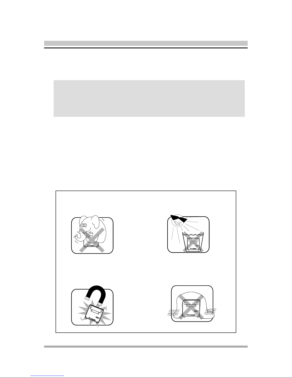
Installation Notices
Do not place this device
underneath heavy loads
or in an unstable position.
Do not expose this device to high
levels of direct sunlight, high-
humidity or wet conditions.
Do not use or expose this device
around magnetic elds as magnetic
interference may affect the
performance of the device.
Do not block the air vents
to this device or impede the
airow in any way.
Laser compliance statement
The optical disc drive in this server is a laser product. The drive's
classication label is lacated on the drive.
CLASS 1 LASER PRODUCT
CAUTION: INVISIBLE LASER RADIATION WHEN OPEN.
AVOID EXPOSURE TO BEAM.
CAUTION
Incorrectly replacing the battery may damage this computer. Replace only
with the same or equivalent as recommended by Shuttle. Dispose of used
batteries according to the manufacturer's instructions.

TABLE OF CONTENTS
Driver and Software Installation...................................................................................1
Mainboard Driver CD .............................................................................................1
User Manuals .................................................................................................2
Appendix......................................................................................................................3
Starting BIOS ..........................................................................................................3
Enter the BIOS ........................................................................................................3
Main Setup .....................................................................................................5
Advanced ........................................................................................................6
CPU Conguration .................................................................................7
IDE Conguration .................................................................................10
USB Conguration ...............................................................................13
Onboard Device Conguration .............................................................15
Power Management Conguration .......................................................17
Hardware Health Conguration ............................................................19
Frequency Voltage Conguration .........................................................20
Boot ............................................................................................................. 24
Boot Settings Conguration .................................................................24
Boot Device Priority ..............................................................................26
Hard Disk Drives ..................................................................................27
Security ........................................................................................................ 28
Exit ................................................................................................................30
1
English
Driver and Software Installation
Motherboard Driver CD
The Motherboard Driver CD contains all the motherboard drivers necessary to
optimize the performance of this Shuttle Xvision in a Windows® OS. Install these
drivers after installing Microsoft® Windows®.
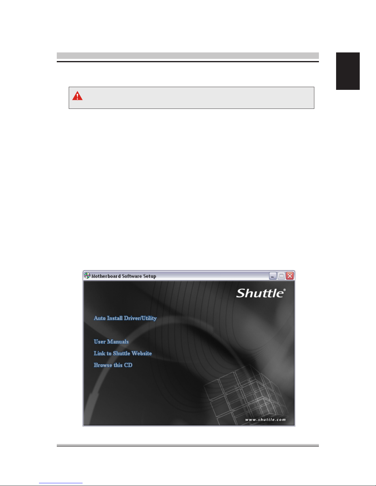
Insert the attached CD into your CD-ROM drive. The CD AutoRun screen should
appear. If the AutoRun screen does not appear, double click on Autorun icon in
My Computer to bring up Shuttle Mainboard Software Setup screen.
Navigation Bar Description :
Auto Install Driver/ Utility.
User Manuals - Motherboard Manual
, Quick Guide.
Link to Shuttle Website - Link to shuttle website homepage.
Browse this CD - Allows you to see contents of this CD.
The CD contents attached in SG41J1 Series motherboard are subject to
change without notice.
2
English
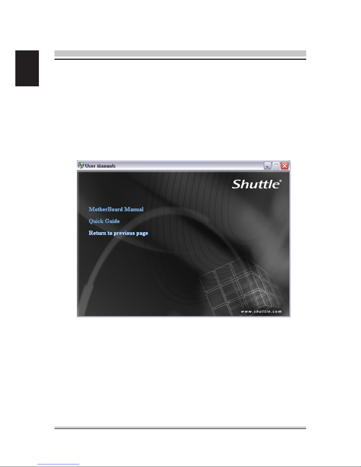
User Manuals
Motherboard Manual
Quick Guide
3
English
Starting BIOS
AMIBIOS has been integrated into many motherboards for over a decade. In the past,
people often referred to the AMIBIOS setup menu as BIOS, BIOS setup, or CMOS
setup.
American Megatrends refers to this setup as BIOS. Specically, it is the name of the
AMIBIOS8 BIOS setup utility. This chapter describes the basic navigation of the BIOS
setup screens.
Enter the BIOS
To enter the BIOS setup screens, follow the steps below:
Step1. Power on the motherboard.
Step2. Press the <Delete> key on your keyboard when you see the following
text prompt: Press DEL to run Setup.
Step3. After you press the <Delete> key, the main BIOS setup menu displays.
You can access the other setup screens from the main BIOS setup menu,
such as the Chipset and Power menus.
Appendix
BIOS Setup Menu
The main BIOS setup menu is the rst screen that you can navigate. Each main
BIOS setup menu option is described in this user’s guide.
The Main BIOS setup menu screen has two main frames. The left frame displays all
the options that can be congured. “Grayed-out” options cannot be congured.
Options is blue can be.
The right frame displays the key legend. Above the key legend is an area reserved for
a text message. When an option is selected in the left frame, it is highlighted in white.
Often a text message will accompany it.
This manual describes the standard look of the BIOS setup screen.
The motherboard manufacturer has the ability to change any and all of the
settings described in this manual. This means that some of the options
described in this manual do not exist in your motherboard's AMIBIOS.
In most cases, the <Delete> key is used to invoke the BIOS setup screen.
There are a few cases that other keys are used, such as <F1>,<F2>, and
so on.
4
English
The BIOS setup/utility uses a key-based navigation system called hot keys. Most of
the BIOS setup utility hot keys can be used at any time during the setup navigation
process. These keys include <F1>, <F10>, <Enter>, <ESC>, <Arrow> keys, and so
on.
Hot Key Description
→ Left
← Right
The Left and Right <Arrow> keys allow you to select a BIOS setup screen.
For example: Main screen, Advanced screen, Chipset screen, and so on.
↑ Up
↓ Down
The Up and Down <Arrow> keys allow you to select an BIOS setup item or sub-
screen.
+- Plus/Minus
The Plus and Minus <Arrow> keys allow you to change the field value of a
particular setup item. For example: Date and Time.
Tab The <Tab> key allows you to select BIOS setup elds.
F1
The <F1> key allows you to display the General Help screen.
Press the <F1> key to open the General Help screen.
F10
The <F10> key allows you to save any changes you have made and exit BIOS
Setup. Press the <F10> key to save your changes. Press the <Enter> key to save
the conguration and exit. You can also use the <Arrow> key to select Cancel and
then press the <Enter> key to abort this function and return to the previous screen.
ESC
The <Esc> key allows you to discard any changes you have made and exit the
BIOS Setup. Press the <Esc> key to exit the BIOS setup without saving your
changes. Press the <Enter> key to discard changes and exit. You can also use the
<Arrow> key to select Cancel and then press the <Enter> key to abort this function
and return to the previous screen.
Enter
The <Enter> key allows you to display or change the setup option listed for a
particular setup item. The <Enter> key can also allow you to display the setup sub-
screens.
AMIBIOS8 has default text messages built into it. The motherboard manufacture
retains the option to include, leave out, or change any of these text messages.
They can also add their own text messages. Because of this, many screen shots
in this manual are different from your BIOS setup screen.
There is a hot key legend located in the right frame on most BIOS setup screens.
The <F8> key on your keyboard is the Fail-Safe key. It is not displayed on the
BIOS key legend by default. To set the Fail-Safe settings of the BIOS, press the
<F8> key on your keyboard. It is located on the upper row of a standard 101
keyboard. The Fail-Safe settings allow the motherboard to boot up with the least
amount of options set. This can lessen the probability of conicting settings.
5
English
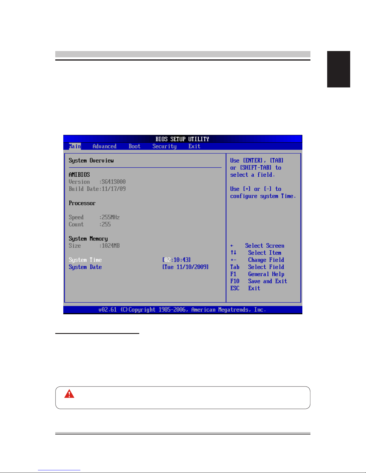
Main Setup
When you rst enter the BIOS Setup Utility, you will enter the Main setup screen.
You can always return to the Main setup screen by selecting the Main tab. There are
two Main Setup options. They are described in this section. The Main BIOS Setup
screen is shown below.
System Time/System Date
Use this option to change the system time and date. Highlight System Time or Sys-
tem Date using the <Arrow> keys. Enter new values through the keyboard. Press the
<Tab> key or the <Arrow> keys to move between elds. The date must be entered in
MM/DD/YY format. The time is entered in HH:MM:SS format.
The time is in 24-hour format. For example, 5:30 A.M. appears as 05:30:00,
and 5:30 P.M. as 17:30:00.

6
English
Advanced
Select the Advanced tab from the BIOS setup screen to enter the Advanced BIOS
Setup screen. You can select any of the items in the left frame of the screen, such as
CPU Conguration, to go to the sub menu for that item.
You can display an Advanced BIOS Setup option by highlighting it using the <Arrow>
keys. All Advanced BIOS Setup options are described in this section.
The Advanced BIOS Setup screen is shown below. The sub menus are described on
the following pages.

7
English
Hardware Prefetcher
When enabled, the processor's hardware prefetcher will be enabled and allowed
to automatically prefetch data and code for the processor. When disabled, the
processor's hardware prefetcher will be disabled.
The choice: Enabled or Disabled.
Adjacent Cache Line Prefetch
When enabled, the processor will retrieve the currently requested cache line,
as well as the subsequent cache line. When disabled, the processor will only
retrieve the currently requested cache line.
The choice: Enabled or Disabled.
CPU Conguration
You can use this screen to select options for the CPU Conguration Settings. Use the
up and down <Arrow> keys to select an item. Use the <Plus> and <Minus> keys to
change the value of the selected option. A description of the selected item appears
on the right side of the screen. The settings are described on the following pages. An
example of the CPU Conguration screen is shown below.
The CPU Conguration setup screen varies depending on the installed
processor.
 Loading...