

Page 1

XPC User Guide
For the : SD39P2
Page 2

Shuttle Mainb oard EMI Te st Statement
Shuttle mai nboards have been through EMI tests according to the following series of regulations:
EN55022/CISPR 22/AS/NZS3548 Class B, EN55024 (1998/AS/NZS), EN4252.1 (1994), EN61000,
ANSI C63.4 (1992), CFR47 Part 1 5 Subpart B, and CNS13438 (1997). The items tested are
illustrated as follows:
(A) Voltage: AC 110V/60HZ & AC 230V/50HZ
(B) Tested Product Information:
Product Name: PC Mainboard
Status: Sample
Model Name: SD39P2
S/N: N/A
CPU:
Intel Pentium 4, LGA 775 Core2 Extreme X6800 Conroe 2.93 GHz
FSB 1066 4M L2 cache B1 stepping
USB 2.0 Port: eight ports with 4 pi ns respectively
1394 Port: one ports with 4 pins and one ports with 6 pins respectively
LAN Port: one port with 8 pins (10M bps/100Mbps/1000Mbps)
Line-Out Ports: four ports
Front-Out Port: one port
Mic-In Ports: one port
Line-In Ports: one port
SPDIF-Out (Coaxial) Port: one port
SPDIF-Out (Optical) Port: one port
SPDIF-In (Optical) Port: one port
Clear CMOS button: one port
DIM M Memory (optional): DDR2 533/667 2GBx4
Power Cable: Detachable and Shielded (with a GND pin)
External Seri al-ATA II Port: one port with 7 pins
All C PUs have completely been tested, and values offered by the worst EMI combination of
CPU external frequency ar e listed as follows:
Test Mode External Frequency CPU CPU Open/Close
1 1066MH z Conroe 2.93 GHz Close
2 1066MH z Conroe 2.93 GHz Open
Page 3

(C) Remedy for the Tested Product & Its EMI Interference:
Remedy: N/A
EMI Interference:
Crystal : 14.318M Hz(X2)/ 25MHz(X3)/ 32.768KHz(X1)/ 24MHz(X7)
Clock Generator : U6
(D) Supported Host Peripherals:
Component Brand Model No. / Spec.
HDD x 1 Hita chi TEOMV90K
DVD-ROM BTC P10437007994
Memory x 2 Transcend 126589-0368(N H)/126589-0369(NH)
Power Shuttle PC43I3503
(E) Notices for Assembling Computers:
1. An I/O shielding should be contacted with I/O metallic parts of a mainboard.
2. Cables should appropriately be ar ranged and fixed in a case. Follow instructions:
Ø Leave IDE cables not crossed upon CPU and SDRAM ;
Ø Leave power cables minimum in length, and not crossed upon a mainboard;
Ø Leave CPU fan cables mini mum in length, and not near CPU;
Ø Leave cables on panels and other spare cables tied in a computer case.
3. Make sure an EMI shielding attached to a case has been properly installed.
4. Make sure a 5.25" drive and screw s are fastened to the case (EMI shielding).
5. Make sur e the case is in contact with EMI connection points.
6. Make sure there is no cleft in the case.
7. Make sure a PCI door is bound to a case.
8. Make sure cables of other devices (fans or some others) are fi xed in a case.
Page 4

Shuttle
®
XPC Installation Guide
Copyright
Copyright© 2007 by Shuttle® Inc. All Rights Reserved.
No part of this publication may be reproduced, transcribed, stored in a retrieval system,
translated into any language, or transmitted in any form or by any means, electronic,
mechanical, magnetic, optical, chemical, photocopying, manual, or otherwise, without prior
written permission from Shuttle® Inc.
Disclaimer
Shuttle® Inc. shall not be liable for any incidental or consequential damages resulting from
the performance or use of this product.
This company makes no representations or warranties regarding the contents of this manual. Information in this manual has been carefully checked for reliability; however, no
guarantee is given as to the correctness of the contents. In the interest of continued product
improvement, this company reserves the right to revise the manual or include changes in
the specifications of the product described within it at any time without notice and without
obligation to notify any person of such revision or changes. The information contained in
this manual is provided for general use by customers.
This device complies with Part 15 of the FCC Rules, Operation is subject to the following
two conditions:
1. This device may not cause harmful interference.
2. This device must accept any interference received, including interference that may
cause undesired operation.
Trademarks
Shuttle is a registered trademark of Shuttle Inc.
Intel and Pentium are registered trademarks of Intel Corporation.
PS/2 is a registered trademark of IBM Corporation.
AWARD is a registered trademark of Award Software Inc.
Microsoft and Windows are registered trademarks of Microsoft Corporation.
General Notice
Other brand and product names used herein are for identification purposes only and may
be trademarks of their respective owners.
Page 5
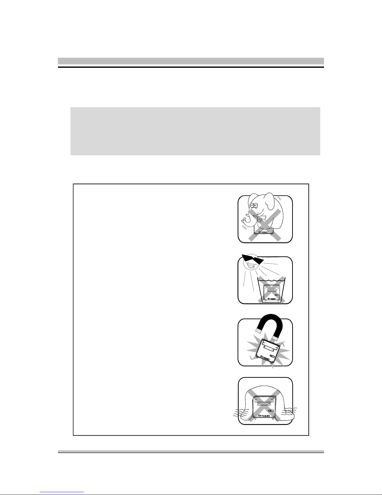
Inst allation Notices
Do not place this device underneath
heavy loads or in an unstable position.
Do not expose this device to high
levels of direct sunlight, high-humidity
or wet conditions.
Do not use or expose this device
around magnetic fields as magnetic
interfer ence may affect the
performance of the device.
Do not block the air vents to this
device or impede the airflow in
any way.
C AUTIO N
Incorrectly replacing the battery may damage this computer. Replace only with
the same or equivalent as recommended by Shuttle. Dispose of used batteries
according to the manufacturer's instructions.
Safety Information
Read the following precautions before setting up a Shuttle XPC.
Page 6

1 Driver and Software Installation ......................................................................... 1
1.1 Mainboard Driver CD................................................................................. 1
1.1.1 Install Mainboard Software..................................................................... 2
Appendix ............................................................................................................ 3
Enter the BIOS ................................................................................................. 3
THE MAIN MENU ............................................................................................ 4
Standard CMOS Features ................................................................................ 6
Advanced BIOS Features ................................................................................. 9
Advanced Chipset Features ........................................................................... 13
Integrated Peripherals .................................................................................... 15
Power Management Setup............................................................................. 19
PnP/PCI Configurations ................................................................................ 22
PC Health Status ........................................................................................... 24
Frequency Control ........................................................................................ 26
Load Fail-Safe Defaults .................................................................................. 28
Load Optimized Defaults ............................................................................... 28
Set Supervisor/User Password ........................................................................ 28
Save & Exit Setup .......................................................................................... 29
Exit Without Saving ....................................................................................... 29
TABLE OF CONTENTS
Page 7
1
English
< 1. 1 Mainboard Driver CD
The Mainboard Driver CD contains all the motherboard driver necessary to optimize
the performance of this XPC in a Windows(R) OS. Install these drivers after installing
Microsoft(R) Windows(R).
Navigation Bar Description :
F Install Mainboard Software - Intel Chipset Driver, Intel High Definition Audio
Driver, Broadcom Giga LAN Driver, Broadcom BACS, Intel Matrix stroage
Driver, Intel USB 2.0 Driver, DirectX9 Utility.
F Install Utility - Install Acrobat Reader, WinFlash Utility, XPC Tools.
F Manual - SD39P2 user's guide and RAID manual in PDF format.
F Link to Shuttle Homepage - Link to shuttle website homepage.
F Browse this CD - Allows you to see contents of this CD.
F Quit - Close this CD.
Note : The CD contents attached in SD39P2 mainboard are subject
to change without notice.
1 Driver and Software Installation
Page 8
2
English
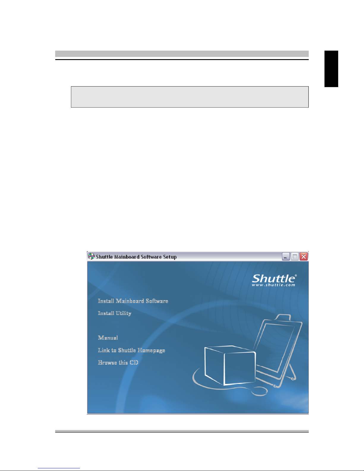
< 1.1.1 Install Mainboard Software
Insert the attached CD into your CD-ROM drive. The CD AutoRun screen should
appear. If the AutoRun screen does not appear, double click on Autorun icon in My
Computer to bring up Shuttle Mainb-oard Software Setup screen.
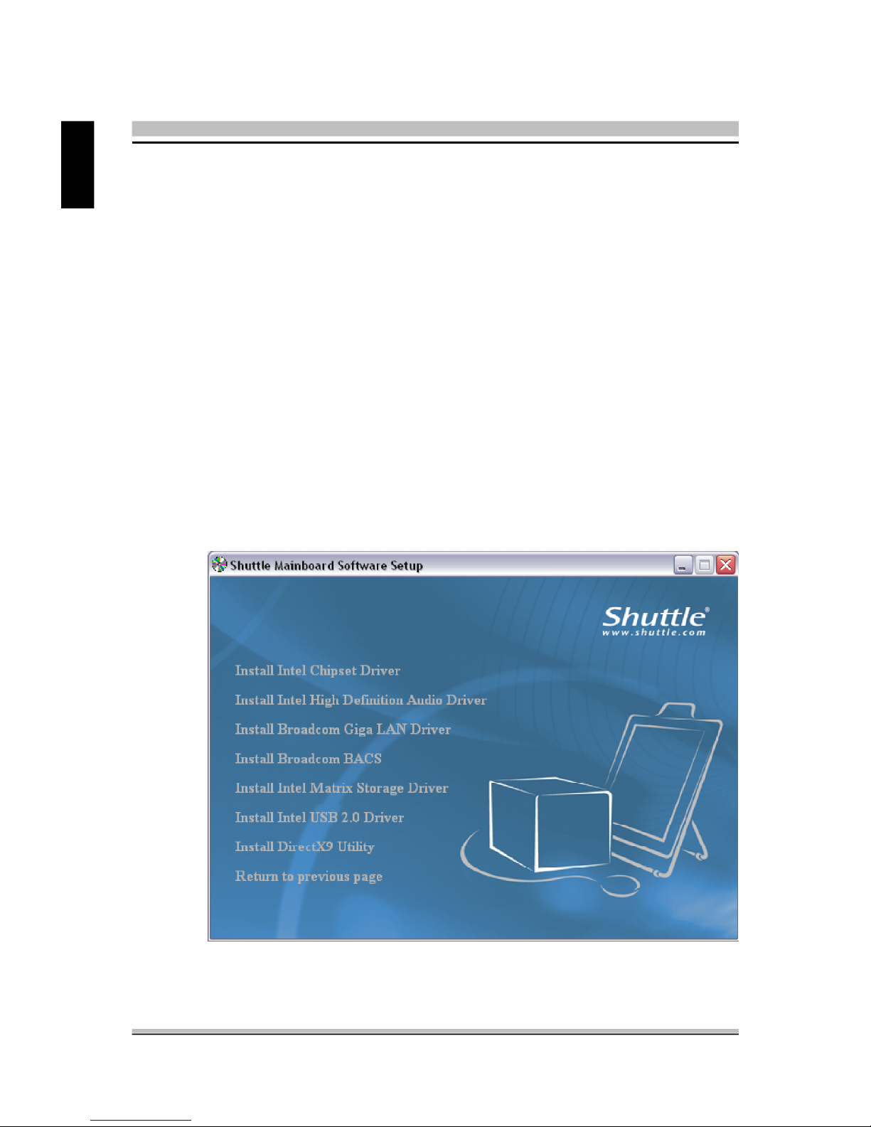
Click the “Install Main-board Software“ bar. Individually install the following drivers.
E Install Intel Chipset Driver
E Install Intel High Definition Audio Driver
E Install Broadcom Giga LAN Driver
E Install Broadcom BACS
E Install Intel Matrix Stroage Driver
E Install Intel USB 2.0 Driver
E Install DirectX9 Utility
Page 9

3
English
BIOS Settings
The SD39P2 BIOS ROM has a built-in Setup program that allows users to modify basic
system configuration. This information is stored in battery-backed RAM so that it retains Setup information even if the system power is turned off.
The system BIOS manages and executes a variety of hardware related functions
including:
System date and time
Hardware execution sequence
Power management functions
Allocation of system resources
Enter the B IOS
To enter the BIOS (Basic Input / Output System) utility, follow these steps:
Step1. Power on the computer. The system will perform its POST (Power-On
Self Test) routine checks.
Step2. Press the <Del> key immediately, or at the following message:
Press DEL to enter SETUP, or simultaneously press <Ctrl>,<Alt>,
<Esc> keys
Note 1. If you miss the train of words mentioned in step2 (the message disap-
pears before you can respond) and you still wish to enter BIOS Setup,
restart the system and try again by turning the computer OFF and
ON again or by pressing the <RESET> switch located at the
computer’s front-panel. You may also reboot by simultaneously
pressing the <Ctrl>,<Alt>, <Del> keys simultaneously.
Note 2. If you do not press the keys in time and system does not boot, the
screen will prompt an error message, and you will be given the
following options:
"Press F1 to Continue, DEL to Enter Setup”
Step3. When you enter the BIOS program, the CMOS Setup Utility will display the
Main Menu, as shown in the next section.
Appendix
Page 10
4
English
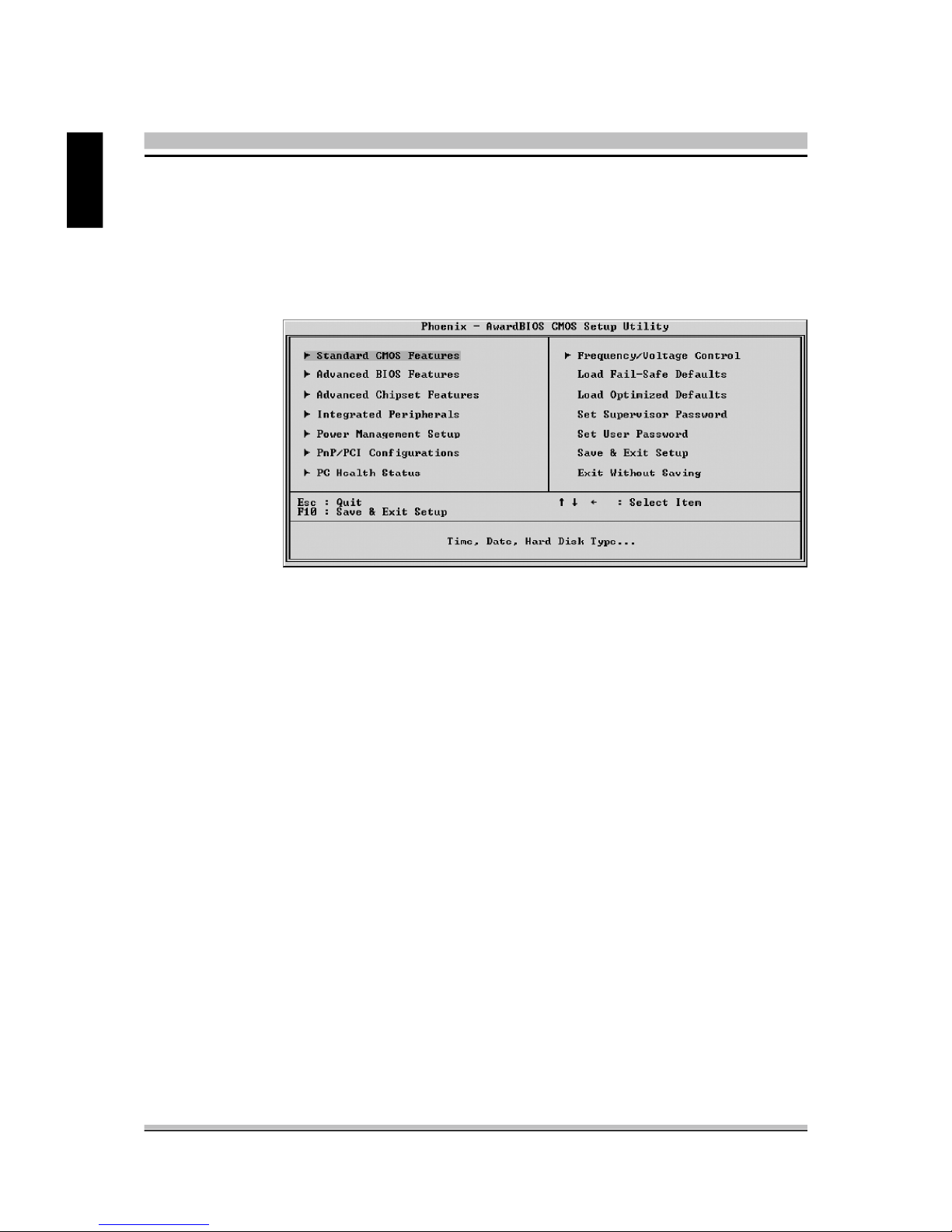
The Main Menu
Once you enter the AwardBIOS(tm) CMOS Setup Utility, the Main Menu
will appear on the screen. The Main Menu allows you to select from several setup functions and two exit choices. Use the arrow keys to select
among the items and press <Enter> to accept and enter the sub-menu.
Note that a brief description of each highlighted selection appears at the
bottom of the screen.
Setup Items
The main menu includes the following main setup categories. Recall that
some systems may not include all entries.
Standard CMOS Features
Use this menu for basic system configuration.
Advanced BIOS Features
Use this menu to set the Advanced Features available on your system.
Advanced Chipset Featur es
Use this menu to change the values in the chipset registers and optimize
your system's performance.
Integrated Peripherals
Use this menu to specify your settings for integrated peripherals.
Power Management Setup
Use this menu to specify your power management settings.
PnP / PCI Configurations
This entry appears if your system supports PnP / PCI.
Page 11

5
English
PC Health Status
This entry displays the current system temperature, Voltage, and FAN
settings.
Frequency/Voltage Control
Use this menu to specify your settings for frequency/voltage control.
Load Fail-Safe Defaults
Use this menu to load the BIOS default values for the minimal/stable performance of your system to operate.
Load Optimized Defaults
Use this menu to load the BIOS default values that are factory-set for optimal system operation. While Award has designed the custom BIOS to
maximize performance, the factory has the right to change these defaults
to meet users' needs.
Set Super visor / User Password
Use this menu to change, set, or disable password protection. This allows
you to limit access to the system and Setup, or only to Setup.
Save & Exit Setup
Save CMOS value changes in CMOS and exit from setup.
Exit Without S aving
Abandon all CMOS value changes and exit from setup.
Page 12

6
English
@ Standard CMOS Features
The items in the Standard CMOS Setup Menu are divided into several
categories. Each category includes none, one or more than one setup
items. Use the arrow keys to highlight the item and then use the <PgUp>
or <PgDn> keys to select the value you want in each item.
Date
<Month> <DD> <YYYY>
Set the system date. Note that the 'Day' automatically changes when you
set the date.
Time
<HH : MM : SS>
The time is converted based on the 24-hour military-time clock.
For example, 5 p.m. is 17:00:00.
IDE Channel 0/1 Master/Slave
Options are in its sub-menu.
Press <Enter> to enter the sub-menu of detailed options.
Drive A
Select the type of floppy disk drive installed in your system.
Ø The choice: None, 360K, 5.25 in, 1.2M, 5.25 in, 720K, 3.5 in,
1.44M, 3.5 in, or 2.88M, 3.5 in.
Video
Select the default video device.
Ø The choice: EGA/VGA, CGA 40, CGA 80, or MONO.
Page 13

7
English
Halt On
Select the situation in which you want the BIOS to stop the POST process
and notify you.
Ø The choice: All Errors, No Errors, All, But Keyboard,
or All, But Diskette, All, But Disk/Key.
Base Memory
Displays the amount of conventional memory detected during boot up.
Ø The choice: N/A.
Extended Memory
Displays the amount of extended memory detected during boot up.
Ø The choice: N/A.
Total Memory
Displays the total memory available in the system.
Ø The choice: N/A.
******************************************************
IDE Adapters
The IDE adapters control the hard disk drive. Use a separate sub-menu to
configure each hard disk drive.
IDE HDD Auto-Detection
Press <Enter> to auto-detect HDD on this channel. If detection is
successful, it fills the remaining fields on this menu.
Ø Press Enter
IDE Channel 0/1 Master/Slave
Selecting 'manual' lets you set the remaining fields on this screen and
select the type of fixed disk. "User Type" will let you select the number of
cylinders, heads, etc., Note: PRECOMP=65535 means
NONE !
Ø The choice: None, Auto, or Manual.
Access Mode
Choose the access mode for this hard disk.
Ø The choice: CHS, LBA, Large, or Auto.
Page 14

8
English
Capacity
Disk drive capacity (Approximated). Note that this size is usually slightly
greater than the size of a formatted disk given by a disk checking program.
Ø Auto-Display your disk drive size.
The following options are selectable only if the 'IDE Primary Master'
item is set to 'Manual', and Access mode set to CHS.
Cylinder
Set the number of cylinders for this hard disk.
Ø Min = 0, Max = 65535
Head
Set the number of read/write heads.
Ø Min = 0, Max = 255
Precomp
Warning: Setting a value of 65535 means no hard disk.
Ø Min = 0, Max = 65535
Landing zone
Set the Landing zone size.
Ø Min = 0, Max = 65535
Sector
Number of sector per track.
Ø Min = 0, Max = 255
******************************************************
Page 15

9
English
@ Advanced BIOS Features
This section allows you to configure your system for basic operation. You
have the opportunity to select the system's default speed, boot-up sequence,
keyboard operation, shadowing, and security.
CPU Feature
Options are in its sub-menu.
Press <Enter> to enter the sub-menu of detailed options.
Delay Prior to Thermal
This item is select Delay Prior to Thermal.
Ø The Choice: 4Min, 8Min, 16Min or 32 Min.
Thermal Management
This item is select Thermal Management . Thermal Monitor 1 (On die
throtting). Thermal Monitor 2 Ratio & VID transition ).
Ø The Choice: Thermal Monitor 1 or Thermal Monitor 2.
TM2 Bus Ratio
Represents the frequency (bus ratio of the throttled performance statethat
will be initiated when the on-diesensor gose from not hot to hot.
Ø The Choice: Min=0 Max=255.
Note: CPU support TM2, item appear.
Page 16

10
English
TM2 Bus VID
Represents the voltageof the throttled performance statethat will be initiated when the on diesensor gose from not hot to hot.
Ø The Choice: 0.8375V ~1.6000V.
Note: CPU support TM2, item appear.
Limit CPUID MaxVal
Set Limit CPUID MaxVal to 3,Should Be "Disabled" for WinXp.
Ø The Choice: Disabled or Enabled.
Note: Some older O.S.'s (Win98,WinMe..) cannot handle a CPUID
MaxVal greater than 3. Please choose "Enabled" if you use one
of those O.S. If your O.S. is WinXP or Win2000, we suggest you
"Disabled" the item.
C1E Function
When disabled, processor can't transitions to a lower core frequency and
voltage.
Ø The Choice: Auto or Disabled.
Execute Disable Bit
When disabled, forces the XD feature flag to always return 0.
Ø The Choice: Enabled or Disabled.
Virtualization Technology
When enabled, a VMM can utilize the additional hardwarecapabilities
provided by Vanderpool Technology.
Ø The Choice: Enabled or Disabled.
Hard Disk Boot Priority
This item allows you to select Hard Disk Book Device Priority.
Bios Write Protect
This item allows you to enable or disable the Bios Write Protect.
If you want to flash BIOS, you must set it [Disabled].
Ø The choice: Enabled or Disabled.
Virus Warning
Allows you to choose the VIRUS Warning feature for IDE Hard Disk boot
sector protection. If this function is enables and someone attempts to write
data into this area, BIOS will show a warning message on screen, and an
alarm beep.
Page 17

11
English
Enabled Activates automatically when the system boots up, causing a
warning message to appear when anything attempts to access
the boot sector or hard disk partition table.
Disabled No warning message will appear when anything attempts to
access the boot sector or hard disk partition table.
Ø The choice: Enabled or Disabled.
CPU L1&L2&L3 Cache
All processors that can be installed in this mainboard use internal level1
(L1) , external 2(L2) and (L3) cache memory to imporve performance.
Leave this item at the default value for better performance.
Ø The choice: Enabled or Disabled.
Note : CPU support, L3 item appear.
Hyper-Threading Technology
The latest Intel application defines a high-speed calculating ability to optimize your system by two CUPs supported(one virtual, one physical) in a
multi-task environment. "Enabled" for Windows XP and Linux 2.4.x(OS
optimized for Hyper Threading Technology and "Disable" for other OS
(OS not optimized for Hyper Threading Technology)
Ø The choice: Enabled, or Disabled.
Note : CPU support, Hyper-Threading item appear.
Quick Power On Self Test
This item speeds up Power-On Self Test (POST) after you power on the
computer. If it is set to enabled, BIOS will shorten or skip some check
items during POST.
Ø The choice: Enabled, or Disabled.
First/Second/Third Boot Device
The BIOS attempts to load the operating system from the devices in the
sequence selected in these items.
Ø The Choice: LS120, Hard Disk, CDROM, ZIP100, USB-FDD,
USB-ZIP,USB-CDROM, LAN, Disabled or Floppy.
Boot Other Device
If BIOS can't load O.S. from First/Second/Third boot device you select
above, BIOS will search other devices and attempt to load O.S..
Ø The choice: Enabled or Disabled.
Page 18

12
English
Boot Up Floppy Seek
Enabled tests floppy drives to determine whether they have 40 or 80 tracks
Ø The choice: Enabled or Disabled.
Boot Up NumLock Status
Selects power on state for NumLock.
Ø The choice: Off or On.
Gate A20 Option
This entry allows you to select how the Gate A20 is handled. The gate
A20 is a device used for above 1MByte of address memory. Initially, the
gate A20 was handled via a pin on the keyboard. Today, while a keyboard still provides this support, it is more common and much faster in
setting to fast for the system chipset to provide support for gate A20.
Ø The choice: Normal or Fast.
Security Option
Select whether the password is required every time the system boots or
only when you enter setup.
System The system will not boot and access to Setup will be denied
if the correct password is not entered promptly.
Setup The system will boot, but access to Setup will be denied if the
correct password is not entered promptly.
Ø The choice: System or Setup.
Note : To disabled security, select PASSWORD SETTING at Main
Menu, and then you will be asked to enter password. Don't
type anything and just press <Enter>; it will disable security.
Once the security is disabled, the system will boot, and you
can enter Setup freely.
APIC Mode
Via the routing, I/O APIC support a total of 24 interrupts. We recommend
to choose [Enabled] for Windows XP and Windows 2000.
Ø The choice: Enabled or Disabled.
MPS Version Control For OS
Selects the operating system multiprocessor support version.
Ø The choice: 1.1 or 1.4
Page 19

13
English
@ Advanced Chipset Features
This section allows you to configure the system based on the specific features
of the installed chipset. This chipset manages bus speeds and access to system memory resources, such as DRAM and the external cache. It also coordinates communications between the conventional ISA bus and the PCI bus.
It states that these items should never need to be altered.
The default settings have been chosen because they provide the best operating conditions for your system. If you discovered that data was being lost
while using your system, you might consider making any changes.
System BIOS Cacheable
Selecting Enabled allows caching of the system BIOS ROM at
F0000h~FFFFFh, resulting in better system performance. However, if any
program is written to this memory area, a system error may result.
Ø The Choice: Enabled or Disabled.
Video BIOS Cacheable
Selecting Enabled allows caching of the video BIOS, resulting in better
system performance. However, if any program is written to this memory
area, a system error may result.
Ø The Choice: Enabled or Disabled.
Memory Hole At 15M-16M
You can reserve this area of system memory for ISA adapter ROM. When
this area is reserved, it can't be cached. The user information of peripher
Page 20

14
English
als that need to use this area of system memory usually discusses their
memory requirements.
Ø The Choice: Enabled or Disabled.
DRAM Data Integrity Mode
This item allows you to set DRAM Data Integrity Mode.
Ø The choice: ECC or Non-ECC .
PEG Force X1
This item allows you to force PEG link X1.
Ø The Choice: Enabled, or Disabled.
Page 21

15
English
@ Integrated Peripherals
On-Chip IDE Device
Option are in its sub-menu.
Press<Enter>to enter the sub-menu of detailed options.
IDE HDD Block Mode
If your IDE hard disk drive supports block mode (most new drives do),
select Enabled to automatic detect the optimal number of block read and
writes per sector that the drive can support and improves the speed of
access to IDE devices.
Ø The choice: Enabled, or Disabled.
On-Chip Primary PCI IDE
Use these items to enable or disable the PCI IDE channels that are
integrated on the mainboard.
Ø The choice: Enabled or Disabled.
IDE Primary Master/Slave PIO
Each IDE channel supports a master device and a slave device. These
four items let you assign which kind of PIO ( Programmed Input / Output
) is used by IDE devices. Choose Auto to let the system auto detect which
PIO mode is best or select a PIO mode from 0-4.
Ø The choice: Auto, Mode 0, Mode 1, Mode 2, Mode 3, or Mode 4.
Page 22

16
English
IDE Primary Master/Slave UDMA
Each IDE channel supports a master device and a slave device. This
mainboard supports UltraDMA technology, which provides faster access
to IDE devices.
If you install a device that supports UltraDMA, change the appropriate
item on this list to Auto. You may have to install the UltraDMA driver
supplied with this mainboard in order to use an UltraDMA device.
Ø The Choice: Auto or Disabled.
********** On -Chip Serial ATA Setting **********
SATA Mode
This item allows you to set the SATA Mode.
Ø The choice: IDE, RAID or AHCI.
On-Chip Serial ATA
Ø The Choice: Disabled, Enhanced Mode or SATA Only.
Disabled : Disabled SATA Controller.
SATA4
SATA1
SATA3
Disable
SATA2Parallel ATA
IDE1 (Channel 0 Master)
IDE1 (Channel 0 Slave)
Page 23

17
English
SATA-Only :SATA operates in legacy mode.
Enhanced Mode: Enables both SATA and PATA. Max. 2 ATA drives are
supported. Some current operationg systems (WinXP,Windows NET
Server,Windows2000) support Enhanced mode.
SATA1 (Channel 0 Master)
SATA2 (Channel 0 Slave)
SATA3 (Channel 1 Master)
SATA4 (Channel 1 Slave)
SATA4
SATA1
SATA3
SATA2Parallel ATA
Disable
SATA1 (Channel 2 Master)
SATA2 (Channel 2 Slave)
SATA3 (Channel 3 Master)
SATA4 (Channel 3 Slave)
SATA4
SATA1
SATA3
SATA2Parallel ATA
IDE1 (Channel 0 Master)
IDE1 (Channel 0 Slave)
Page 24

18
English
SATA PORT Speed Settings
This item allows you to set the SATA PORT Speed.
Ø The choice: Disabled, Force GEN I, or Force GEN II.
Onboard Device
Option are in its sub-menu.
Press<Enter>to enter the sub-menu of detailed options.
USB Controller
Select Enabled if your system contains a Universal Serial Bus (USB) port
on this mainboard.
Ø The choice: Enabled or Disabled.
USB 2.0 Controller
Select Enabled if your system contains a Universal Serial Bus (USB) 2.0
controller and you have USB peripherals.
Ø The choice: Enabled or Disabled.
High Definition Audio
Use these items to enable or disable the High Definition Audio.
Ø The choice: Enabled or Disabled.
Onboard Lan Boot ROM
Decide whether to invoke the boot ROM of the onboard LAN chip.
Ø The Choice: Enabled or Disabled.
SuperIO Device
Option are in its sub-menu.
Press<Enter>to enter the sub-menu of detailed options.
Onboard FDC Controller
This item specifices onboard floppy disk drive controller. This setting
allows you to connect your floppy disk drives to the onboard floppy
connector.
Ø The choice: Enabled or Disabled.
Page 25

19
English
@ Power Management Setup
The Power Management Setup allows you to configure your system to
most effectively save energy while operating in a manner consistent with
your computer usage.
ACPI Suspend Type
This item allows you to select sleep state when suspend.
Ø The choice: S1(POS) or S3(STR).
Run VGABIOS if S3 Resume(Auto)
This item allows the system to initialize the VGA BIOS from S3(Suspend to RAM) sleep state.
Ø The choice: Auto, Yes or No.
Power Management
This item allows you to decide the timing to enter suspend mode.
Ø The choice: User Define, Min Saving, Max Saving.
Video Off Method
This determines the manner in which the monitor is blanked.
V/H SYNC+Blank This selection will cause the system to turn off
the vertical and horizontal synchronization
ports and write blanks to the video buffer.
Blank Screen This option only writes blanks to the video
buffer.
DPMS Initial display power management signaling.
Ø The choice: V/H SYNC+Blank, Blank Screen, or DPMS.
Page 26

20
English
Video Off In Suspend
This item determines the manner in which the monitor is blanked.
Ø The choice: Yes or No.
Suspend Type
This item allows you to select the Suspend Type.
Ø The choice: Stop Grant or PwrOn suspend.
Suspend Mode
When this item enabled and after the set up time of system inactivity, all
devices except the CPU will be shut off.
Ø The choice: Disabled, 1Min, 2Min, 4Min, 8Min, 12Min, 20Min,
30Min, 40Min, or 1Hour.
HDD Power Down
When this item enabled and after the set up time of system inactivity, the
hard disk drive will be powered down while all other devices remain
active.
Ø The choice: Disabled or 1 Min~15 Min.
Soft-Off by PWR-BTTN
Under ACPI you can create a software power down. In a software power
down, the system can be resumed by Wake UP Alarms. This item lets you
install a software power down that is controlled by the power button on
your system. If the item is set to Instant-Off, then the power button causes
a software power down. If the item is set to Delay4 Sec. then you have to
hold the power button down for 4 seconds to cause a software power
down.
Ø The choice: Instant-Off or Delay 4 Sec.
Resume by Alarm
When this item enabled, your can set the date (day of the month) and
time to turn on your system.
Ø The choice: Disabled or Enabled.
Date(of Month) Alarm
This item selects the alarm Date (day of the month).
Ø Key in a DEC number: Min=0, Max=31.
Time(hh : mm : ss) Alarm
This item selects the alarm Time.
[hh] Ø Key in a DEC number: Min=0, Max=23.
[mm/ss] Ø Key in a DEC number: Min=0, Max=59.
Page 27

21
English
Pwron After PWR-Fail
This item defines if the system will be rebooted after the power fails.
Ø The choice: Off, On, Former-Sts.
Page 28

22
English
@ PnP/PCI Configurations
This section describes the configuration of PCI bus system. PCI or Personal Computer Interconnection is a system which allows I/O devices to
operate at the speed CPU itself keeps when CPU communicating with its
own special components.
This section covers some very technical items, and it is strongly recommended that only experienced users should make any changes to the
default settings.
Init Display First
This item allows you to decide to activate whether PCI slot or PCI Ex
slot first. Dual display function: Before using PCI VGA card to build
dual display function with onboard VGA under OS, please select PCIE
Slot/PCI Ex item first.
Ø The Choice: PCI Slot or PCI Ex.
Reset Configuration Data
Normally, you leave this field Disabled. Select Enabled to reset
Extended System Configuration Data (ESCD) when you exit from Setup
if you have installed a new device or software and the system
reconfiguration has caused such a serious conflict that the operating system can not boot.
Ø The choice: Enabled or Disabled .
Page 29

23
English
Resource controlled By
The Award Plug-and-Play BIOS has the capacity to automatically configure a ll of th e boot a nd Plug -an d-P lay c omp at ibl e de vic es.
However, this capability means absolutely nothing unless you are using a
Plug-and-Play operating system such as Windows 95.
If you set this field to "manual" , choose specific resources by going into
each of the sub-menu that follows this field (a sub-menu is proceeded by
a ">").
Ø The choice: Auto(ESCD) or Manual.
IRQ Resources
When resources are controlled manually, assign each system interrupt a
type, depending on the type of device using the interrupt.
IRQ3/4/5/7/10/11/12/14/15 assigned
This item allows you to determine the IRQ assigned to the ISA bus and is
not available to any PCI slot. Legacy ISA for devices is compliant with the
original PC AT bus specification; PCI/ISA PnP for devices is compliant
with the Plug-and-Play standard whether designed for PCI or ISA bus architecture.
Ø The choice: PCI Device or Reserved.
PCI/VGA Palette Snoop
It determines whether the MPEG ISA/VESA VGA Cards can work with
PCI/VGA or not. If you have MPEG ISA/VESA VGA Cards and PCI/VGA
Card worked, Enable this field. Otherwise, please Disable it.
Ø The choice: Enabled or Disabled.
INT Pin1~8 Assignment
Names the interrupt request(IRQ) line assigned to a device connected to
the PCI interface on your system.
Ø The choice: Auto, 3, 4, 5, 7, 9, 10, 11, 12, 14, 15.
********** PCI Express relative items **********
Maximum Payload Size
Set maximum TLP payload size for the PCI Express devices.
The unit is byte.
Ø The choice: 4096, 2048, 1024, 512, 256 or 128.
Page 30

24
English
@ PC Health Status
Advanced CPU Fan Setting
Here you can set the CPU Fan Speed.
Ø The choice: Smart Fan Mode, Ultra-Low Fan Speed, Low Fan Speed,
Mid Fan Speed, Full Fan Speed or Extreme PC Mode.
Note : Before manually modifying the CPU fan setting, please make
sure fan connectors are plug ged into the correct fan connector on the mainboard.
System Fan Setting
Here you can set the System Fan Speed.
Ø The choice: Ultra-Low Fan Speed, Low Fan Speed, Mid Fan Speed,
or Full Fan Speed.
LED Bright Setting
Here you can set the LED Bright.
Ø The choice: 0%, 25%, 37.5%, 50%, 62.5%, 75%, 87.5% or 100%.
Page 31

25
English
CPU Voltage
ChipSet Voltage
+3.3V
+5V
+12V
DDR2 Voltage
+5VSB
Voltage Battery
CPU Temperature
System Temperature
Fan 1 Speed
Fan 2 Speed
Fan 3 Speed
Fan 4 Speed
Warning : It is Strongly reco-mmended to disable 'Smart Fan' if
you use an alternative fan to the default.
Page 32

26
English
@ Frequency/Voltage Control
Spread Spectrum
This item allows you to enable or disable the spread spectrum modulation.
Ø The choice: Disabled or Enabled.
DRAM Timing Selectable
The value in this field depends on performance parameters of the installed
memory chips(DRAM). It is recommended that you don't change the value
from the factory setting unless you install new memory that has a different
performance rating than the original DRAMs.
Ø The Choice: Manual or By SPD
CAS Latency Time
When synchronous DRAM is installed, the number of CAS latency clock
cycles depends on the DRAM timing. It is recommended don't change
this field from the default value specified.
Ø The Choice: Auto, 3, 4, 5 or 6.
DRAM RAS # to CAS # Delay
This field lets you insert a timing delay between the CAS and RAS strobe
signals when DRAM is written to, read from, or refreshed. Faster performance is gained at high speed, more stable performance, at low speed.
This field is applied only when synchronous DRAM
is installed in the system.
Ø The Choice: Auto, 2, 3, 4, 5 or 6.
Page 33

27
English
DRAM RAS # Precharge
If an insufficient number of cycles is allowed for the RAS to accumulate its
charge before DRAM refresh, the refresh may not complete, and the DRAM
may fail to retain data. High gives faster performance; and Slow gives
more stable performance. This field is applicable only when synchronous
DRAM is installed in the system.
Ø The Choice: Auto, 2, 3, 4, 5 or 6.
Precharge delay (tRAS)
This item allows you to set Precharge delay (tRAS).
Ø The Choice: 4~18 or Auto.
System Memory Frequency
This item allows you to set System Memory Frequency.
Ø The Choice: 533MHz, 667MHz,800MHz or Auto.
****** Clock ******
CPU Clock Ratio
This item allows the user to adjust CPU Clock Ratio.
If CPU is unlocked, item appear.
Ø The Choice: 8X~50X.
CPU Clock
This item allows the user to adjust CPU Host Clock.
Min: 133 Max: 400
Ø Key in a DEC number: (Between Min and Max.)
PCIEX CLK
This item allows you to set PCIEX CLK.
Ø The choice: Fixed 100 MHz or Sync by CPU clock.
****** Voltage ******
CPU Voltage set
This item allows you to set CPU Voltage.
Ø The choice: +25mv~800mV or Auto.
DDR2 Voltage set
This item allows you to set DDR2 Voltage.
Ø The choice: Auto, 2.0V, 2.2V or 2.4V.
Page 34

28
English
@ Set Supervisor/User Password
Steps to set supervisor/user password are described as follows:
@ Load Fail-Safe Defaults
When you press <Enter> on this item, you will get a confirmation
dialog box with a message similar to:
Load Fail-Safe Defaults (Y/N) ? N
Pressing 'Y' loads the BIOS default values for the most stable, minimal
performance system operations.
@ Load Optimized Defaults
When you press <Enter> on this item, you will get a confirmation
dialog box with a message similar to:
Load Optimized Defaults (Y/N) ? N
Pressing 'Y' loads the default values that are factory-set for optimal
performance system operation.
Page 35

29
English
New Password Setting:
1. While pressing <Enter> to set a password, a dialog box appears to
ask you enter a password.
2. Key in a new password. The password can not exceed eight characters.
3. System will request you to confirm the new password again.
4. When completed, new code takes effect.
No Password Setting:
5. If you want to delete the password, just press the <Enter> key
instead of typinga new password. Follow the procedure as ablve.
If You Forget Password:
6. If you forget your password, you must turn off the system and clear
CMOS. Please refer to the tech notes at the end of section two for more
information.
@ Save & Exit Setup
Pressing <Enter> on this item asks for confirmation:
SAVE to CMOS and EXIT (Y/N)? Y
Pressing "Y" stores the selections made in the menus of CMOS - a special
section of memory that stays on after you turn your system off. The next
time you boot your computer, the BIOS configures your system according to the Setup selections stored in CMOS. After saving the values the
system is restarted again.
@ Exit Without Saving
Pressing <Enter> on this item asks for confirmation:
Quit Without Saving (Y/N)? N
This allows you to exit from Setup without storing in CMOS any change.
The previous selections remain in effect. This exits from the Setup utility
and restarts your computer.
 Loading...