

Page 1
Product Specifications
w w w . s h u t t l e . e u
Shuttle C o m p u t e r H a n d e l s G m b H
Fr it z- St ras sma nn-S tr . 5
25 337 El msh or n | Ge r ma n y
Te l. +4 9 ( 0 ) 412 1 -4 7 6 8 6 0
Fa x + 4 9 ( 0) 41 21- 47 69 00
sa les @sh ut tle .eu
Page 1 2 1 N ovember 20 19
© 2019 by Shuttle Computer Handels GmbH (Germany). All information subject to change without notice
. Pictures for illustration purposes only.
Expansion kit for DS10U
to install a LTE/4G card
The Shuttle XPC accessory WWN03 allows the Shuttle XPC slim
Barebo ne DS10U to be upgraded with an LTE/4G fu nction for mo bile
network. The LTE card will occupy the 2.5" bay, so you have to use an
M.2 SSD as ma ss storage device. The requi red LTE/4G ca rd in M.2 3042 format and an activated Nano SIM c ard is not included in the
scope of de livery. The existing WLAN fu nctio n of DS10U can still be
used then.
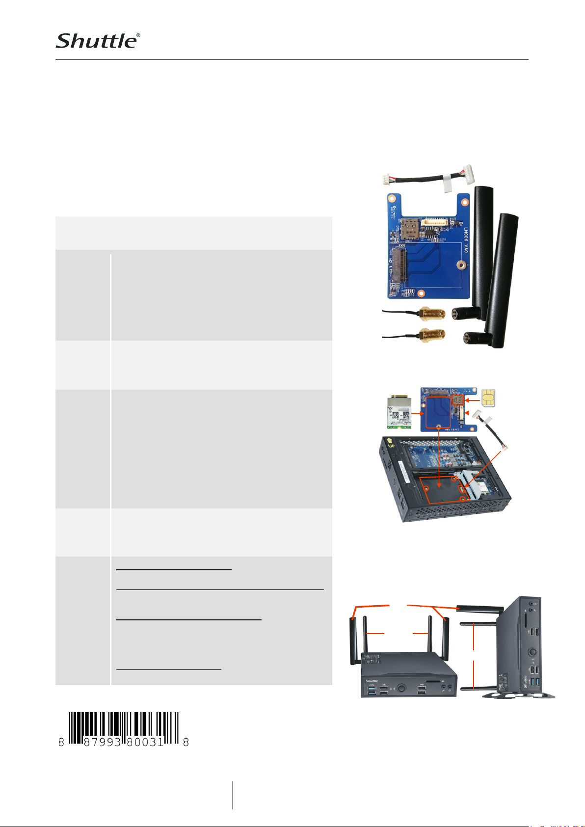
Feature Highlights
Contents
Daughterboard LN006 with USB cable
Fastening screw for M.2/LTE card (two -parts: bolt
with screw)
3x screw to install LN006 in a 2.5” bay
2x LTE/4G antennas
2x antenna cables with toothed lock washer and
screw nut
Quick installation guide
Adapter
card
USB connector to connect to the mainboard
M.2 socket supports one LTE/4G mo dule M.2-
3042 Key B
Supports one SIM card in Nan o format
Two external
antennas
LTE/4G dipole omnidirectional antenna
Multi-band: supports EU frequency bands (800,
1800, 2600 MHz) for GSM/UMTS/LTE and the
following frequency ranges: 704~960, 1428~1575,
1720~2170, 2400~2690 MHz
Colour: black , Lengt h overall: 135.7 mm
Dimensions of the antenna body: 114.8 x 20.1 mm
Impedance: 50 Ohm
Voltage Standing Wave Ratio (VSWR): <= 3.0
Radiat ion: Omni, Gain: 2 dBi, Polarisation: vert ical
Connector: SMA
Two antenna
cables
RF cable lengths: 20 cm
Connectors:
1) SMA Pigtail female
2) I-PEX MHF 4
Compat ibility
The WWN03 can be used for
- Shuttle XPC slim DS10U
Additional components are required for operation:
- L TE/4G module M.2-3042 Key B
- SIM card in Nano format
Successfully tested LTE/4G modules:
- Sierra EM7455 (CAT 6, for EMEA,North America)
- Sierra EM7430 (CAT 6, for APAC)
- Huawei ME906S (CAT 4, for EMEA, Australia, NZL)
- Quectel EM06-E (CAT 6, for EMEA, Australia, Brazil)
WWN03 is not compatible to LTE cards with PCIe
interface e.g. Fibocom L850-GL-00 LTE m odule
Shuttle XPC accessory
WWN03
Expansion kit for LTE/4G module
and Nano SIM card
Shuttle XP C accessory WWN03
The 2.5” bay will be occupied by the WWN03 kit
and you have to use a M.2 SSD card.
The LTE module and SIM card is not included.
Images for illustration
purposes only.
M.2
LTE
Nano
SIM
USB
DS10U
Note: If the DS10U is operated in vertical position
with the stand, you cannot install an antenna at
the bottom side. This means only 3 antennas can
be used for WLAN and LTE in total (either LTE or
WLAN will have to work with one antenna only).
LTE
WLAN
WLAN
Page 2
Product Specifications
w w w . s h u t t l e . e u
Shuttle C o m p u t e r H a n d e l s G m b H
Fr it z- St ras sma nn-S tr . 5
25 337 El msh or n | Ge r ma n y
Te l. +4 9 ( 0 ) 412 1 -4 7 6 8 6 0
Fa x + 4 9 ( 0) 41 21- 47 69 00
sa les @sh ut tle .eu
Page 2 2 1 N ovember 20 19
© 2019 by Shuttle Computer Handels GmbH (Germany). All information subject to change without notice
. Pictures for illustration purposes only.
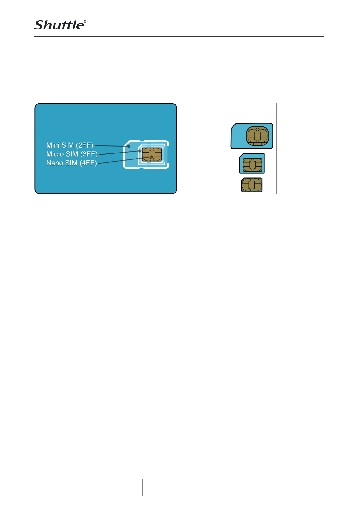
Compatible SIM cards
The SIM card is used to identify your mobile phone in a mobile network. SIM cards have been
shrinked over the years: The Mini standard has been superseded by Micro and Nano. The Shuttle
XPC accessory WWN03 only supports Nano format. A new SIM card usually comes perforated in three
sizes (Mini, Micro and Nano) and simply requires the desired format to be pressed out .
SIM format
Image
Supported by
WWN03?
Mini SIM
25 x 15 mm
No
Micro SIM
15 x 12 mm
No
Nano SIM
12.3 x 8.8 mm
Yes
Page 3

Product Specifications
w w w . s h u t t l e . e u
Shuttle C o m p u t e r H a n d e l s G m b H
Fr it z- St ras sma nn-S tr . 5
25 337 El msh or n | Ge r ma n y
Te l. +4 9 ( 0 ) 412 1 -4 7 6 8 6 0
Fa x + 4 9 ( 0) 41 21- 47 69 00
sa les @sh ut tle .eu
Page 3 2 1 N ovember 20 19
© 2019 by Shuttle Computer Handels GmbH (Germany). All information subject to change without notice
. Pictures for illustration purposes only.
Quick Guide to install the Accessory WWN03 into the XPC DS01U
Due to safety reasons, please turn off your computer completely first
and unplug it from the power supply.
(1) Unscrew the two screws of the chassis
cover. Slide the cover backwards and
upwards.
(2) Unfasten the rack mount screw and
remove the rack, then unscrew the ten
screws of the middle frame and remove it.
(3) Use a 6mm screwdriver to puncture the
perforated hole in the middle frame from
the outside in. Once the screwdriver passes
through the perforation, carefully remove
the metal tag.
Caution: If the metal tag still does not
detach, carefully bend it by pushing down
from the inside of the middle frame.
Page 4

Product Specifications
w w w . s h u t t l e . e u
Shuttle C o m p u t e r H a n d e l s G m b H
Fr it z- St ras sma nn-S tr . 5
25 337 El msh or n | Ge r ma n y
Te l. +4 9 ( 0 ) 412 1 -4 7 6 8 6 0
Fa x + 4 9 ( 0) 41 21- 47 69 00
sa les @sh ut tle .eu
Page 4 2 1 N ovember 20 19
© 2019 by Shuttle Computer Handels GmbH (Germany). All information subject to change without notice
. Pictures for illustration purposes only.
(4) Take out the two antenna cable
connectors and remove the locks and
protective sleeves.
(5) Then install the antenna cable
connectors through the appropriate
opening in the middle frame and use the
lock to affix the antenna from the outside.
Caution: When leading the cable
connector through the opening, check the
socket alignment and only push
horizontally. DO NOT turn or twist the cable.
Should any difficulties occur, make sure
the surface is clean. Finally, check the
alignment again and carefully apply more
force.
(6) Replace the middle frame, then fasten
the ten screws. As shown, place the
daughterboard (LN006) in the chassis and
fasten the three screws.
(7) Then connect the USB cable.
Page 5

Product Specifications
w w w . s h u t t l e . e u
Shuttle C o m p u t e r H a n d e l s G m b H
Fr it z- St ras sma nn-S tr . 5
25 337 El msh or n | Ge r ma n y
Te l. +4 9 ( 0 ) 412 1 -4 7 6 8 6 0
Fa x + 4 9 ( 0) 41 21- 47 69 00
sa les @sh ut tle .eu
Page 5 2 1 N ovember 20 19
© 2019 by Shuttle Computer Handels GmbH (Germany). All information subject to change without notice
. Pictures for illustration purposes only.
(8) Please install an LTE module (M.2-3042
Key B card) in the relevant slot on the
daughterboard, then tighten the screw with
bolt firmly.
(9) As shown, connect the two antenna
cables to "MAIN" and "AUX" on your LTE
module.
(10) Note: If the DS10U is operated in
vertical position with the stand, you cannot
install an antenna at the bottom side. This
means only 3 antennas can be used for
WLAN and LTE in total (either LTE or WLAN
will have to work with one antenna only).
LTE
WLAN
WLAN
(11) Replace the case cover and fasten its
screws.
Screw the antennas into position as
pictured. Make sure they are aligned
vertically to achieve the best possible
signal reception.
 Loading...