

Page 1

FB81
Pentium 4, LGA 775 Processor
Based MAIN BOARD
Page 2

Shuttle® FB81
Pentium 4, LGA 775 Processor Based Mainboard
Copyright
Copyright© 2004 by Shuttle® Inc. All Rights Reserved.
No part of this publication may be reproduced, transcribed, stored in a retrieval system,
translated into any language, or transmitted in any form or by any means, electronic,
mechanical, magnetic, optical, chemical, photocopying, manual, or otherwise, without
prior written permission from Shuttle® Inc.
Disclaimer
Shuttle® Inc. shall not be liable for any incidental or consequential damages resulting from the
performance or use of this product.
This company makes no representations or warranties regarding the contents of this manual.
Information in this manual has been carefully checked for reliability; however, no guarantee is
given as to the correctness of the contents. In the interest of continued product improvement,
this company reserves the right to revise the manual or include changes in the specifications
of the product described within it at any time without notice and without obligation to notify any
person of such revision or changes. The information contained in this manual is provided for
general use by the customers.
Trademarks
Shuttle is a registered trademark of Shuttle Inc.
Intel, Pentium is a registered trademarks of Intel Corporation.
PS/2 is a registered trademark of IBM Corporation.
AWARD is a registered trademark of Award Software Inc.
Microsoft and Windows are registered trademarks of Microsoft Corporation.
General Notice: Other product names used in this manual are ascribed to their respective
owners and acknowledged.
MA25
Page 3

Statement of Shuttle Mainboard via the EMI Test
Shuttle mainboards have been via the EMI test in terms of series of regulations: EN55022/
CISPR22/AS/NZS3548 Class B, EN55024 (1998/AS/NZS), EN4252.1 (1994), EN61000, ANSI
C63.4 (1992), CFR47 Part 15 Subpart B, and CNS13438 (1997). The items tested are illustrated as follows:
(A) Voltage: AC 110V/60HZ & AC 230V/50HZ
(B) Tested Product Information:
Product Name: PC Mainboard
Status: Sample
Model Name: FB81
S/N: N/A
CPU:
External Frequency: 133 MHz
Intel Pentium 4, LGA 775 Processor: 2.8 GHz
External Frequency: 200 MHz
Intel Pentium 4, LGA 775 Processor: 2.8/ 3/ 3.2/ 3.4/ 3.6 GHz
Serial Port: one port with 9 pins
VGA Port: one port with 15 pins
Keyboard Port: one port with 6 pins
Mouse Port: one port with 6 pins
USB 2.0 Port: four ports with 4 pins respectively
1394 Port: two ports with 6 pins respectively
LAN Port: one port with 8 pins (10Mbps/100Mbps/1000Mbps)
Center/Bass-Out Port: one port
Line-In Port: one port
Mic Port: one port (The function is based on front panel.)
Front-Out Port: one port
Surround-Back Port: one port
Rear-Out Port: one port
SPDIF-Out (Coaxial) Port: one port
SPDIF-Out (Optical) Port: one port
SPDIF-In (Optical) Port: one port
Clear CMOS button: one port
DIMM Memory (optional): DDR 400 256 MB *2
Power Cable: Detachable and Shielded (with a GND pin)
Monitor: CRT
Maximum Resolution: 1280 X 1024 V:60Hz
All CPUs have completely been tested, and values offered by the worst EMI combination of
CPU external frequency are listed as follows:
Test Mode External Frequency CPU CPU Open/Close
1 200MHz P4 3.6 GHz Close
2 200MHz P4 3.6 GHz Open
3 133MHz P4 2.8 GHz Close
4 133MHz P4 2.8 GHz Open
Page 4

(C) Remedy for the Tested Product & Its EMI Interference:
Remedy: N/A
EMI Interference:
Crystal: 14.318MHz(X2)/ 25.00MHz(X3)/ 24.576MHz(X4)/ 32.768KHz(X1)
Clock Generator: U5
(D) Supported Host Peripherals:
Host Peripheral Product Name Model Name
# 1 Case FB81
# 2 Power Supply PC43I3503
# 3 Serial ATA Westerm Digital WD1200JD-00FYB0
# 4 Shuttle Card Reader A011
# 5 Pioneer DVD Player DVD-116
(E) Notices for Assembling Computers:
1. Cases should be made of iron or other metal that has good electric conductivity.
2. Cylinders in a case should be made of metal, and as having a mainboard mounted
in a case, make sure screws are all utilized and fastened on a mainboard.
3. An I/O shielding should be contacted with I/O metallic parts of a mainboard.
4. Cables should appropriately be arranged and fixed in a case. Follow instructions:
Ø Leave IDE cables not crossed upon CPU and SDRAM;
Ø Leave power cables minimum in length, and not crossed upon a mainboard;
Ø Leave CPU fan cables minimum in length, and not near CPU;
Ø Leave cables on panels and other spare cables tied in a computer case.
5. Make sure an EMI shielding attached to a case has properly been installed.
6. Make sure a 5.25" and screws are fastened to an EMI shielding.
7. Make sure a case is closely in contact with EMI connected points.
8. Make sure there is no cleft in a case which is not deformed.
9. Make sure a PCI door is bound to a case.
10. Make sure cables of other devices (fans or some others) are fixed in a case.
Page 5

Important Safety Information
SAFETY INSTRUCTIONS
1. Please read these safety instructions carefully.
2. Please keep this User‘s Manual for later reference.
3. Please disconnect this equipment from AC outlet before cleaning. Don‘t use liquid
or sprayed detergent for cleaning.
4. For pluggable equipment, the socket-outlet shall be installed near the equipment
and shall be easily accessible.
5. Please keep this equipment from humidity.
6. Lay this equipment on a reliable surface when install. A drop or fall could cause injury.
7. Do not leave this equipment in an environment unconditioned, it may damage the
equipment.
8. The openings on the enclosure are for air convection hence Protect the equipment
from overheating. DO NOT COVER THE OPENINGS.
9. Make sure the voltage of the power source when connect the equipment to the
power outlet.
10. Place the power cord such a way that people can not step on it. Do not place anything
over the power cord. The power cord must be rated for the product and for the voltage
and current marked on the product’s electrical ratings label. The voltage and current
rating of the cord should be greater than the voltage and current rating marked on the
product.
11. All cautions and warnings on the equipment should be noted.
12. If the equipment is not use for long time, disconnect the equipment from mains to avoid
being damaged by transient over-voltage.
13. Never pour any liquid into ventilation openings, this could cause fire or electrical shock.
14. CAUTION: The computer is provided with a battery-powered real-time clock circuit.
There is a danger of explosion if battery is incorrectly replaced.
Replace only with same or equivalent type recommended by the manufacture.
Discard used batteries according to the manufacturer’s instructions.
CAUTION : RISK OF EXPLOSION IF BATTERY IS REPLACED BY AN
INCORRECT TYPE. DISPOSE OF USED BATTERIES
ACCORDING TO THE INSTRUCTIONS
15. THE COMPUTER IS PROVIDED WITH CD DRIVES COMPLY WITH APPROPRIATE SAFETY STANDARDS INCLUDING IEC 60825.
CLASS 1 LASER PRODUCT
Page 6

TABLE OF CONTENTS
WHAT'S IN THE MANUAL....................................................................5
Quick Reference............................................................................................... 5
About This Manual ........................................................................................... 5
1 INTRODUCTION ................................................................................ 6
1.1 TO DIFFERENT USERS ............................................................................. 6
FIRST-TIME DIY SYSTEM BUILDER............................................................ 6
EXPERIENCED DIY USER ........................................................................ 6
SYSTEM INTEGRATOR............................................................................... 6
1.2 ITEM CHECKLIST....................................................................................... 7
2 FEATURES ........................................................................................ 8
2.1 SPECIFICATIONS ....................................................................................... 8
3 HARDWARE INSTALLATION.......................................................... 11
3.1 STEP BY STEP INSTALLATION................................................................11
Accessories of FB81..............................................................................11
STEP 1 CPU Installation........................................................................ 12
STEP 2 Set Jumper............................................................................... 14
STEP 3 Install DDR SDRAM System Memory........................................ 14
STEP 4 Install Internal Peripherals in System Case ................................ 15
STEP 5 Mount the Mainboard on the Computer Chassis........................ 16
STEP 6 Connect Front-Panel Switches/LEDs/USBs/1394/Headphones
/Front-Mic................................................................................. 16
STEP 7 Connect IDE, Floppy and Serial ATA Disk Drives...................... 17
STEP 8 Connect Other Internal Peripherals............................................ 18
STEP 9 Install Add-on Cards in Expansion Slots .................................... 20
STEP 10 Connect Power Supply ........................................................... 20
STEP 11 Connect External Peripherals to Back-panel ........................... 21
STEP 12 First Time System Boot Up..................................................... 22
- 1 -
Page 7

STEP 13 Install Driver & Software Components..................................... 23
3.2 JUMPER SETTINGS ................................................................................. 24
JUMPERS & CONNECTORS GUIDE.................................................... 25
Back-Panel Connectors
VGA Port............................................................................................... 28
COM Port .............................................................................................. 28
Clear CMOS Button............................................................................... 28
1394 Port .............................................................................................. 28
PS/2 Keyboard & PS/2 Mouse Ports ..................................................... 28
Giga LAN Port....................................................................................... 29
USB Ports ............................................................................................. 29
SPDIF-Out Coaxial Port......................................................................... 29
SPDIF-Out Optical Port ......................................................................... 29
SPDIF-In Optical Port ............................................................................ 29
7.1 Channel Rear-Out Port..................................................................... 30
7.1 Channel Bass/Center Port ............................................................... 30
7.1 Channel Front-Out Port .................................................................... 30
7.1 Channel Surround-Back Port............................................................ 30
Line-In Port ............................................................................................ 30
Front-Panel Connectors
FRONT PANEL Connectors (JP6/JP3) .................................................. 31
Internal Peripherals Connectors
Enhanced IDE, Floppy Connectors ........................................................ 32
Serial ATA Connectors........................................................................... 32
Other Connectors
Power Connectors (8-pin ATX2, 6-pin ATX1, 4-pin ATX3)....................... 33
Fan Connectors - FAN1/2/3/4 ................................................................ 34
- 2 -
Page 8

CD-IN/Mini CD-IN Connectors (CN3)(Black) / (CN4)(White) ................... 34
AUX-IN Connector (CN2) (White)........................................................... 35
Extended USB Connector (USB2) ......................................................... 35
Parallel Port Header- EXT. Print Port (JP5)............................................ 36
EXT. GPI Header (JP1).......................................................................... 36
3.3 SYSTEM MEMORY CONFIGURATION ..................................................... 37
INSTALL MEMORY................................................................................ 37
UPGRADE MEMORY............................................................................ 37
4 SOFTWARE UTILITY ......................................................................38
4.1 Mainboard CD Overview ......................................................................... 38
4.2 Install Mainboard Software ..................................................................... 39
4.2.A Install Intel Chipset Driver ................................................................... 40
4.2.B Install Intel VGA Driver......................................................................... 40
4.2.C Install Intel IAA Driver.......................................................................... 41
4.2.D Install Broadcom Giga LAN Driver...................................................... 41
4.2.E Install Broadcom BACS....................................................................... 42
4.2.F Install Intel USB 2.0 Driver................................................................... 42
4.2.G Install Intel High Definition Bus .......................................................... 43
4.2.H Install Intel High Definition Audio Driver ............................................ 43
4.2.I Install DirectX9 Utility........................................................................... 44
4.3 View the User's Manual........................................................................... 45
5 BIOS SETUP ...................................................................................46
5.1 Enter the BIOS .......................................................................................... 46
5.2 THE MAIN MENU ...................................................................................... 47
STANDARD CMOS FEATURES ............................................................... 49
ADVANCED BIOS FEATURES................................................................. 52
ADVANCED CHIPSET FEATURES .......................................................... 57
INTEGRATED PERIPHERALS .................................................................. 59
- 3 -
Page 9

POWER MANAGEMENT SETUP.............................................................. 64
PNP/PCI CONFIGURATIONS .................................................................... 68
PC HEALTH STATUS................................................................................ 70
FREQUENCY/VOLTAGE CONTROL......................................................... 72
LOAD FAIL-SAFE DEFAULTS .................................................................. 75
LOAD OPTIMIZED DEFAULTS ................................................................. 75
SET PASSWORD ..................................................................................... 75
SAVE & EXIT SETUP................................................................................ 76
EXIT WITHOUT SAVING ............................................................................ 76
- 4 -
Page 10

WHAT'S IN THE MANUAL
Quick Reference
Hardware Installation >> Step-by-Step ................................................ Page 11
Jumper Settings >> A Closer Look.......................................................Page 24
Drivers/Software Utilities >> How to Install .........................................Page 38
BIOS Setup >> How to Configure.........................................................Page 46
About This Manual
For First-Time DIY System Builder.........................................................Page 6
For Experienced DIY User ......................................................................Page 6
For System Integrator .............................................................................Page 6
- 5 -
Page 11

1 INTRODUCTION
1.1 To Different Users
First-Time DIY System Builder
Welcome to the DIY world! Building your own computer system is not as difficult as you may think. To make your first computer DIY experience successful,
right from the start, we have designed the 3.1 Hardware Installation section
in a step-by-step fashion for all the first-time DIY system builders. Prior to installation, we also suggest you to read the whole manual carefully to gain a complete understanding of your new Shuttle FB81 mainboard.
Experienced DIY User
Congratulate on your purchase of the Shuttle FB81 mainboard. You will find
that installing your new Shuttle FB81 mainboard is just easy. Bundled with an
array of onboard functions, the highly-integrated FB81 mainboard provides you
with a total solution to build the most stable and reliable system. Refer to sections 3.2 Jumper Settings and Chapter 4 Drivers/Software Utilities to
find out how to get the best out of your new mainboard. Chapter 5 BIOS
Setup also contains the relevant information on how to tune up your system to
achieve higher performance.
System Integrator
You have wisely chosen Shuttle FB81 to construct your system. Shuttle FB81
incorporates all the state-of-the-art technology of the Grantsdale-G + ICH6R
chipset from Intel. It integrates the most advanced functions you can find to
date in a compact Small Form Factor board.
- 6 -
Page 12

1.2 Item Checklist
VSO
111
ATX1
1
USB2
F
A
N
4
F
A
N
1
3465604
SEP
C
3465604
SEP
C
3465604
SEP
C
3465604
SEP
C
3465604
SEP
C
3465604
SEP
C
3465604
SEP
C
3465604
SEP
C
FDD1
VT63070352CD TAIWAN2HA100B4
3
JP3
ATX31CN4
CN1
SW1
KB1
Check all items with your FB81 mainboard to make sure nothing is missing.
The complete package should include:
- One piece of Shuttle FB81 Mainboard
- One piece of ATA100/66/33 Ribbon Cable
- One piece of Floppy Ribbon Cable
CN5
1
1
OPT1
AUDIO
USB1
IDE1
DIMM1
DIMM2
1
FAN2
JP6
JP1
JP5
ATX2
CN3
CN2
FAN3
SATA3
SATA4
SATA1
SATA2
ADD2
PCI1
1
- One piece of Serial ATA Cable
- FB81 User's Manual
- ICH6R RAID Manual
- One piece of Bundled CD-ROM with containing:
Ø FB81 user's manual saved in PDF format
Ø Install Intel Chipset Driver
Ø Install Intel VGA Driver
Ø Install Intel IAA Driver
Ø Install Broadcom Giga LAN Driver
Ø Install Broadcom BACS
Ø Install Intel USB 2.0 Driver
Ø Install Intel High Definition Bus
Ø Install Intel High Definition Audio Driver
Ø Install DirectX9 Utility
Ø Award Flashing Utility
SERIAL
ATA
- 7 -
Page 13

2 FEATURES
FB81 mainboard is carefully designed for the demanding PC user who wants high performance and maximum intelligent features in a compact package.
2.1 Specifications
- CPU Support
Intel Pentium 4 Desktop Processors in the LGA 775 pin package with 533 /
800 MHz FSB.
- Chipset
Features Intel Grantsdale-G N.B. and ICH6R S.B..
Onboard Lan
BCM5751 PCI-E Lan Chipset support 10/100/1000 Mbps operation rate and
wake-on-Lan (WOL) function.
Onboard 1394
VIA VT6307, support 400Mb/s, 200Mb/s, or100Mb/s data transfer rate.
- Jumperless CPU Configuration
Soft-configuration FSB (The FSB speed is software configurable from 100 MHz
to 355 MHz of BIOS setup program.)
- OnBoard High Definition Audio CODEC (7.1-CHANNEL)
Realtek ALC880 include 96 KHz SPDIF-IN/OUT function and 8 channels of
DAC support 16 / 20 / 24-bit PCM format for 7.1 audio solution compliant with
Intel High Definition specification. 8 jacks (Front, Surr, Cen/LFE, Surrback, Line1,
Line2, Mic1 and Mic2) are stereo input and output re-tasking for analog Plug &
Play (PnP) and support CD-in & AUX-in connectors.
- Versatile Memory Support
Features the dual-channel mode of 128 bit data transfer rate.
Two 184-pin DIMM slots to support up to 4GB of PC2700 or PC3200
compliant unbuffered without ECC DDR SDRAM module.
- PCI Expansion Slot
Provides one 32-bit PCI slot.
- PCI Express Graphics (PEG) & SDVO Interface Slot
The X16 port operates at a frequency of 2.5 Gb/s while employing 8b / 10b
encoding. Supports Analog / Digital display & TMDS transmitters or TV-OUT
encoders via an Advance Digital Display (ADD2) card.
- 8 -
Page 14

- USB 1.1/2.0 Complaint Interface Onboard
Ø 4 UHCI USB 1.1 Host controller and 1 EHCI USB 2.0 Host controller
support up to 8 USB ports. All 8 USB ports can be assigned to USB 2.0
interface with BIOS option
- I/O Interface
Provides a variety of I/O interfaces:
Ø 1 x DB9 Serial port.
Ø 1 x DB15 VGA connector.
Ø 1 x Clear CMOS button.
Ø 1 x 1394 port.
Ø 1 x PS/2 Mouse port.
Ø 1 x PS/2 Keyboard port.
Ø 1 x Giga LAN port.
Ø 2 x USB 1.1/2.0 ports.
Ø 1 x SPDIF-Out Coaxial port.
Ø 1 x SPDIF-Out Optical port.
Ø 1 x SPDIF-In Optical port.
Ø 1 x 7.1 Channel Rear-Out port.
Ø 1 x 7.1 Channel Bass/Center port.
Ø 1 x 7.1 Channel Front-Out port.
Ø 1 x 7.1 Channel Surround-Back port.
Ø 1 x Line-In port.
- PCI Bus Master IDE Controller Onboard
One Ultra DMA 100/66/33 Bus Master Dual-channel IDE ports provide support to a maximum of two IDE devices (one Master and one Slave per channel).
The IDE Bus implements data transfer speeds of up to 100/66/33 MB/sec and
also supports Enhanced PIO Modes. 80-pin Cable Backward Compatible Legacy
ATAPI Devices, ATAPI IDE CD-ROM, CD-R, CD-RW, and LS-120 supports.
- Advanced Configuration and Power Interface
Features four power saving modes: S1 (Snoop), S3 (Suspend to RAM), S4 (Suspend to DISK), and S5 (Soft-Off). ACPI provides more efficient Energy Saving
Features controlled by your operating system that supports OS Direct Power
Management (OSPM) functionality.
- 9 -
Page 15

- System BIOS
Provides licensed Award BIOS V6.0 PG on 4Mb Flash core and supports Green
PC, Desktop Management Interface (DMI).
- Form Factor
System board conforms to Shuttle small form factor specification.
Board dimension: 280mm x 205mm.
- Advanced Features
Ø Low EMI - Built in spread spectrum to reduce EMI.
Ø Dual Function Power Button - The system can be in one of two states,
one is Suspend mode and the other is Soft-Off mode. Pushing the power
button for less than 4 seconds places the system into Suspend mode.
When the power button is pressed for longer than 4 seconds, the system
enters Soft-Off mode.
Ø Modem Ring Power-On - The system can be powered on automatically
by the activation of modem ringing.
- Intelligent Features
Ø Voltage Monitoring -
Monitors various voltages of key elements, such as the CPU, and other critical system voltage levels to ensure stable current passing through mainboard
components.
Ø Fan Status Monitoring -
To prevent CPU from overheating, the CPU fan is monitored for RPM and
failure. (CPU Cooling FAN with RPM sensor is required.)
Ø Temperature Monitoring -
This item allows users to make sure whether the CPU or system runs in a
suitable temperature.
Ø CPU Fan AutoGuardian -
This SMART Bios enabled multi-phase Variable Fan Speed and CPU temperature Control feature.
- 10 -
Page 16

3 HARDWARE INSTALLATION
111
ATX1
1
F
A
N
4
F
A
N
1
F
A
N
2
3465604
SEP
C
3465604
SEP
C
3465604
SEP
C
3465604
SEP
C
3465604
SEP
C
3465604
SEP
C
3465604
SEP
C
3465604
SEP
C
FDD1
S
A
T
A
3
S
A
T
A
4
I
1
JP3
ATX31CN4
CN1
SW1
KB1
1394 Port
EXT. Print Port- JP5
USB Header
CD-IN- CN3
FAN Connector
Front Panel Connector- JP6
Front Panel Connector- JP3
Before removing or installing any of these devices including CPU, DIMMs,
Add-On Cards, Cables, please make sure to unplug the onboard power
connector.
This section outlines how to install and configure your mainboard. Refer to the following
mainboard layout to help you to identify various jumpers, connectors, slots, and ports. Then
follow these steps designed to guide you through a quick and correct installation of your
system.
3.1 Step-by-Step Installation
Accessories Of FB81
PS/2 Keyboard/Mouse s Port
Giga LAN & USB 2.0 s Port
SPDIF-OUT Coaxial/Optical Ports
SPDIF-IN/Rear-Out/
Center/Bass/Front-Out/
Surround-Back/Line-In
Ports
AUDIO
Realtek ALC880
OPT1
USB1
CN5
ATX2
1
JP5
CN3
CN2
Clear CMOS Button
Power Connector- ATX2
COM & PortsVGA
FAN Connector- FAN3
1
USB2
- USB2
Mini CD-IN- CN4
BCM5751 Lan Chipset
One IDE Connector
IDE1
DIMM1
DIMM2
1
FAN3
SATA1
SATA2
ADD 2
AUX-IN- CN2
Four Serial ATA
Connectors
ICH6R (82801FR)
Chipset
PC
1
Intel Grantsdale-G
(915G) Chipset
TWO 184-pin DDR
One PCI Slot
One PEG Slot
One Floppy
Connector
ATX 5V/12V
Connector-ATX3
- FAN4, FAN1
SDRAM DIMM Sockets
LGA 775 Pin Package
CPU Socket
FAN Connector- FAN2
EXT.GPI Header- JP1
Power Connector
JP1
JP6
- ATX1
- 11 -
Page 17

Step 1
CPU Installation
This motherboard supports LGA 775 package Processors (CPU).
To install, follow the steps outlined below. Note the CPU orientation carefully
when you insert it into the socket.
Caution : This 775 pin socket is fragile and easily damaged.
Always use extreme care when installing a CPU and limit the
number of times that you remove or change the CPU.
1. Remove the protective cover.
2. Unlock and raise the socket lever. Open the load plate (be careful not to
touch the socket pins during this process).
3
1
2
- 12 -
Page 18

3. Orientate the CPU and socket, aligning the yellow triangle on the corner of
the CPU with the triangle on the socket. Gently insert. Take care not to place
any sideways force on the CPU when inserting, as the socket is fragile and
easily damaged.
Pentium 4, LGA 775 Processor
Triangle Markings
4. Lower the CPU socket lever and lock in place.
Note : The CPU might be damaged
if you do not match the CPU
socket Pin 1 and cut edge well.
Lever
5. The LGA 775 package processor requires a heat sink and cooling fan to run
efficiently, cool and stable. If you do not receive a bundled heat sink and fan
when you purchase you CPU, it is essential that you acquire one.
- 13 -
Page 19
Step 2
VDIMM
Set Jumper
This mainboard is jumperless! The default jumper settings have been set for the
common usage standard of this mainboard. Therefore, you do not need to reset
the jumpers unless you require special adjustments as any of the following cases:
1. Clear CMOS
For first-time DIY system builders, we recommend that you do not change the
default jumper settings if you are not totally familiar with the mainboard configuration procedures. The factory-set default settings are tuned for optimum
system performance. For the advanced users who wish to customize their system, section 3.2 Jumper Settings will provide detailed information on how to
configure your mainboard manually.
Caution: If you did not place the battery apropriately, which may cause
risk of explosion. Please pefer to the related rule for the dispose of used batteries.
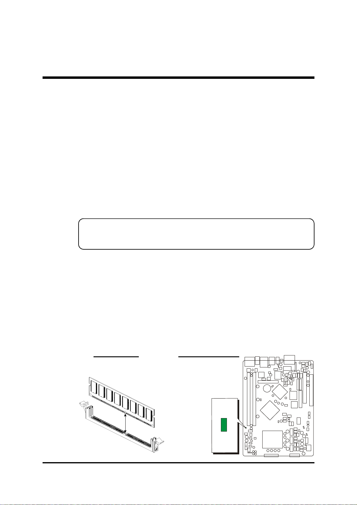
Step 3
Install DDR SDRAM System Memory
To install memory, insert DDR SDRAM memory module(s) in DIMM slot(s).
Note that DDR SDRAM modules are directional and will not go in the DIMM
slots unless properly oriented. After the module is fully inserted into the DIMM
slots, lift the clips of both sides of the DIMM slot to lock the module in place.
Do not remove memory modules while DIMM LED is on. It might cause short
or other unexpected damages due to the 2.6V stand by voltage. Remove memory
modules only when AC Power cord is disconnected.
DDR SDRAM DIMM Power LED
LED
LED1
(Green)
- 14 -
Page 20

Step 4
Install Internal Peripherals in System Case
Before you install and connect the mainboard into your system case, we recommend that you first assemble all the internal peripheral devices into the computer housing, including but not limited to the hard disk drive (IDE/HDD), floppy
disk drive (FDD), CD-ROM drive, and power supply unit. This will greatly facilitate in making the connections to the mainboard described below.
To install IDE & FDD drives, follow this procedure:
1. Set the required jumpers on each device according to the instructions pro-
vided by the manufacturer. (IDE devices, HDD, and CD-ROM, have to set
jumpers to Master or Slave mode depending on whether you install more
than one device of each kind.)
2. Connect IDE cable and FDD cable on the back-panel of the internal periph-
eral devices to the corresponding headers on board. Note that the cable
should be oriented with its colored stripe (usually red or magenta) connected
to pin#1 both on the mainboard IDE or FDD connector and on the device as
well.
3. Connect an available power cable from your system power supply unit to
the back-panel of each peripheral device. Note that the power cable is directional and cannot fit in if not properly positioned.
- 15 -
Page 21

Step 5
JP3
Mount the Mainboard on the Computer Chassis
1.
You may find that there are a lot of different mounting hole positions both on your computer chassis
and on the mainboard. To choose correct mounting holes, the key point is to keep the backpanel of
the mainboard in a close fit with your system
case.
2.
After deciding on the proper mounting holes, position the studs between the frame of the chassis
and the mainboard. The studs are used to fix the
mainboard and to keep a certain distance between
the system's chassis and the mainboard, in order
to avoid any electrical shorts between the board
and the metal frame of the chassis.
(If your computer case is already equipped with mounting studs, you will
need to tighten screws to attach the mainboard.)
Note : In most computer housings, you will be able to find 4 or more
attachment points to install mounting studs and then fix the mainboard. If there aren't enough matching holes, then make sure to
install at least 4 mounting studs to ensure proper attachment of
the mainboard.
Step 6
Connect Front-Panel Switches/LEDs/
USBs/1394/Headphones/Front-Mic
You are now ready to put the computer
case back together and get on to the external peripherals connections to your
system's front-panel.
- 16 -
JP6
1
1
Page 22
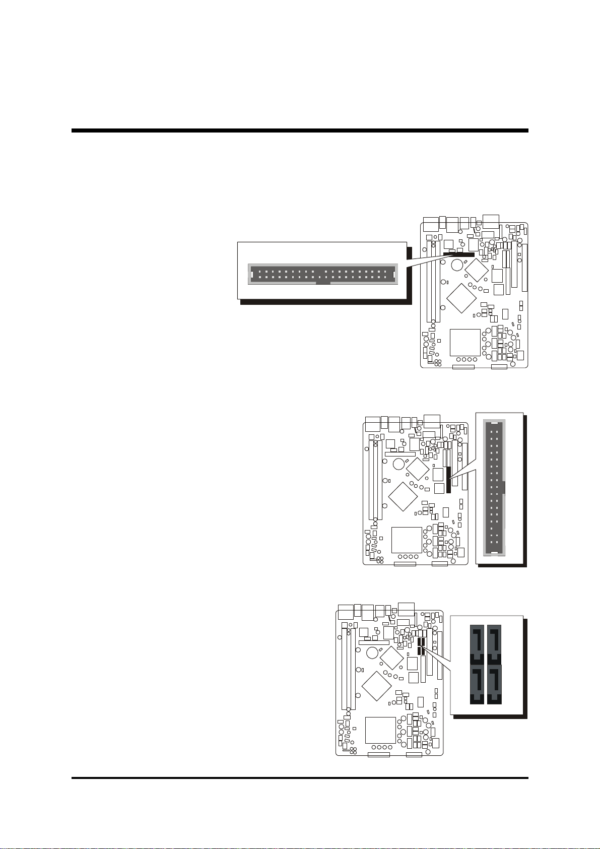
Step 7
S
A
T
A
2
S
A
T
A
4
S
A
T
A
1
S
A
T
A
3
1
1
Connect IDE, Floppy, and Serial ATA Disk Drives
1. IDE cable connector
1
IDE1
2. Floppy cable connector
3. Serial ATA connectors
FDD
- 17 -
Page 23
Step 8
1
CD-IN
CN4
CD-IN
AUX-IN
1
USB2
Connect Other Internal Peripherals
1. CD-IN Header (CN3)
AUX-IN Header (CN2)
Mini CD-IN Header (CN4)
2. USB Header (USB2)
1
Mini
CN3
CN2
1
- 18 -
Page 24
3. Parallel port Header (JP5)
1
JP5
EXT. Print Port
4. EXT. GPI Header (JP1)
EXT. GPI Header
1
JP1
- 19 -
Page 25
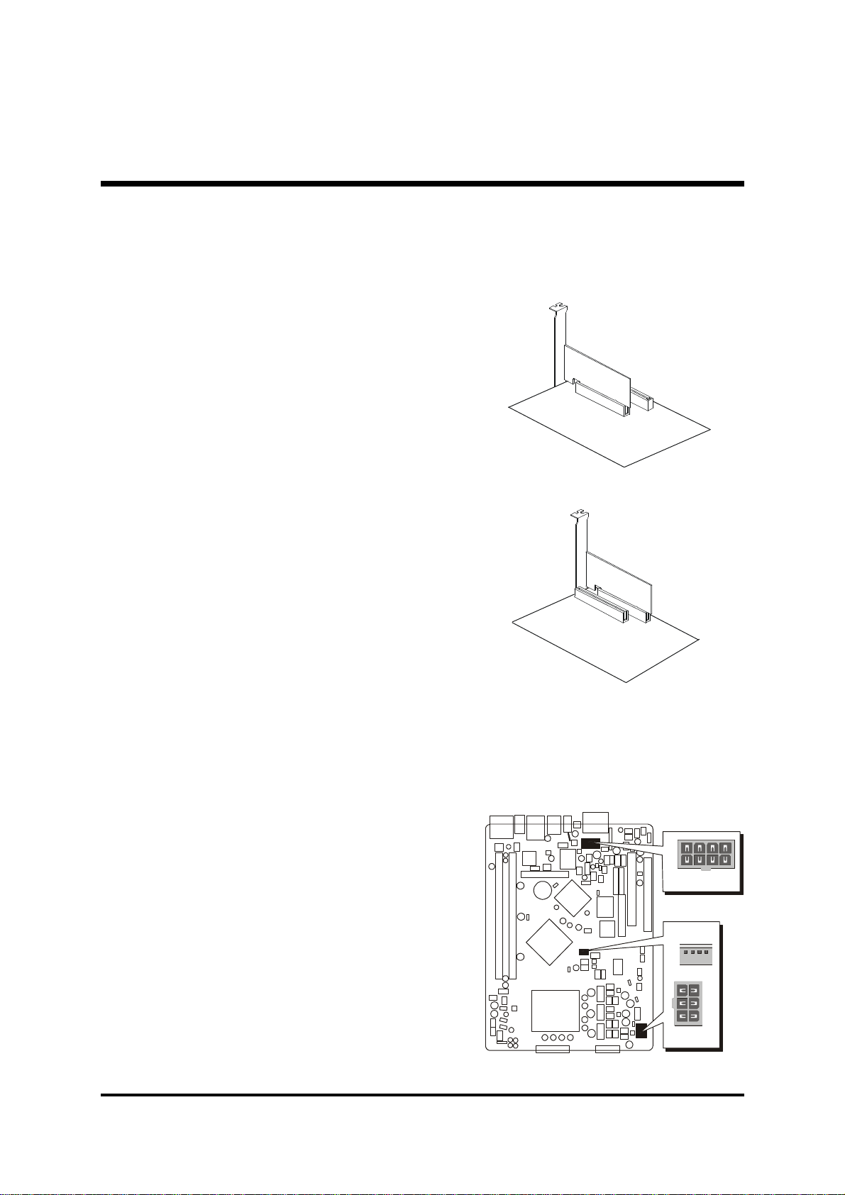
Step 9
1
ATX1
1
ATX2
ATX3
Install Add-on Cards in Expansion Slots
1. PCI Card
2. PCI Express Graphics (PEG)
& SDVO Interface Card
Step 10
Connect the Power Supply
1. System power connectors (ATX1/ATX2/ATX3)
- 20 -
1
Page 26

Step 11
857
9
Connect External Peripherals to Back-Panel
You are now ready to put the computer case back together and get on to the
external peripherals connections to your system's back-panel.
1. DB9 Serial port
2. DB15 VGA port
3. Clear CMOS button
4. 1394 port
5. PS/2 Mouse port
6. PS/2 Keyboard port
7. Giga LAN port
8. USB 1.1/2.0 ports
9. SPDIF-Out Coaxial port
10. SPDIF-Out Optical port
11. SPDIF-In Optical port
12. 7.1 Channel Rear-Out port
13. 7.1 Channel Bass/Center port
14. 7.1 Channel Front-Out port
15. 7.1 Channel Surround-Back port
16. Line-In port
1
2
3 4 6
- 21 -
Page 27

Step 12
First Time System Boot Up
To assure the completeness and correctness of your system installation, you
may check the above installation steps once again before you boot up your
system for the first time.
1. Insert a bootable system floppy disk (DOS 6.2x, Windows 95/98/NT, or
others) which contains FDISK and FORMAT utilities into the FDD.
2. Turn on the system power.
3. First, you must use the FDISK utility to create a primary partition of the hard
disk. You can also add an extended partition if your primary partition does
not use all of the available hard disk space. If you choose to add an extended partition, you will have to create one or more logical partitions to
occupy all the space available to the extended partition. The FDISK utility
will assign a drive letter (i.e., C:, D:, E:,...) to each partition which will be
shown in the FDISK program. After FDISK procedure, reboot your system
by using the same system floppy disk.
Note : DOS 6.2x and Windows 95A can only support up to 2.1GB of
HDD partition. If you use the FDISK utility with one of the operat-
ing systems mentioned above, you can only install your HDD
into partitions no larger than 2.1GB each.
4. Now, use the FORMAT utility to format all the partitions you’ve created.
When formatting the primary partition (C:), make sure to use the FORMAT C: /S command.
Note : FORMAT C: /S can transfer all the necessary system files into the
primary partition of your hard disk. Then, your HDD will become
a bootable drive.
5. Install all the necessary drivers for CD-ROM, Mouse, etc.
6. Setup the complete operating system according to your OS installation
guide.
- 22 -
Page 28

Step 13
Install Drivers & Software Components
Please note that all the system utilities and drivers are designed for Win 2000/
XP operating systems only. Make sure your operating system is already installed
before running the drivers installation CD-ROM programs.
1. Insert the FB81 bundled CD-ROM into your CD-ROM drive. The autorun
program will display the drivers main installation window on
screen.
2. Choose "Install Intel Chipset Driver" and complete it.
3. Choose "Install Intel VGA Driver" and complete it.
4. Choose "Install Intel IAA Driver" and complete it.
5. Choose "Install Broadcom Giga LAN Driver" and complete it.
6. Choose "Install Broadcom BACS" and complete it.
7. Choose "Install Intel USB 2.0 Driver" and complete it.
8. Choose "Install Intel High Definition Bus" and complete it.
9. Choose "Install Intel High Definition Audio Driver" and complete it.
10. Choose "Install DirectX9 Utility" and complete it.
] Please refer to section Chapter 4 Software Utility to install driver.
- 23 -
Page 29

3.2 Jumper Settings
Several hardware settings are made through the use of jumper caps to connect
jumper pins to the mainboard. Pin #1 could be located at any corner of each
jumper; you just find a location marked with a while right angle, which stands
for pin1#. There are several types of pin 1# shown as below:
3-pin and multi-pin (>3) jumpers show as follows:
Pin #1 to the left:
Pin #1 on the top:
Pin #1 to the right:
Pin #1 on the bottom:
Jumpers with two pins are shown as for Close [On] or for Open
[Off]. To Short jumper pins, simply place a plastic jumper cap over the desired
pair of pins.
1
1
Caution!
1. Do not remove the mainboard from its antistatic protective packaging
until you are ready to install it.
2. Carefully hold the mainboard by its edges and avoid touching its
components. When putting the mainboard down, place it on the top
of its original packaging film and on an even surface, and components
side up.
3. Wear an antistatic wrist strap or take other suitable measures to prevent
electrostatic discharge (ESD) whenever handling this equipment.
- 24 -
Page 30

Jumpers & Connectors Guide
A1~A2
B1
C2
C1C1D1D2D2
D7
D2D4D3
D1
Use the mainboard layout on page 11 to locate CPU socket, memory banks,
expansion slots, jumpers and connectors on the mainboard during the installation. The following list will help you to identify jumpers, slots, and connectors
along with their assigned functions:
A8~A9
A6~A7
A5
A3A4
D6
D1 D5
- 25 -
Page 31

CPU/Memory/Expansion Slots
LGA 775 : CPU Socket for Pentium 4 LGA 775 processors
DIMM1/2 : Two 184-pin DIMM Slots for 128, 256, 512 MB, 1GB,
and 2GB of 2.6V DDR SDRAM
(The total installed memory does not exceed 4GB)
PCI : One 32-bit PCI Expansion Slot
PEG : One 16-Lane PCI Express port for Graphic Attach
Back Panel Connectors
A1
A2
A3
A4
A5
A5
A6
A7
A8
A9
A10
A11
A12
A13
A14
A15
VGA : VGA Port (DB15 female)
COM : Serial Port (DB9 male)
Clear CMOS : Clear CMOS button
1394 : 1394 Port
MS : PS/2 mouse Port
KB : PS/2 keyboard Port
Giga LAN : Giga LAN Port
USB : 2 USB 2.0/1.1 Ports
SPDIF-OUT Coaxial : SPDIF-OUT Coaxial Port
SPDIF-OUT Optical : SPDIF-OUT Optical Port
SPDIF-IN Optical : SPDIF-IN Optical Port
Rear-OUT : 7.1-Channel Rear-Out Port
Bass/Center : 7.1-Channel Bass/Center Port
Front-OUT : 7.1-Channel Front-Out Port
Surround-Back : 7.1-Channel Surround-Back Port
Line-IN : Line-In Port
Front Panel Connectors
B1
JP6/JP3 : Front Panel Connectors
Internal Peripherals Connectors
C1
C1
C2
FDD : Floppy disk drive interface
IDE1 : IDE primary interface (Dual-channel)
SATA1/2/3/4 : Serial ATA Connectors
- 26 -
Page 32

Other Connectors
D1
D2
D3
D4
D5
D6
D7
ATX1/2/3 : Power Connectors
(8-pin ATX2, 6-pin ATX1, 4-pin ATX3)
FAN1/2/3/4 : Fan Connectors
CN3/4 : CD-IN/Mini CD-IN Connectors
CN2 : AUX-IN Connector
USB2 : Extended USB Connector
JP5 : Parallel port Header
JP1 : EXT. GPI Header
- 27 -
Page 33

F Back-Panel Connectors
A1
A1
VGA Port
One 15-pin VGA port is
located at the rear panel
of the mainboard.
A2
COM Port
This mainboard can accommodate one serial device on CN1.
Attach a serial device cable to the DB9 serial port CN1 at the back-panel of
your computer.
COM Port
A3
Clear CMOS Button
VGA Port
This button is used to clear CMOS data.
You can clear CMOS without
opening the chassis. It's a very
friendly button.
A4
1394 Port
This mainboard offers one
1394 port on back-panel. Plug
device jack into an available
1394 port.
A5
PS/2 Keyboard & PS/2 Mouse Ports
Two 6-pin female PS/2
keyboard & Mouse connectors are located at
the rear panel of the
mainboard.
Clear CMOS Button
1394 Port
PS/2 Mouse
PS/2 keyboard
Depending on the computer housing you use (desktop or tower), the PS/2
Mouse port is situated at the top of the PS/2 Keyboard port when the mainboard is laid into a desktop, as opposed to a tower where the PS/2 Mouse
port is located at the right of the PS/2 Keyboard's. Plug the PS/2 keyboard and
mouse jacks into their corresponding ports.
- 28 -
Page 34

A6
A1
Giga LAN Port
This mainboard can accommodate one device on Giga
LAN. Attach a CAT-5 cable
to the Giga LAN port at the
back-panel of your computer.
A7
USB Ports
Giga LAN Port
Two female ports USB0/1
share the same USB ( Universal Serial Bus ) bracket at
the rear panel of your
mainboard. Plug each USB
device jack into an available USB0/USB1 port.
A8
SPDIF-Out Coaxial Port
This mainboard can accommodate one device on
SPDIF-OUT Coaxial.
Attach a SPDIF cable to the
SPDIF-OUT Coaxial Port at the back-panel of your computer.
A9
SPDIF-Out Optical Port
This mainboard can accommodate one device on SPDIF-OUT Optical.
Attach a SPDIF cable to the
SPDIF-OUT Optical Port at
the back-panel of your computer.
USB Ports (0/1)
SPDIF-OUT Coaxial Port
A10
SPDIF-In Optical Port
This mainboard can accommodate one device on SPDIF-IN Optical.
Attach a SPDIF cable to the
SPDIF-IN Optical Port at the
back-panel of your computer.
SPDIF-OUT Optical Port
SPDIF-IN Optical Port
- 29 -
Page 35

A11
7.1 Channel Rear-Out Port
Rear-Out is a stereo line-level
input port that accepts a 1/8inch TRS stereo plug.
A12
7.1 Channel Bass/Center Port
Bass/Center-Out is a stereo
output port through which the
combined signal of all internal
and external audio sources on
the board is output.
It can be connected to 1/8-inch TRS stereo headphones or to bass/center
amplified speakers.
A13
7.1 Channel Front-Out Port
Front-Out is a stereo output
port through which the combined signal of all internal and
external audio sources on the
board is output.
It can be connected to 1/8-inch TRS stereo headphones or to amplified
speakers.
Rear-Out Port
Bass/Center Port
Front-Out Port
A14
7.1 Channel Surround-Back Port
Surround-Back is a stereo
line-level output port that
accepts a 1/8-inch TRS
stereo plug.
A15
Line-In Port
Line-In is a stereo line-level input port that accepts a 1/8-inch TRS stereo plug.
It can be used as a source
for digital sound recording,
a source to be mixed with
the output, or both.
- 30 -
Surround-Back Port
Line-In Port
Page 36
F Front-Panel Connectors
39373533312927252321191715131197531
JP6
403836343230282624222018161412 108642
JP3
30282624222018161412 108642
2927252321191715131197531
JP3
B1
FRONT PANEL Connectors (JP6/JP3)
Headers JP6 and JP3 are used to connect
cables to front panel connectors mounted
on front-panel or back-panel.
The front panel is where the hard drive
activity lights, reset button, on/off button,
computer power on light, USB connectors,
1394 connectors, and audio headers, are
located.
Pin Assignments (JP6):
1=MSCK 21=PRESENCE#
2=MSCK_CONN 22=KEY
3=MDAT 23=AUDIOGD
4=MDAT_CONN 24=AUDIOGD
5=KCLK 25=SENSE_SEND3 Pin Assignments (JP3):
6=KCLK_CONN 26=PORT3L 1=USBPWR 16=USB4+
7=KDAT 27=SENSE_RET3 2=USBPWR 17=USBGD
8=KDAT_CONN 28=PORT3R 3=USBPWR 18=USBGD
9=KBPWR 29=KEY 4=USBPWR 19=USB510=KBGD 30=AUDIOGD 5=USBGD 20=USBGD
11=KBPWR 31=SENSE_SEND2 6=USBGD 21=USB5+
12=RST_SW 32=PORT2L 7=USB1- 22=KEY
13=FPGD 33=SENSE_RET2 8=USB2- 23=1394GD
14=HDLED 34=PORT2R 9=USB1+ 24=1394GD
15=PW_SW 35=AUDIOGD 10=USB2+ 25=TPA+
16=HDPU 36=AUDIOGD 11=USBGD 26=TPB+
17=GLEDB 37=SENSE_SEND1 12=USBGD 27=TPA18=VCC 38=PORT1L 13=USB3- 28=TPB19=GLEDA 39=SENSE_RET1 14=USB4- 29=1394PWR
20=SPDIF-I/O 40=PORT1R 15=USB3+ 30=1394GD
JP6
1
1
- 31 -
Page 37
F Internal Peripherals Connectors
S
A
T
A
2
S
A
T
A
4
S
A
T
A
1
S
A
T
A
3
F
D
D
1
1
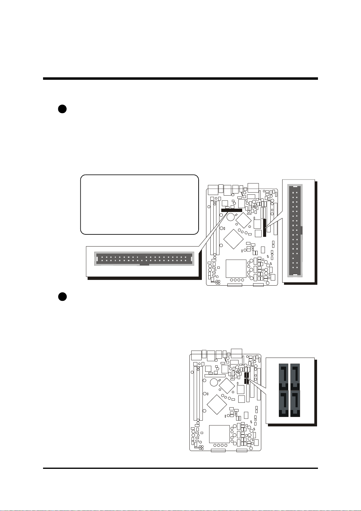
C1
Enhanced IDE, Floppy Connectors
The mainboard features one 40-pin dual-channel IDE device connectors (IDE1)
providing support for up to two IDE devices, such as CD-ROM and Hard Disk
Drives (H.D.D.). This mainboard also includes one 34-pin floppy disk controller (FDC) to accommodate the Floppy Disk Drive (FDD). Moreover, this
mainboard comes with one 80-pin ATA 100/66/33 ribbon cable to connect
to IDE H.D.D. and one 34-pin ribbon cable for F.D.D. connection.
Important: Ribbon cables are directional, therefore, make sure to
always connect with the red cable
stripe on the same side as pin #1 of
the IDE1 or FDC connector on the
mainboard.
1
C2
Serial ATA Connectors
The Serial ATA is an enolutionary replacement for the Parallel ATA physical
storge interface. Serial ATA is scalable and will allow future enhancements to
the computing platform. The Serial ATA interface supports data transfer rates
up to 150MB/s.
IDE1
- 32 -
Page 38
F Other Connectors
1
ATX1
1
ATX2
ATX3
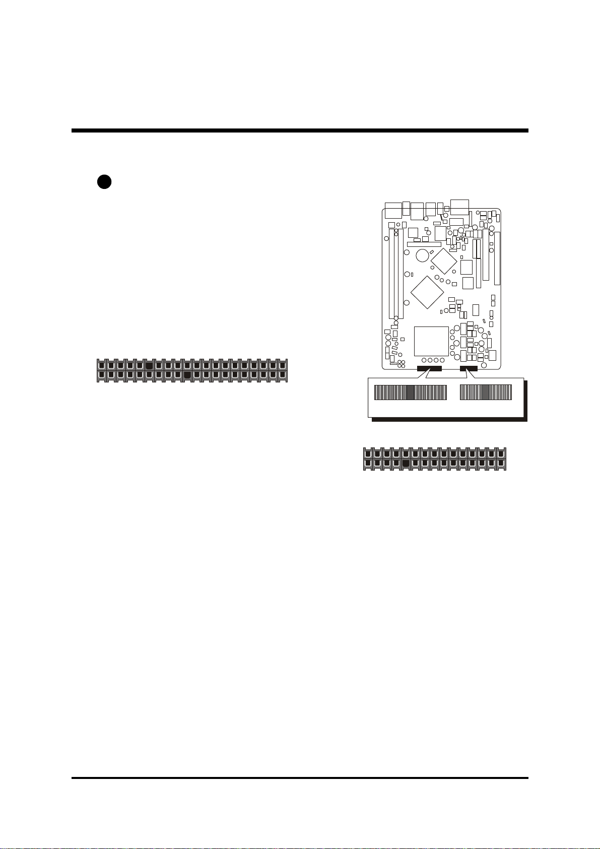
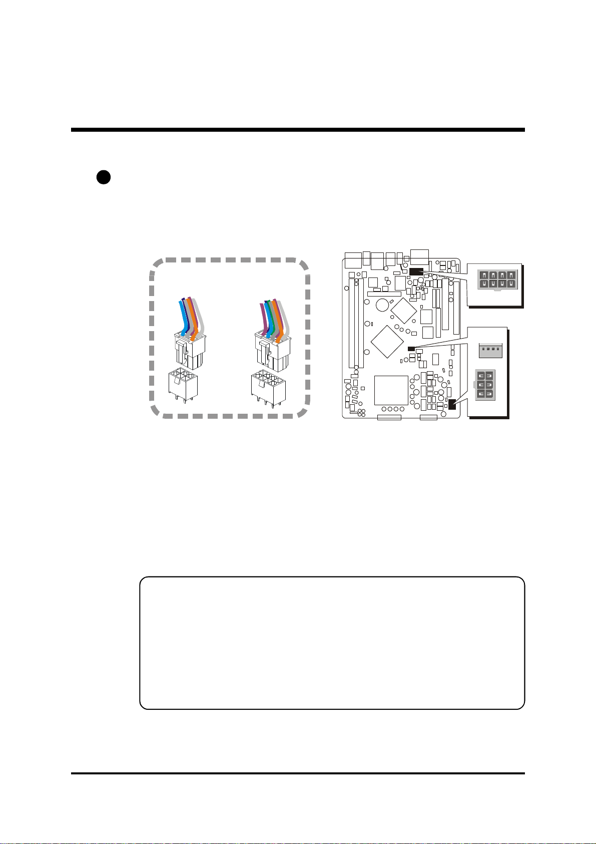
Power Connectors (8-pin ATX2, 6-pin ATX1, 4-pin ATX3)
D1
These connectors connect to an adapted 12V power supply. The plugs from
the power supply are designed to fit these connectors in only one orientation.
Please make sure you plug in the right direction.
ATX1
ATX2
Pin Assignments (ATX1): Pin Assignments (ATX2):
1=GND 4=12VSB 1=GND 5=12VSB
2=GND 5=12VSB 2=GND 6=12VSB
3=GND 6=12VSB 3=GND 7=12VSB
4=NC 8=PS_ON#
1
Note1: The power connector is directional and will not go in unless
the guides match perfectly making sure that pin#1 is properly positioned.
Note2: Make sure the latch of the power connector clicks into place
to ensure a solid attachment.
Note3: Make sure your power supply have enough power for higher
speed processor installed.
- 33 -
Page 39

D2
1
PWM_CTRL
SPEED_SENSE
CN3
123
4
CN4
432
1
FAN3
FAN1
FAN4
1
CD-IN
CN4
CD-IN
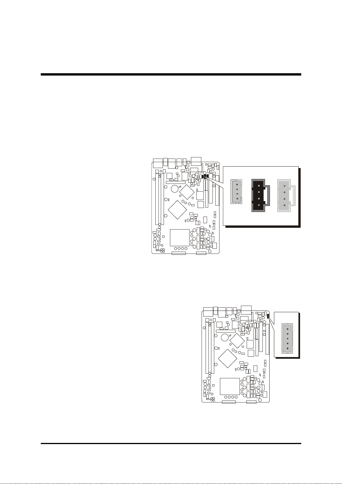
Fan Connectors - FAN1/2/3/4
The mainboard provides four onboard 12V cooling fan power connectors to
support CPU_In (FAN1), CPU_Out (FAN2), System (FAN3), Reserved (FAN4)
cooling fans.
+12V
GND
FAN2
1
Note : Both cable wiring and type of plug may vary , which depends on the
fan maker. Keep in mind that the red wire should always be connected
to the +12V header and the black wire to the ground (GND) header.
D3
CD-IN/Mini CD-IN Connectors (CN3)(Black) / (CN4)(White)
Port CN3 & CN4 are used to attach an audio connector cable from the
CD-ROM drive.
Pin Assignments (CN3):
1=CD-IN Left
2=CD-Ground
1
3=CD-Ground
1
1
1
CN3
4=CD-IN Right
Mini
Pin Assignments (CN4):
1=CD-Ground
2=CD-IN Right
3=CD-Ground
4=CD-IN Left
- 34 -
Page 40

D4
12345
USB2
CN2
123
4
1
AUX-IN
1
USB2
AUX-IN Connector (CN2) (White)
Port CN2 can be used to connect a stereo audio input from CD-ROM,
TV-tuner or MPEG card.
Pin Assignments (CN2):
1=AUX-IN Left
2=Ground
3=Ground
4=AUX-IN Right
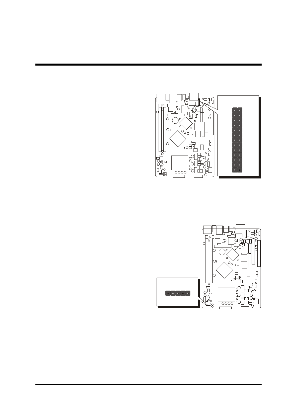
D5
Extended USB Connector (USB2)
The headers are used to connect the cable attached to USB connectors which
are mounted on front-panel or back-panel. But the USB cable is optional at the
time of purchase.
CN2
Pin Assignments:
1=GND
2=GND
3=USB+
4=USB-
5=5VSB
- 35 -
Page 41

D6
54321
14151617181920212223242526
101112
13
1
JP5
EXT. Print Port
Parallel Port Header-EXT. Print Port (JP5)
One DB25 male parallel port header is located at the rear panel of the maiboard.
The header is used to connect the cable attached to parallel connector. But the
parallel cable is optional at the time of purchase.
Pin Assignments (JP5):
1=PSTB
2=PPPD0
3=PPPD1
4=PPPD2
5=PPPD3
6=PPPD4
7=PPPD5
8=PPPD6
1
2
3
4
5
6
7
8
9
9=PPPD7
10=P_-ACK
11=P_BUSY
12=P_PE
13=P_SLCT 14=PAUTOFD 15=P_-ERR 16=PINIT 17=PSLCTIN
18=GND 19=GND 20=GND 21=GND 22=GND
23=GND 24=GND 25=GND 26=KEY
D7
EXT. GPI Header (JP1)
Port JP1 can be used to connect special device.
Pin Assignments:
1=5VSB
2=KEY
3=GND
4=GPI8
5=GPI11
EXT. GPI Header
1
JP1
- 36 -
Page 42

3.3 System Memory Configuration
The FB81 mainboard has two 184-pin DIMM slots that allow you to install
from 128MB up to 2GB of system memory. Each 184-pin DIMM (Dual In-line
Memory Module) Slot can accommodate 128MB, 256MB, 512MB, 1GB and
2GB of PC2700/PC3200 compliant 2.6V single (1 Bank) or double (2 Bank)
side 64-bit wide data path DDR SDRAM modules.
Install Memory:
Install memory in any or all of the banks. The combination shown as follows.
TOTAL 2 DIMM in Single or Dual Channel Mode
up to 4GB and 2GB per DIMM
Density 128 Mbit 256 Mbit 512 Mbit 1024 Mbit
Device Width X8 X16 X8 X16 X8 X16 X8 X16
Single Side 128MB 128MB 256MB 256MB 512MB 512MB 1024MB 1024MB
Double Side 256MB 256MB 512MB 512MB 1024MB N/A 2048MB N/A
Note: 1. Maximum installed memory is 4GB.
2. Double -side X16 DDR-SDRAM chips are not supported.
3. Registered DIMM are not supported.
4. Only unbuffered without ECC DIMM are supported.
Note : You do not need to set any jumper to configure memory since the
BIOS utility can detect the system memory automatically.
You can check the total system memory value in the BIOS "Standard
CMOS Setup" menu.
Upgrade Memory:
You can easily upgrade the system memory by inserting additional DDR SDRAM
modules in available DIMM slots. The total system memory is calculated by
simply adding up the memory in all DIMM slots. After upgrade, the new system
memory value will automatically be computed and displayed in the field "Standard CMOS Setup" of BIOS setup program.
- 37 -
Page 43

4 SOFTWARE UTILITY
4.1 Mainboard CD Overview
Note : The CD contents attached in FB81 mainboard are subject to change
without notice.
To start your mainboard CD disc, just insert it into your CD-ROM drive and
the CD AutoRun screen should appear. If the AutoRun screen does not appear,
double click or run D:\Autorun.exe (assuming that your CD-ROM drive is
drive D:)
Navigation Bar Description:
F Install Mainboard Software - Installing Intel Chipset, Intel VGA,
Intel IAA, Broadcom Giga LAN, Broadcom BACS, Intel USB 2.0,
Intel High Definition Bus, Intel High Definition Audio, and DirectX9 Utility
drivers.
F Install Utility - Installing Acrobat Reader, WinFlash Utility.
F Manual - FB81 Series mainboard user's manual in PDF format.
F Link to Shuttle Homepage - Link to shuttle website homepage.
F Browse this CD - Allows you to see contents of this CD.
F Quit - Close this CD.
- 38 -
Page 44

Note : If you want to install driver automatically, please make sure you
have install WindowsXP(SP1) and Windows2000(SP4).
4.2 Install Mainboard Software
Insert the attached CD into your CD-ROM drive and the CD AutoRun screen
should appear. If the AutoRun screen does not appear, double click on Autorun
icon in My Computer to bring up Shuttle Mainboard Software Setup
screen.
Select using your pointing device (e.g. mouse) on the "Install Mainboard
Software" bar to run into sub-menu.
The Mainboard Software include:
[4.2.A] Install Intel Chipset Driver
[4.2.B] Install Intel VGA Driver
[4.2.C] Install Intel IAA Driver
[4.2.D] Install Broadcom Giga LAN Driver
[4.2.E] Install Broadcom BACS
[4.2.F] Install Intel USB 2.0 Driver
[4.2.G] Install Intel High Definition Bus
[4.2.H] Install Intel High Definition Audio Driver
[4.2.I] Install DirectX9 Utility
- 39 -
Page 45

4.2.A Install Intel Chipset Driver
Click on the "Install Mainboard Software"; then click on the "Install Intel
Chipset Driver" bar to install the chipset driver. Once you made your selection, a Setup window will run the installation automatically. Reboot the system
after the installation.
Once you made your selection, a Setup window
run the installation
automatically.
When the copying files
is done, make sure you
reboot the system to
take the installation
effect.
4.2.B Install Intel VGA Driver
Select using your pointing device (e.g. mouse) on the "Install Intel VGA
Driver" bar to install Intel VGA Driver.
Once you made your selection, a Setup window
run the installation
automatically.
When the copying files
is done, make sure you
reboot the system to
take the installation
effect.
- 40 -
Page 46

4.2.C Install Intel IAA Driver
Select using your pointing device (e.g. mouse) on the "Install Intel IAA Driver"
bar to install IAA Driver.
Once you made your selection, a Setup window run the installation automatically. When the copying files is done, make sure you reboot the system to take
the installation effect.
4.2.D Install Broadcom Giga LAN Driver
Click on the "Install Mainboard Software"; then click on the "Install
Broadcom Giga LAN Driver" bar to install the LAN driver. Once you made
your selection, a Setup window will run the installation automatically. Reboot
the system after the installation.
- 41 -
Page 47

4.2.E Install Broadcom BACS
Click on the "Install Mainboard Software"; then click on the "Install
Broadcom BACS" bar to install the Broadcom BACS driver. Once you made
your selection, a Setup window will run the installation automatically. Reboot
the system after the installation.
4.2.F Install Intel USB 2.0 Driver
Click on the "Install Mainboard Software"; then click on the "Install Intel
USB 2.0 Driver" bar to install the USB 2.0 driver. Once you made your selection, a Setup window will run the installation automatically. Reboot the system
after the installation.
Important:
Under Win 98/Me,
please check the
"Read me" file and
follow steps for
manual installation.
Once you made your selection, a Setup window run the installation automatically. When the copying files is done, make sure you reboot the system to take
the installation effect.
- 42 -
Page 48

4.2.G Install Intel High Definition Bus
Click on the "Install Mainboard Software"; then click on the "Install Intel
High Definition Bus" bar to install the High Definition Bus driver. Once you
made your selection, a Setup window will run the installation automatically.
Reboot the system after the installation.
4.2.H Install Intel High Definition Audio Driver
Click on the "Install Mainboard Software"; then click on the "Install Intel
High Definition Audio Driver" bar to install the High Definition Audio driver.
Once you made your selection, a Setup window run the installation automatically. When the copying files is done, make sure you reboot the system to take
the installation effect.
- 43 -
Page 49

4.2.I Install DirectX9 Utility
Select using your pointing device (e.g. mouse) on the "Install DirectX9
Utility" bar to install DirectX9.
Once you made your selection, a Setup window run the installation automatically. When the copying files is done, make sure you reboot the system to take
the installation effect.
- 44 -
Page 50

4.3 View the User's Manual
Insert the attached CD into your CD-ROM drive and the CD AutoRun screen
should appear. If the AutoRun screen does not appear, double click on AutoRun
icon in My Computer to bring up Shuttle Mainboard Software Setup
screen. Then Online Information windows will appear on your screen. Click
on the "Install Acrobat Reader" bar if you need to install acrobat reader.
Select using your pointing device (e.g. mouse) on the "Manual" bar.
Then click on "FB81 Manual" bar to view user's manual.
Then click on "ICH6R Manual" bar to view RAID manual.
- 45 -
Page 51

5 BIOS SETUP
FB81 BIOS ROM has a built-in Setup program that allows users to modify the
basic system configuration. This information is stored in battery-backed RAM
so that it retains the Setup information even if the system power is turned off.
The system BIOS is managing and executing a variety of hardware related functions in the system, including:
System date and time
Hardware execution sequence
Power management functions
Allocation of system resources
5.1 Enter the BIOS
To enter the BIOS (Basic Input / Output System) utility, follow these steps:
Step 1. Power on the computer, and the system will perform its
POST (Power-On Self Test) routine checks.
Step 2. Press <Del> key immediately, or at the following message:
Press DEL to enter SETUP, or simultaneously press <Ctrl>,
<Alt>, <Esc> keys
Note1. If you miss trains of words mentioned in step2 (the message dis-
appears before you can respond) and you still wish to enter BIOS
Setup, restart the system and try again by turning the computer
OFF and ON again or by pressing the <RESET> switch located
at the computer’s front-panel. You may also reboot by simultaneously pressing the <Ctrl>,<Alt>, <Del> keys simultaneously.
Note2. If you do not press the keys in time and system does not boot, the
screen will prompt an error message, and you will be given the
following options:
"Press F1 to Continue, DEL to Enter Setup”
Step 3. As you enter the BIOS program, the CMOS Setup Utility will
prompt you the Main Menu, as shown in the next section.
- 46 -
Page 52

5.2 The Main Menu
Once you enter the AwardBIOS(tm) CMOS Setup Utility, the Main
Menu will appear on the screen. The Main Menu allows you to select
from several setup functions and two exit choices. Use the arrow keys
to select among the items and press <Enter> to accept and enter the
sub-menu.
Note that a brief description of each highlighted selection appears at the
bottom of the screen.
Setup Items
The main menu includes the following main setup categories. Recall
that some systems may not include all entries.
Standard CMOS Features
Use this menu for basic system configuration.
Advanced BIOS Features
Use this menu to set the Advanced Features available on your system.
Advanced Chipset Features
Use this menu to change the values in the chipset registers and optimize your system's performance.
Integrated Peripherals
Use this menu to specify your settings for integrated peripherals.
Power Management Setup
Use this menu to specify your settings for power management.
PnP / PCI Configurations
This entry appears if your system supports PnP / PCI.
- 47 -
Page 53

PC Health Status
This entry shows the current system temperature, Voltage, and FAN
speed.
Frequency/Voltage Control
Use this menu to specify your settings for frequency/voltage control.
Load Fail-Safe Defaults
Use this menu to load the BIOS default values for the minimal/stable
performance of your system to operate.
Load Optimized Defaults
Use this menu to load the BIOS default values that are factory-set for
optimal performance system operation. While Award has designed the
custom BIOS to maximize performance, the factory has the right to
change these defaults to meet users' needs.
Set Supervisor / User Password
Use this menu to change, set, or disable password. It allows you to limit
access to the system and Setup, or only to Setup.
Save & Exit Setup
Save CMOS value changes in CMOS and exit from setup.
Exit Without Saving
Abandon all CMOS value changes and exit from setup.
- 48 -
Page 54
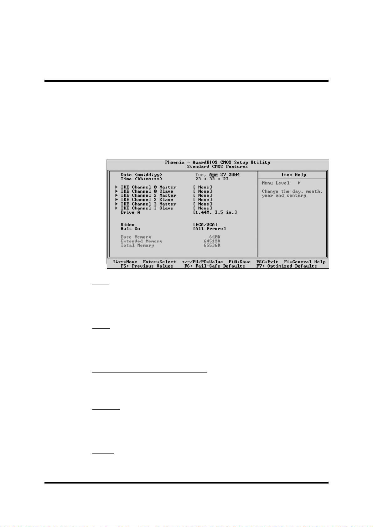
@ Standard CMOS Features
The items in Standard CMOS Setup Menu are divided into several categories. Each category includes no, one or more than one setup items.
Use the arrow keys to highlight the item and then use the <PgUp> or
<PgDn> keys to select the value you want in each item.
Date
<Month> <DD> <YYYY>
Set the system date. Note that the 'Day' automatically changes when you
set the date.
Time
<HH : MM : SS>
The time is converted based on the 24-hour military-time clock.
For example, 5 p.m. is 17:00:00.
IDE Channel 0/2/3 Master/Slave
Options are in its sub-menu.
Press <Enter> to enter the sub-menu of detailed options.
Drive A
Select the type of floppy disk drive installed in your system.
Ø The choice: None, 360K, 5.25 in, 1.2M, 5.25 in, 720K, 3.5 in,
1.44M, 3.5 in, or 2.88M, 3.5 in.
Video
Select the default video device.
Ø The choice: EGA/VGA, CGA 40, CGA 80, or MONO.
- 49 -
Page 55

Halt On
Select the situation in which you want the BIOS to stop the POST process
and notify you.
Ø The choice: All Errors, No Errors, or All, But Keyboard.
Base Memory
Displays the amount of conventional memory detected during boot up.
Ø The choice: N/A.
Extended Memory
Displays the amount of extended memory detected during boot up.
Ø The choice: N/A.
Total Memory
Displays the total memory available in the system.
Ø The choice: N/A.
******************************************************
IDE Adapters
The IDE adapters control the hard disk drive. Use a separate sub-menu to
configure each hard disk drive.
IDE HDD Auto-Detection
Press <Enter> to auto-detect HDD on this channel. If detection is successful, it fills the remaining fields on this menu.
Ø Press Enter
IDE Channel 0 Master
Selecting 'manual' lets you set the remaining fields on this screen and
select the type of fixed disk. "User Type" will let you select the number of
cylinders, heads, etc., Note: PRECOMP=65535 means NONE !
Ø The choice: None, Auto, or Manual.
Access Mode
Choose the access mode for this hard disk.
Ø The choice: CHS, LBA, Large, or Auto.
Capacity
Disk drive capacity (Approximated). Note that this size is usually slightly
greater than the size of a formatted disk given by a disk checking program.
Ø Auto-Display your disk drive size.
- 50 -
Page 56

The following options are selectable only if the 'IDE Primary Master'
item is set to 'Manual', and Access mode set to CHS.
Cylinder
Set the number of cylinders for this hard disk.
Ø Min = 0, Max = 65535
Head
Set the number of read/write heads.
Ø Min = 0, Max = 255
Precomp
Warning: Setting a value of 65535 means no hard disk.
Ø Min = 0, Max = 65535
Landing zone
Set the Landing zone size.
Ø Min = 0, Max = 65535
Sector
Number of sector per track.
Ø Min = 0, Max = 255
******************************************************
- 51 -
Page 57
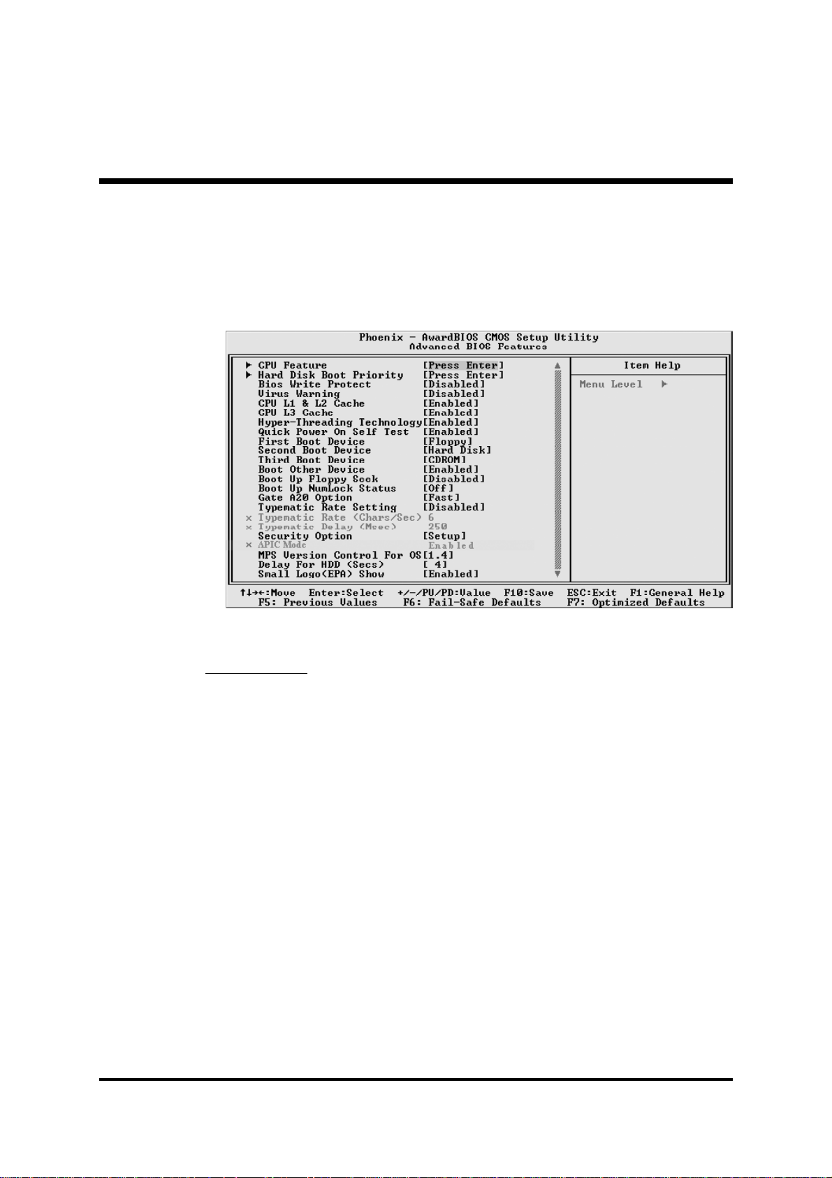
@ Advanced BIOS Features
This section allows you to configure your system for basic operation.
You have the opportunity to select the system's default speed, boot-up
sequence, keyboard operation, shadowing, and security.
CPU Feature
Options are in its sub-menu.
Press <Enter> to enter the sub-menu of detailed options.
Delay Prior to Thermal
This item is select Delay Prior to Thermal.
Ø The Choice: 4Min, 8Min, 16Min or 32 Min.
Thermal Management
This item is select Thermal Management .
Thermal Monitor 1 (On die throtting)
Thermal Monitor 2 (Ratio & VID transition )
Ø The Choice: Thermal Monitor 1 or Thermal Monitor 2.
TM2 Bus Ratio
Represents the frequency (bus ratio of the throttled performance statethat
will be initiated when the on-diesensor gose from not hot to hot.
Ø The Choice: Min=0, Max=255.
- 52 -
Page 58

TM2 Bus VID
Represents the voltageof the throttled performance statethat will be initiated when the on diesensor gose from not hot to hot.
Ø The Choice: 0.8375V ~1.6000V.
Limit CPUID MaxVal
Set Limit CPUID MaxVal to 3,Should Be "Disabled" for WinXp.
Ø The Choice: Disabled or Enabled.
NX BIOS Control
This item allows you to enable/disable the NX BIOS Control.
Ø The choice: Enabled or Disabled.
Hard Disk Boot Priority
This item allows you to select Hard Disk Book Device Priority.
Bios Write Protect
This item allows you to enable or disable the Bios Write Protect.
If you want to flash BIOS, you must set it [Disabled].
Ø The choice: Enabled or Disabled.
Virus Warning
Allows you to choose the VIRUS Warning feature for IDE Hard Disk boot
sector protection. If this function is enables and someone attempts to write
data into this area, BIOS will show a warning message on screen, and an
alarm beep.
Enabled Activates automatically when the system boots up,
causing a warning message to appear when anything
attempts to access the boot sector or hard disk
partition table.
Disabled No warning message will appear when anything
attempts to access the boot sector or hard disk
partition table.
Ø The choice: Enabled or Disabled.
CPU L1&L2&L3 Cache
All processors that can be installed in this mainboard use internal level1(L1)
, external 2(L2) cache memory and (L3) to imporve performance.
Leave this item at the default value for better performance.
Ø The choice: Enabled or Disabled.
Note: CPU support, L3 item appear.
- 53 -
Page 59

Hyper-Threading Technology
The latest Intel application defines a high-speed calculating ability to
optimize your system by two CUPs supported(one virtual, one physical)
in a multi-task environment. "Enabled" for Windows XP and Linux
2.4.x(OS optimized for Hyper Threading Technology and "Disable" for
other OS(OS not optimized for Hyper Threading Technology)
Ø The choice: Enabled or Disabled.
Quick Power On Self Test
This item speeds up Power-On Self Test (POST) after you power on the
computer. If it is set to enabled, BIOS will shorten or skip some check
items during POST.
Ø The choice: Enabled or Disabled.
First/Second/Third Boot Device
The BIOS attempts to load the operating system from the devices in the
sequence selected in these items.
Ø The Choice: Floppy, LS120, Hard Disk, CDROM, ZIP100, USB-FDD,
USB-ZIP,USB-CDROM, LAN or Disabled.
Boot Other Device
If BIOS can't load O.S. from First/Second/Third boot device you select
above, BIOS will search other devices and attempt to load O.S..
Ø The choice: Enabled or Disabled.
Boot Up Floppy Seek
Seeks disk drives during boot-Up. Disabling speed boots up.
Ø The choice: Enabled or Disabled.
Boot Up NumLock Status
Selects power-on state for NumLock.
Ø The choice: Off or On.
Gate A20 Option
This entry allows you to select how the Gate A20 is handled. The gate
A20 is a device used for above 1MByte of address memory. Initially, the
gate A20 was handled via a pin on the keyboard. Today, while a keyboard still provides this support, it is more common and much faster in
setting to fast for the system chipset to provide support for gate A20.
Ø The choice: Normal or Fast.
- 54 -
Page 60

Typematic Rate Setting
Keystrokes repeat at a rate determined by the keyboard controller. When
this controller enabled, the typematic rate and typematic delay can be
selected.
Ø The choice: Enabled or Disabled.
Typematic Rate (Chars/Sec)
This item sets how many times the keystroke will be repeat in a second
when you hold the key down.
Ø The choice: 6, 8, 10, 12, 15, 20, 24 or 30.
Typematic Delay (Msec)
Sets the delay time after the key is held down before it begins to repeat the
keystroke.
Ø The choice: 250, 500, 750 or 1000.
Security Option
Select whether the password is required every time the system boots or
only when you enter setup.
System The system will not boot and access to Setup will be denied
if the correct password is not entered promptly.
Setup The system will boot, but access to Setup will be denied if the
correct password is not entered promptly.
Ø The choice: System or Setup.
Note : To disabled security, select PASSWORD SETTING at Main
Menu, and then you will be asked to enter password. Don't
type anything and just press <Enter>; it will disable security.
Once the security is disabled, the system will boot, and you
can enter Setup freely.
APIC Mode
Via the routing, I/O APIC support a total of 24 interrupts. Always "Enabled".
Ø The choice: Enabled or Disabled.
MPS Version Control For OS
Selects the operating system multiprocessor support version.
Ø The choice: 1.1 or 1.4.
- 55 -
Page 61

Delay For HDD (Secs)
The item allows you to set delay for HDD.
Min=0, Max=15. The default value is 4 secs..
Ø The choice: Key in a DEC number. (Between Min and Max)
Small Logo(EPA) Show
This item allows you to enable/disable the EPA Logo.
Ø The choice: Enabled or Disabled.
- 56 -
Page 62

@ Advanced Chipset Features
This section allows you to configure the system based on the specific
features of the installed chipset. This chipset manages bus speeds and access
to system memory resources, such as DRAM and the external cache. It also
coordinates communications between the conventional ISA bus and the PCI
bus. It states that these items should never need to be altered.
The default settings have been chosen because they provide the best
operating conditions for your system. If you discovered that data was being
lost while using your system, you might consider making any changes.
System BIOS Cacheable
Selecting Enabled allows caching of the system BIOS ROM at
F0000h~FFFFFh, resulting in better system performance. However, if any
program is written to this memory area, a system error may result.
Ø The Choice: Enabled or Disabled.
Video BIOS Cacheable
Selecting Enabled allows caching of the video BIOS, resulting in better
system performance. However, if any program is written to this memory
area, a system error may result.
Ø The Choice: Enabled or Disabled.
Memory Hole At 15M-16M
You can reserve this area of system memory for ISA adapter ROM. When
this area is reserved, it can't be cached. The user information of peripherals that need to use this area of system memory usually discusses their
memory requirements.
Ø The Choice: Enabled or Disabled.
- 57 -
Page 63

********** VGA Setting **********
PEG/Onchip VGA Control
If you select "Onchip VGA", the signal will only output from Onchip
VGA Port. If you want to use external PEG Card, please change display
mode from Onchip VGA to PEG Port in this item.
Ø The choice: Disabled, Auto, Onchip VGA or PEG Port .
PEG Force X1
This item allows you to enable or disable On-Chip PEG.
Ø The Choice: Enabled or Disabled.
On-Chip Video Memory size
You can "Press Enter" to onboard Video memory size.
On-Chip Frame Buffer Size
This item allows you to set the onboard VGA share memory size.
Ø The Choice: 1MB, 4MB, 8MB, 16MB or 32MB.
FIXED Memory Size
This item allows you to set the FIXED Memory Size.
Ø The Choice: 0 MB, 56 MB, 63 MB, 120 MB or 127 MB.
DVMT Memory Size
This item allows you to set the DVMT Memory Size.
Ø The Choice: 0 MB, 56 MB, 63 MB, 120MB, 127 MB or
MAX.DVMT.
- 58 -
Page 64

@ Integrated Peripherals
On-Chip IDE Device
Option are in its sub-menu.
Press<Enter>to enter the sub-menu of detailed options.
IDE HDD Block Mode
If your IDE hard disk drive supports block mode (most new drives do),
select Enabled to automatic detect the optimal number of block read
and writes per sector that the drive can support and improves the
speed of access to IDE devices.
Ø The choice: Enabled, or Disabled.
IDE DMA transfer access
Improve IDE HD/CDROM transfer performance.
Ø The choice: Enabled or Disabled.
On-Chip Primary PCI IDE
Use these items to enable or disable the PCI IDE channels that are
integrated on the mainboard.
Ø The choice: Enabled or Disabled.
IDE Primary Master/Slave PIO
Each IDE channel supports a master device and a slave device. These
four items let you assign which kind of PIO ( Programmed Input / Output ) is used by IDE devices. Choose Auto to let the system auto detect
which PIO mode is best or select a PIO mode from 0-4.
Ø The choice: Auto, Mode 0, Mode 1, Mode 2, Mode 3, or Mode 4.
- 59 -
Page 65
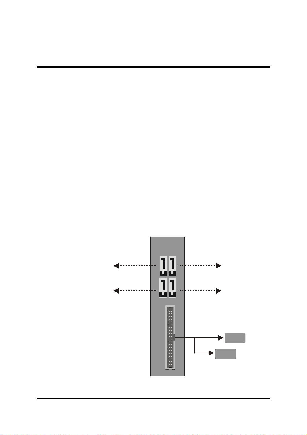
IDE Primary Master/Slave UDMA
Master
Slave
Disable
Serial ATA 4
Serial ATA 2
Each IDE channel supports a master device and a slave device. This
mainboard supports UltraDMA technology, which provides faster access
to IDE devices.
If you install a device that supports UltraDMA, change the appropriate
item on this list to Auto. You may have to install the UltraDMA driver
supplied with this mainboard in order to use an UltraDMA device.
Ø The Choice: Auto or Disabled.
********** On -Chip Serial ATA Setting **********
SATA Mode
This item allows you to set the SATA Mode.
Ø The choice: IDE, RAID or AHCI.
On-Chip Serial ATA
Ø The Choice: Disabled, Enhanced Mode or SATA Only.
Disabled : Disabled SATA Controller.
Disable
Serial ATA 3
Serial ATA 1
Serial
ATA
Parallel ATA
IDE1
(Channel 0)
- 60 -
Page 66

Enhanced Mode: Enable both SATA and PATA. Max. of 6 ATA drives
lAT
A
Master
Slave
Serial ATA 4
Serial ATA 2
Master
(Channel 3)
(Channel 3)
lAT
A
Serial ATA 4
Serial ATA 2
Master
(Channel 1)
(Channel 1)
Disable
are supported.
New OS that support switch to Enhanced mode (WinXP,Windows.NET
Server) can set SATA and PATA to Enhanced Mode.
Serial
ATA
Serial ATA 3
(Channel 2)
(Channel 2)
Slave
Serial ATA 1
Master
IDE1
Slave
(Channel 0)
Paralle
SATA-Only:SATA is operating in legacy mode.
Serial
ATA
Serial ATA 3
(Channel 0)
(Channel 0)
Slave
Serial ATA 1
Master
Paralle
Slave
IDE1
- 61 -
Page 67

SATA Hot-Plug
This item can be enabled. When SATA mode item be set in "RAID" or
"AHCI" mode.
Ø The Choice: Disabled or Enabled.
Note: You must to install Intel Application Accelerator (IAA) in O.S. to
make sure this function work properly.
Onboard Device
Option are in its sub-menu.
Press<Enter>to enter the sub-menu of detailed options.
USB Controller
Select Enabled if your system contains a Universal Serial Bus (USB) port
on this mainboard.
Ø The choice: Enabled or Disabled.
USB 2.0 Controller
This entry is for disable/enable EHCI controller only.This BIOS itself may/
may not have high speed USB support. If the BIOS has high speed USB
support built in, the support will be automatically turn on when high speed
device were attached.
Ø The choice: Enabled or Disabled.
High Definition Audio
This item is used to defined High Definition Audio.
Ø The Choice: Auto or Disabled.
Onboard LAN Boot ROM
Decide whether to invoke the boot ROM of the onboard LAN chip.
Ø The choice: Enabled or Disabled.
SuperIO Device
Option are in its sub-menu.
Press<Enter>to enter the sub-menu of detailed options.
Onboard FDC Controller
This item specifices onboard floppy disk drive controller. This setting
- 62 -
Page 68

allows you to connect your floppy disk drives to the onboard floppy
connector.
Ø The choice: Enabled or Disabled.
Onboard Serial Port1
This option is used to assign the I/O address and interrupt request ( IRQ )
for the onboard serial port1 ( COM1 ).
Ø The choice : Disabled, 3F8/IRQ4, 2F8/IRQ3, 3E8/IRQ4, 2E8/IRQ3 or
Auto.
Onboard Parallel Port
This item allows you to determine onboard parallel port controller I/O
address and interrupt request ( IRQ ).
Ø The choice: 378/IRQ7, 278/IRQ5, 3BC/IRQ7 or Disabled.
Parallel Port Mode
Select an operating mode for the onboard parallel (printer) port. Select
Normal, Compatible, or SPP unless you are certain your hardware and
software both support one of the other available modes.
Ø The choice: SPP, EPP, ECP or ECP+EPP.
ECP Mode Use DMA
When the onboard parallel is set to ECP mode, the parallel port can use
DMA3 or DMA1.
Ø The choice: 1 or 3.
- 63 -
Page 69
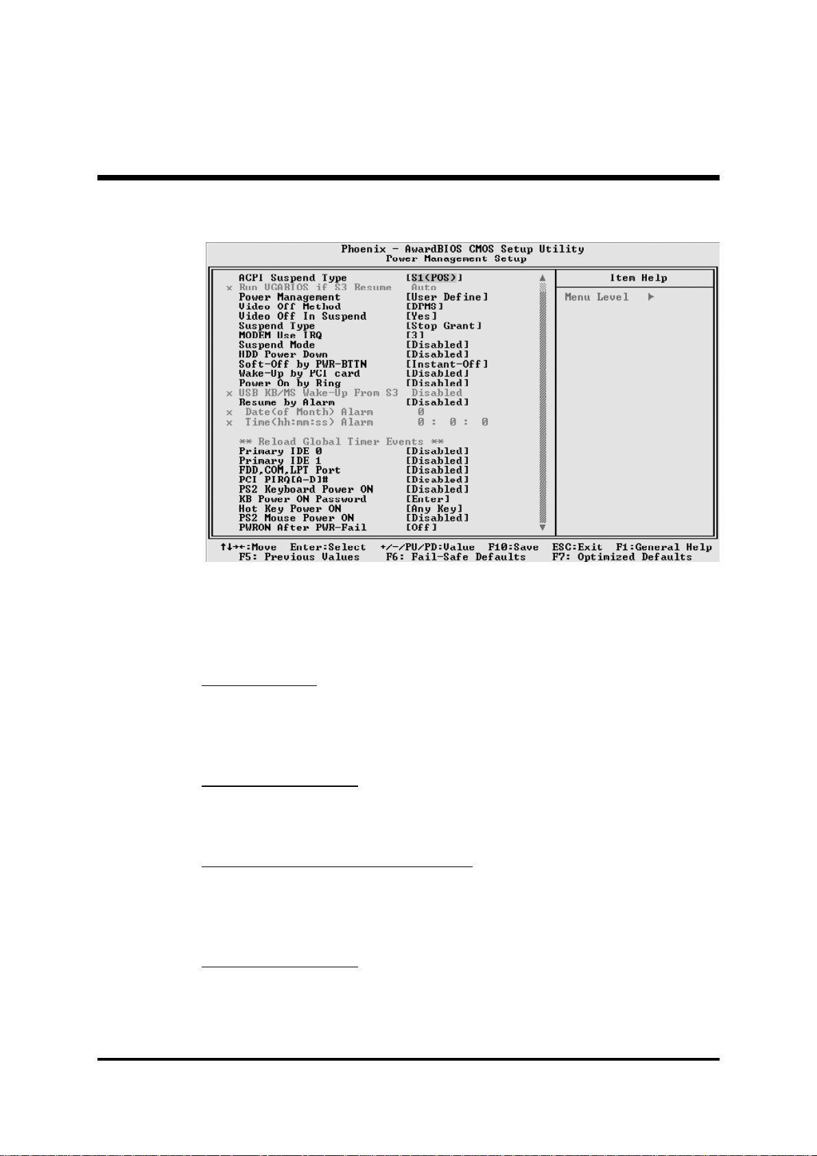
@ Power Management Setup
The Power Management Setup allows you to configure your system to
most effectively saving energy while operating in a manner consistent
with your own style of computer use.
ACPI Function
This item allows you to enable/disable the Advanced Configuration and
Power Management (ACPI).
Ø Always "Enabled".
ACPI Suspend Type
This item allows you to select sleep state when suspend.
Ø The choice: S1(POS), S3(STR) or S1 & S3.
Run VGABIOS if S3 Resume(Auto)
This item allows the system to initialize the VGA BIOS from S3(Suspend to RAM) sleep state.
Ø The choice: Auto, Yes or No.
Power Management
This item allows you to decide the timing to enter suspend mode.
Ø The choice: User Define, Min Saving or Max Saving.
- 64 -
Page 70

Video Off Method
This determines the manner in which the monitor is blanked.
V/H SYNC+Blank This selection will cause the system to turn off
the vertical and horizontal synchronization
ports and write blanks to the video buffer.
Blank Screen This option only writes blanks to the video
buffer.
DPMS Initial display power management signaling.
Ø The choice: V/H SYNC+Blank, Blank Screen or DPMS.
Video Off In Suspend
This item determines the manner in which the monitor is blanked.
Ø The choice: Yes or No.
Suspend Type
This item allows you to select the Suspend Type.
Ø The choice: Stop Grant or PwrOn suspend.
MODEM Use IRQ
This determines the IRQ which the MODEM can use.
Ø The choice: 3, 4, 5, 7, 9, 10, 11 or NA.
Suspend Mode
When this item enabled and after the set up time of system inactivity, all
devices except the CPU will be shut off.
Ø The choice: Disabled, 1Min, 2Min, 4Min, 8Min, 12Min, 20Min,
30Min, 40Min or 1Hour.
HDD Power Down
When this item enabled and after the set up time of system inactivity, the
hard disk drive will be powered down while all other devices remain
active.
Ø The choice: Disabled or 1 Min~15 Min.
Soft-Off by PWR-BTTN
Under ACPI you can create a software power down. In a software power
down, the system can be resumed by Wake UP Alarms. This item lets you
install a software power down that is controlled by the power button on
your system. If the item is set to Instant-Off, then the power button causes
a software power down. If the item is set to Delay4 Sec. then you have to
- 65 -
Page 71

hold the power button down for 4 seconds to cause a software power
down.
Ø The choice: Instant-Off or Delay 4 Sec.
Wake-Up by PCI card
This item Enabled/Disabled PCI Power Management Event to wake up
system.
Ø The choice: Enabled or Disabled.
Power On by Ring
This item determine the system will resume by activating of modem ring.
Ø The choice: Enabled or Disabled.
USB KB/MS Wake-up From S3
If you are using a USB KB/MS, and the ACPI suspend type is set to S3, or
S1&S3 you can enable this item to allow a KB/MS to wake up the system
from power saving mode.
Ø The choice: Enabled or Disabled.
Resume by Alarm
When this item enabled, your can set the date (day of the month) and
time to turn on your system.
Ø The choice: Disabled or Enabled.
Date (of Month) Alarm
This item selects the alarm Date (day of the month).
Ø Key in a DEC number: Min=0, Max=31.
Time (hh : mm : ss) Alarm
This item selects the alarm Time.
[hh] Ø Key in a DEC number: Min=0, Max=23.
[mm/ss] Ø Key in a DEC number: Min=0, Max=59.
*** Reload Global Timer Events ***
Global Timer (power management) events are I/O events whose occurrence can prevent the system from entering a power saving mode or
can awaken the system from such as a mode. In effect, the system
remains alert for anything that occurs to a device that is configured as
Enabled, even when the system is in a power-down mode.
Primary IDE 0/1
When these items are enabled, the system will restart the power-saving
- 66 -
Page 72

time out counters when any activity is detected on any of the drives or
devices on the primary IDE channels.
Ø The choice: Disabled or Enabled.
FDD, COM, LPT Port
When this item is enabled, the system will restart the power-saving
timeout counters when any activity is detected on the floppy disk drive,
serial ports, or the parallel port.
Ø The choice: Disabled or Enabled.
PCI PIRQ [A-D] #
When this item is disabled, any PCI device set as the Master will not
power on the system.
Ø The choice: Disabled or Enabled.
PS2 Keyboard Power ON
This item allows you to set the PS2 Keyboard Power On function
Ø The choice: Disabled, Password or Hot Key.
KB Power ON Password
This item allows you to set the KB Power On Password.
If "PS2 Keyboard Power ON" select "Password".
Ø Press" Enter" to set Password.
Hot Key Power ON
This item allows you to set the Hot Key Power On.
If "PS2 Keyboard Power ON" select "Hot Key".
Ø The choice: Any Key or Ctrl-F1~Ctrl-F12.
PS2 Mouse Power ON
This item allows you to enable or disable the PS2 Mouse Power On.
Ø The choice: Disabled or Enabled.
PWRON After PWR-Fail
This item defines if the system will be rebooted after the power fails.
Ø The choice: Off, On or Former-Sts.
- 67 -
Page 73
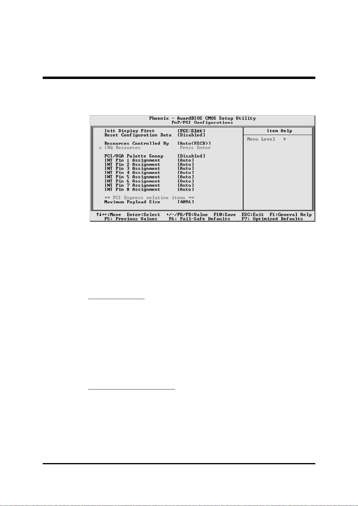
@ PnP/PCI Configurations
This section describes the configuration of PCI bus system. PCI or Personal Computer Interconnection is a system which allows I/O devices to
operate at the speed CPU itself keeps when CPU communicating with its
own special components. This section covers some very technical items,
and it is strongly recommended that only experienced users should make
any changes to the default settings.
Init Display First
When the PAGE56 "PEG/Onchip VGA Control" item is Auto or Onchip
VGA or PEG Port, this item can be selected.
Select the priority of VGA device "PCI Slot" or "Onboard" if there is not
PCI Express VGA Card in system.
Select the priority of VGA device "PCI Slot" or "PCI Ex" if install PCI
Express VGA Card in system.
Ø The choice: PCI Slot, Onboard or PCI Ex.
Reset Configuration Data
Normally, you leave this field Disabled.
Select Enabled to reset Extended System Configuration Data (ESCD) when
you exit from Setup if you have installed a new device or software and the
system reconfiguration has caused such a serious conflict that the operating system can not boot.
Ø The choice: Enabled or Disabled.
- 68 -
Page 74

Resource controlled By
The Award Plug-and-Play BIOS has the capacity to automatically configure all of the boot and Plug-and-Play compatible devices. However, this
capability means absolutely nothing unless you are using a Plug-and-Play
operating system such as Windows 95. If you set this field to "manual" ,
choose specific resources by going into each of the sub-menu that follows this field (a sub-menu is proceeded by a ">").
Ø The choice: Auto(ESCD) or Manual.
IRQ Resources
When resources are controlled manually, assign each system interrupt a
type, depending on the type of device using the interrupt.
IRQ3/4/5/7/10/11/12/14/15 assigned
This item allows you to determine the IRQ assigned to the ISA bus and is
not available to any PCI slot. Legacy ISA for devices is compliant with the
original PC AT bus specification; PCI/ISA PnP for devices is compliant
with the Plug-and-Play standard whether designed for PCI or ISA bus architecture.
Ø The choice: PCI Device or Reserved.
PCI/VGA Palette Snoop
It determines whether the MPEG ISA/VESA VGA Cards can work with
PCI/VGA or not. If you have MPEG ISA/VESA VGA Cards and PCI/
VGA Card worked, Enable this field. Otherwise, please Disable it.
Ø The choice: Enabled or Disabled.
INT Pin1~8 Assignment
Names the interrupt request (IRQ) line assigned to a device connected to
the PCI interface on your system.
Ø The choice: Auto, 3, 4, 5, 7, 9, 10, 11, 12, 14 or 15.
********** PCI Express relative items **********
Maximum Payload Size
Set maximum TLP payload size for the PCI Express devices.
The unit is byte.
Ø The choice: 4096, 2048, 1024, 512, 256 or 128.
- 69 -
Page 75

@ PC Health Status
CPU Fan Speed Control
Set the CPU Fan Speed.
Ø The choice:Smart Fan, 30%, 40%, 50%, 60%, 70%, 80%, 90% or
100%.
Note : Before manually modifying the CPU fan setting, please make
sure fan connectors are plug into the correct fan connector
designations on the mainboard.
SYSTEM Fan Speed Control
Set the System Fan Speed.
Ø The choice:Smart Fan, 30%, 40%, 50%, 60%, 70%, 80%, 90% or
100%.
CPU Temp Tag
The item only for 'smart fan' and you
can choose 'smart fan' on 'CPU Fan
Speed Control'. This feature ranges
from 30 0C to 80 0C, in an increment
of 1 0C. When CPU current temperature over CPU Temp Tag (user set,
default value as 51 0C), CPU fan will
speed up. You can refer to table
below.
Ø The choice: Default 51 0C.
- 70 -
Page 76

CPU Voltage
Chipset Voltage
+3.3V
+5V
+12V
-12V
DDR Voltage
+5VSB
Voltage Battery
CPU Temperature
Fan 1 Speed
Fan 2 Speed
Fan 3 Speed
Fan 4 Speed
Warning : It is Strongly recommended to disable CPU Fan Auto
Guardian feature, if you wish to use other fan cooler,
allowing the fan to run at its default speed.
- 71 -
Page 77

@ Frequency/Voltage Control
Auto Detect PCI Clk
This item allows you to enable/disable auto disable empty PCI Slot
Clock.
Ø The choice: Enabled or Disabled.
Spread Spectrum
This item allows you to enable or disable the spread spectrum modulation.
Ø The choice: Disabled or Enabled.
DRAM Timing Selectable
The value in this field depends on performance parameters of the installed
memory chips(DRAM). Don't change the value from the factory setting
unless you install new memory that has a different performance rating
than the original DRAMs.
Ø The choice: Manual or BySPD.
CAS Latency Time
When synchronous DRAM is installed, the number of clock cycles of
CAS latency depends on the DRAM timing. Don't change this field from
the default value specified by the system designer.
Ø The choice: 2, 2.5 or 3.
- 72 -
Page 78

DRAM RAS# to CAS# Delay
This field lets you insert a timing delay between the CAS and RAS
strobe signals, and you can use it when DRAM is written to, read from,
or refreshed. Faster performance is gained in high speed, more stable
performance, in low speed. This field is applied only when synchronous DRAM is installed in the system.
Ø The choice: Auto, 5, 4, 3 or 2.
DRAM RAS# Precharge
If an insufficient number of cycles is allowed for the RAS to accumulate
its charge before DRAM refresh, the refresh may be-incompleted, and
the DRAM may fail to retain data. Fast gives faster performance; and
Slow gives more stable performance. This field is applied only when
synchronous DRAM is installed in the system.
Ø The choice: Auto, 5, 4, 3 or 2.
Precharge delay (tRAS)
This item allows you to select Precharge delay (tRAS).
Ø The choice: Auto or 4~15.
System Memory Frequency
This item allows you to select System Memory Frequency.
Ø The choice: Auto, 333MHz or 400MHz.
Refresh Mode Select
This item allows you to select Refresh Mode.
Ø The choice: Auto, 7.8us, 15.6us or 64us.
****** Clock ******
Now CPU Frequency
Now DDR Frequency
CPU Clock Ratio
This item allows the user to adjust CPU Clock Ratio.
If CPU is unlocked, item appear.
Ø The Choice: The Clock Ratio depend on CPU.
- 73 -
Page 79

CPU Ratio Fixed 14x
This item allows you enable or disable the CPU ratio fixed 14x.
Ø The choice: Enabled or Disabled.
CPU Clock
This item allows the user to adjust CPU Host Clock.
Min: 100
Max: 355
Ø Key in a DEC number: (Between Min and Max.)
PCI CLK
This item allows you to set PCI clock asynchronous.
Ø The choice: Sync by CPU clock or Fixed 33 MHz.
****** Voltage ******
CPU Voltage
This item allows you to set CPU Voltage.
Ø The choice: 0.825V~1.5875V or Auto.
DDR Voltage
This item allows you to set DDR Voltage.
Ø The choice: Auto, 2.70V, 2.80V or 2.90V.
ChipSet Voltage set
This item allows you to set ChipSet Voltage.
Ø The choice: Auto, 1.60V, 1.70V or 1.80V.
****** LED ******
LED bright setting
This item is used in adjusting POWER-LED & HDD-LED brightness.
Ø The choice: 0%, 25%, 37.5%, 50%, 62.5%, 75%, 87.5% or 100%,
- 74 -
Page 80
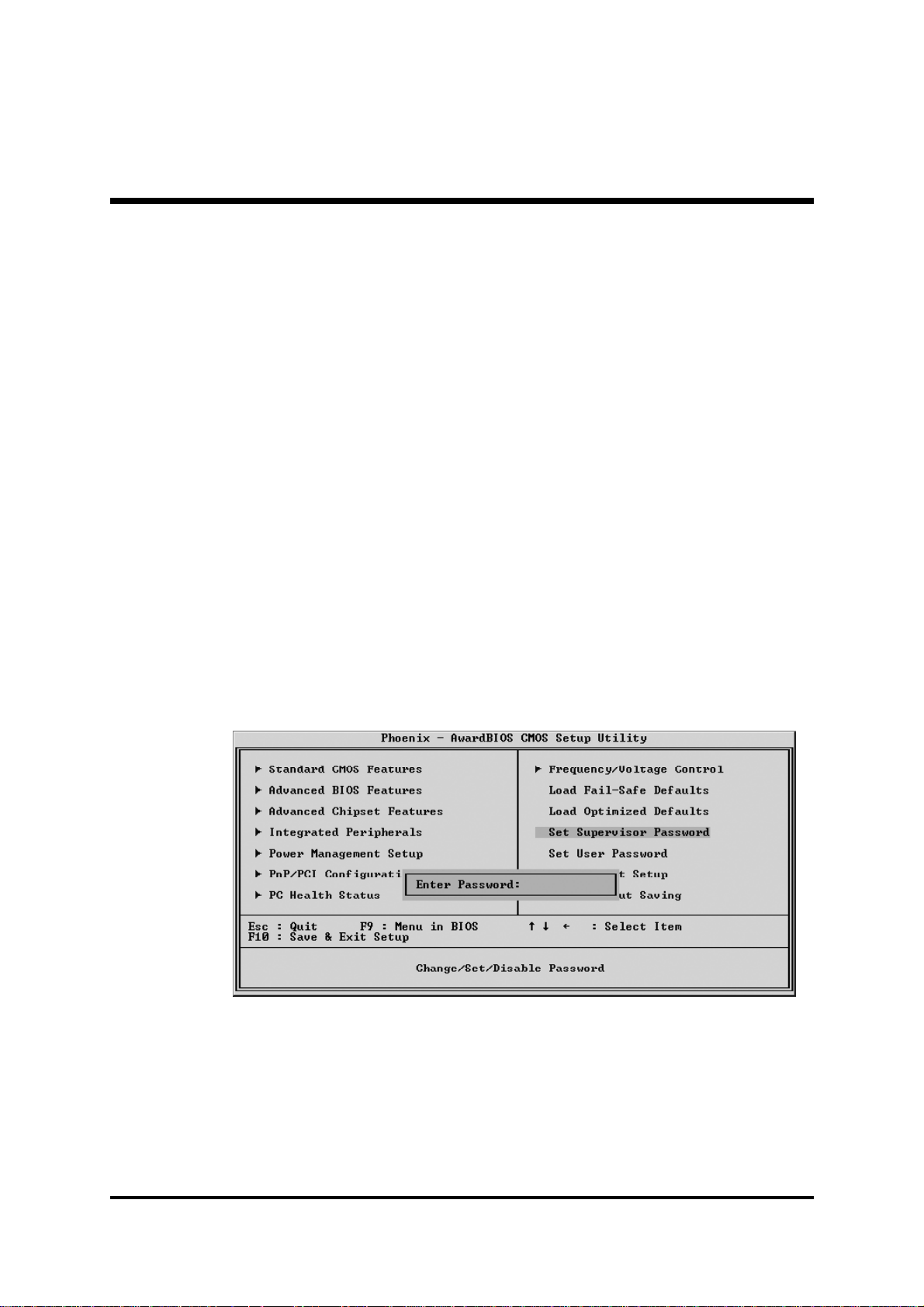
@ Load Fail-Safe Defaults
When you press <Enter> on this item, you will get a confirmation
dialog box with a message similar to:
Load Fail-Safe Defaults (Y/N) ? N
Pressing 'Y' loads the BIOS default values for the most stable,
minimal performance system operations.
@ Load Optimized Defaults
When you press <Enter> on this item, you will get a confirmation
dialog box with a message similar to:
Load Optimized Defaults (Y/N) ? N
Pressing 'Y' loads the default values that are factory-set for
optimal performance system operation.
@ Set Password
This item is to set supervisor password. Please follow below steps.
New Password Setting :
1. While pressing <Enter> key to start setting password function, a
dialog box appears to ask you “Enter password: “.
2. Key in a new password now. However, the password can not be
over eight characters or numbers.
- 75 -
Page 81

3. Then system will request you to confirm new password by asking
you to key in new password again.
4. Once the confirmation is completed, new code takes effect.
No Password Setting :
5. If you want to delete password, just press <Enter> key instead of
new password while password input is requested. And the other
procedures are the same as above password setting.
If You Forget Password :
6. While being asked of password, you just forget it and you must
access the system. The only way is to turn off system and clear
CMOS memory. Please take reference in page 28 for clear
CMOS setting.
@ Save & Exit Setup
Pressing <Enter> on this item asks for confirmation:
Save to CMOS and EXIT (Y/N)? Y
Pressing "Y" stores the selections made in the menus of CMOS - a
special section of memory that stays on after you turn your system off.
The next time you boot your computer, the BIOS configures your
system according to the Setup selections stored in CMOS. After saving
the values the system is restarted again.
@ Exit Without Saving
Pressing <Enter> on this item asks for confirmation:
A3
Quit without saving (Y/N)? Y
This allows you to exit from Setup without storing in CMOS any
change. The previous selections remain in effect. This exits from the
Setup utility and restarts your computer.
- 76 -
 Loading...