

Page 1

XPC Bios User Guide
For the :
DS61
Page 2

Shuttle®
XPC Installation Guide
Copyright
©2012 by Shuttle® Inc. All Rights Reserved.
No part of this publication may be reproduced, transcribed, stored in a retrieval system,
translated into any language, or transmitted in any form or by any means such as electronic,
mechanical, magnetic, optical, chemical, photocopy, manual, or otherwise, without prior
written permission from Shuttle® Inc.
Other brands and product names used herein are for identification purposes only and may
be trademarks of their respective owners.
Disclaimer
Shuttle® Inc. shall not be liable for any incidental or consequential damages resulting from
the performance or use of this product.
Shuttle® Inc. makes no representation or warranty regarding the contents of this manual. Information in this manual had been carefully checked for accuracy;however, no
guarantee is given as to the correctness of the contents. For continuing product improvement, Shuttle® Inc. reserves the right to revise the manual or make changes to the specifications of this product at any time without notice and obligation to any person or entity
regarding such change. The information contained in this manual is provided for general
use by customers.
This device complies to Part 15 of the FCC Rules. Operation is subject to the following
two conditions:
1. This device may not cause harmful interference.
2. This device must withstand any background interference including those that may
cause undesired operation.
Trademarks
Shuttle is a registered trademark of Shuttle Inc.
Intel and Pentium are registered trademarks of Intel Corporation.
PS/2 is a registered trademark of IBM Corporation.
AWARD is a registered trademark of Award Software Inc.
Microsoft and Windows are registered trademarks of Microsoft Corporation.
General Notice
Other brand and product names used herein are for identification purposes only and
may be trademarks of their respective owners.
Page 3
Safety Information
Read the following precautions before setting up a Shuttle XPC.
CAUTION
Incorrectly replacing the battery may damage this computer. Replace only
with the same or equivalent as recommended by Shuttle. Disposal of used
batteries according to the manufacturer's instructions.
Installation Notices
Do not place this device
underneath heavy loads
or in an unstable position.
Do not use or expose this device
around magnetic elds as magnetic
interference may affect the
performance of the device.
Do not expose this device to high
levels of direct sunlight, high-
humidity or wet conditions.
Do not block the air vents
to this device or impede the
airow in any way.
Page 4

安全資訊
請在安裝
Shuttle XPC
前閱讀以下注意安全資訊。
警告
更換電池方式錯誤可能會損壞本電腦以及引發爆炸、火災或其他
危險。
僅能依
請依照製造商的使用說明處理廢電池。
安裝聲明
Shuttle
的建議,以相同或同等的電池更換。
切勿在此設備上放置重物
或將其置於不穩定的位置。
切勿在磁場附近使用此設備,
否則磁場干擾會影響設備的性能。
切勿讓此設備暴露於陽光
直接照射、濕度高、或潮
濕的環境中。
切勿阻塞此設備的通風口
或者以任何方式妨礙空氣流
動。
Page 5

安全信息
请在安装
安装声明
Shuttle XPC
前阅读以下注意安全信息。
注意
更换电池方式错误可能会损坏本电脑。
仅能依
请依照制造商的使用说明处理废电池。
Shuttle
的建议, 以相同或同等的电池更换。
切勿在此设备上放置重物
或将其置于不稳定的位置。
切勿在磁场附近使用此设备,
否则磁场干扰会影响设备的性能。
切勿让此设备暴露于阳光
直接照射、湿度高、或潮
湿的环境中。
切勿阻塞此设备的通风口
或者以任何方式妨碍空气流
动。
Page 6

TABLE OF CONTENTS
Driver and Software Installation........................................................1
Motherboard Driver DVD ...........................................................1
User Manuals.............................................................................2
Appendix...........................................................................................3
Starting BIOS .............................................................................3
BIOS Setup Menu ......................................................................3
Main Setup ..........................................................................5
Advanced ............................................................................6
Power Management Conguration ..............................7
CPU Conguration .......................................................8
SATA Conguration ...................................................10
USB Conguration .....................................................11
Hardware Health Conguration ..................................12
OnBoard Device Conguration ..................................13
Boot...................................................................................15
Security .............................................................................16
Save & Exit .......................................................................18
Page 7
Driver and Software Installation
Motherboard Driver DVD
The DVD contents attached in DS61 Series motherboard are subject to
change without notice.
The Motherboard Driver DVD contains all the motherboard drivers necessary to
optimize the performance of this Shuttle Xvision in a Windows® OS. Install these
drivers after installing Microsoft® Windows®.
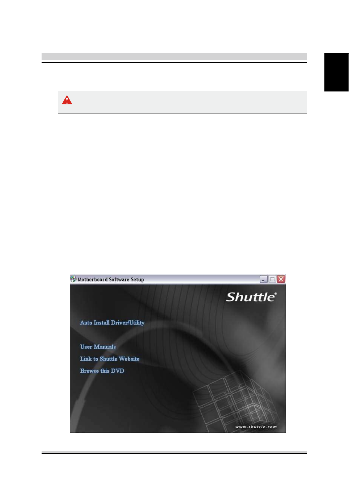
Insert the attached DVD into your DVD-ROM drive. The DVD AutoRun screen
should appear. If the AutoRun screen does not appear, double click on Autorun
icon in My Computer to bring up Shuttle Mainboard Software Setup screen.
Navigation Bar Description :
Auto Install Driver/ Utility.
User Manuals - Motherboard Manual
Link to Shuttle Website - Link to shuttle website homepage.
, Quick Guide.
English
Browse this DVD - Allows you to see contents of this DVD.
1
Page 8
English
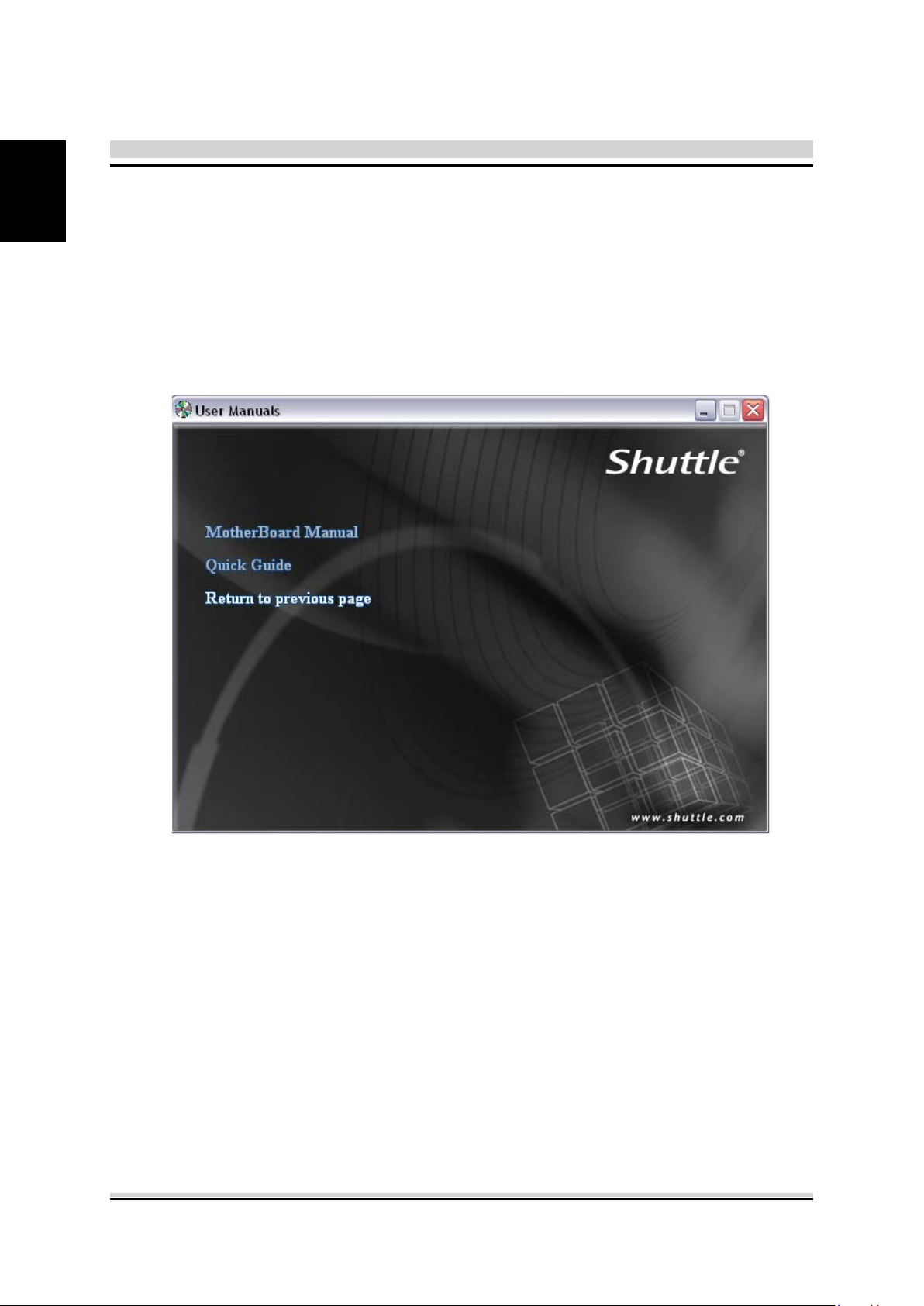
User Manuals
Motherboard Manual
Quick Guide
2
Page 9

Appendix
Starting BIOS
AMIBIOS has been integrated into many motherboards for over a decade. In the past,
people often referred to the AMIBIOS setup menu as BIOS, BIOS setup, or CMOS
setup.
American Megatrends refers to this setup as BIOS. Specically, it is the name of the
AMIBIOS8 BIOS setup utility. This chapter describes the basic navigation of the BIOS
setup screens.
Enter the BIOS
To enter the BIOS setup screens, follow the steps below:
Step1. Power on the motherboard.
Step2. Press the <Delete> key on your keyboard when you see the following
text prompt:
Step3. After you press the <Delete> key, the main BIOS setup menu displays.
You can access the other setup screens from the main BIOS setup menu,
such as the Chipset and Power menus.
Press DEL to run Setup.
English
This manual describes the standard look of the BIOS setup screen.
The motherboard manufacturer has the ability to change any and all of the
settings described in this manual. This means that some of the options
described in this manual do not exist in your motherboard's AMIBIOS.
In most cases, the <Delete> key is used to invoke the BIOS setup screen.
There are a few cases that other keys are used, such as <F1>,<F2>, and
so on.
BIOS Setup Menu
The main BIOS setup menu is the rst screen that you can navigate. Each main
BIOS setup menu option is described in this user’s guide.
The Main BIOS setup menu screen has two main frames. The left frame displays all
the options that can be congured. “Grayed-out” options cannot be congured.
Options is blue can be.
The right frame displays the key legend. Above the key legend is an area reserved for
a text message. When an option is selected in the left frame, it is highlighted in white.
Often a text message will accompany it.
3
Page 10

English
AMIBIOS8 has default text messages built into it. The motherboard manufacture
retains the option to include, leave out, or change any of these text messages.
They can also add their own text messages. Because of this, many screen shots
in this manual are different from your BIOS setup screen.
The BIOS setup/utility uses a key-based navigation system called hot keys. Most of
the BIOS setup utility hot keys can be used at any time during the setup navigation
process. These keys include <F1>, <F10>, <Enter>, <ESC>, <Arrow> keys, and so
on.
There is a hot key legend located in the right frame on most BIOS setup screens.
Hot Key Description
→ Left
← Right
↑ Up
↓ Down
+- Plus/Minus
Tab The <Tab> key allows you to select BIOS setup elds.
F1
F10
ESC
Enter
The Left and Right <Arrow> keys allow you to select a BIOS setup screen.
For example: Main screen, Advanced screen, Chipset screen, and so on.
The Up and Down <Arrow> keys allow you to select an BIOS setup item or sub-
screen.
The Plus and Minus <Arrow> keys allow you to change the field value of a
particular setup item. For example: Date and Time.
The <F1> key allows you to display the General Help screen.
Press the <F1> key to open the General Help screen.
The <F10> key allows you to save any changes you have made and exit BIOS
Setup. Press the <F10> key to save your changes. Press the <Enter> key to save
the conguration and exit. You can also use the <Arrow> key to select Cancel and
then press the <Enter> key to abort this function and return to the previous screen.
The <Esc> key allows you to discard any changes you have made and exit the
BIOS Setup. Press the <Esc> key to exit the BIOS setup without saving your
changes. Press the <Enter> key to discard changes and exit. You can also use the
<Arrow> key to select Cancel and then press the <Enter> key to abort this function
and return to the previous screen.
The <Enter> key allows you to display or change the setup option listed for a
particular setup item. The <Enter> key can also allow you to display the setup sub-
screens.
The <F8> key on your keyboard is the Fail-Safe key. It is not displayed on the
BIOS key legend by default. To set the Fail-Safe settings of the BIOS, press the
<F8> key on your keyboard. It is located on the upper row of a standard 101
keyboard. The Fail-Safe settings allow the motherboard to boot up with the least
amount of options set. This can lessen the probability of conicting settings.
4
Page 11

Main Setup
When you rst enter the BIOS Setup Utility, you will enter the Main setup screen.
You can always return to the Main setup screen by selecting the Main tab. There are
two Main Setup options. They are described in this section. The Main BIOS Setup
screen is shown below.
English
System Time/System Date
Use this option to change the system time and date. Highlight System Time or Sys-
tem Date using the <Arrow> keys. Enter new values through the keyboard. Press the
<Tab> key or the <Arrow> keys to move between elds. The date must be entered in
MM/DD/YY format. The time is entered in HH:MM:SS format.
The time is in 24-hour format. For example, 5:30 A.M. appears as 05:30:00,
and 5:30 P.M. as 17:30:00.
5
Page 12

English
Advanced
Select the Advanced tab from the BIOS setup screen to enter the Advanced BIOS
Setup screen. You can select any of the items in the left frame of the screen, such as
CPU Conguration, to go to the sub menu for that item.
You can display an Advanced BIOS Setup option by highlighting it using the <Arrow>
keys. All Advanced BIOS Setup options are described in this section.
The Advanced BIOS Setup screen is shown below. The sub menus are described on
the following pages.
6
Page 13

Power Management Conguration
English
Suspend Mode
Select the highest ACPI Sleep state the system will enter when the SUSPEND
button is pressed.
The choice: S1 (CPU Stop Clock) , S3(STR).
Wake Up by USB (S3)
Enable or disable system wake up by USB (S3).
The choice: Enabled , Disabled.
EuP Control Function
Enable or disable system EuP function in S4/S5.
The choice:
PWR-On After PWR-Fail
Enable or disable system power on automatically after AC power restored.
The choice: Power Off, Power On, Former-Sts and PowerOn by LAN.
Enabled , Disabled.
7
Page 14

English
Wake Up by Ring
Enable or disable system wake up by Ring.
The choice: Enabled , Disabled.
Wake Up by LAN
Enable or disable system wake on by onboard LAN chip.
The choice: Enabled , Disabled.
PowerOn by RTC Alarm
When enabled, System will wake on the hr::min::sec specied.
The choice: Enabled , Disabled.
CPU Conguration
You can use this screen to select options for the CPU Conguration Settings. Use the
up and down <Arrow> keys to select an item. Use the <Plus> and <Minus> keys to
change the value of the selected option. A description of the selected item appears
on the right side of the screen. The settings are described on the following pages. An
example of the CPU Conguration screen is shown below.
8
Page 15

The CPU Conguration setup screen varies depending on the installed processor.
Hyper-threading
Enabled for Windows XP and Linux (OS optimized for Hyper-Threading
Technology) and Disabled for other OS (OS not optimized for Hyper-Threading
Technology). When Disabled only one thread per enabled core is enabled.
The choice: Enabled , Disabled.
Active Processor Cores
Number of cores to enable in each processor package.
The choice: All,1,2,3.
Limit CPUID Maximum
Disabled for Windows XP and later OSes.
The choice: Enabled , Disabled.
Intel (R) V. T.
English
When enable, a VMM can utilize the additional hardware capabilities provided
by vanderpool Technology.
The choice: Enabled , Disabled.
EIST
Enable or disable Enhanced lntel SpeedStep® Technology.
The choice: Enabled , Disabled.
C State Support
Enable or disable C1E enhanced halt stat.
The choice: Enabled , Disabled.
9
Page 16

English
SATA Conguration
SATA Mode Selection
(1) IDE Mode. (2) AHCI Mode.
Hot Plug
Enable or disable Hot Plug capability.
The choice: Enabled , Disabled.
10
Page 17

USB Conguration
English
USB 3.0 Controller
Set this value to allow the system to enable or disable the onboard USB 3.0
Controller.
The choice: Enabled, Disabled.
11
Page 18

English
Hardware Health Conguration
FAN1
Fan Speed Control function.
The choice: Smart Fan Speed, Ultra-Low Mode, Low Mode, Mid Mode,
Full Mode.
12
Page 19

OnBoard Device Conguration
English
LVDS Panel Function
This item allows you to enable or disable the LVDS function.
The choice: Enabled , Disabled.
Panel PWM Setting
This item allows you to input PWM setting.
The choice: 0~255.
LVDS Channel Select
This item allows you to switch type of LVDS data channel.
The choice: Single, Dual.
LVDS Bit Select
This item allows you to switch type of LVDS data bit.
The choice: 18bit, 24bit.
13
Page 20

English
High Denition Audio
This item allows you to enable or disable the HD Audio.
The choice: Enabled , Disabled.
mSATA Function
This item allows you to set the mSATA Function.
The choice: Auto, Manual.
Onboard LAN1 / LAN2 Function
This item allows you to enable or disable the onboard LAN function.
The choice: Enabled , Disabled.
Onboard LAN Boot ROM
This item allows you to enable or disable the onboard LAN boot ROM.
The choice: Enabled , Disabled.
Initiate Graphic Adapte
Select which graphics controller to use as the primary boot device.
The choice: PCIE, Onboard.
IGD Graphics Memory Size Se
Onboard IGD Graphics Memory Size.
The choice: 32M,64M,128M,256M,512M.
Serial Port 1 / Serial Port 2
Enable or disable system Serial Port 1 / Serial Port 2.
The choice: Enabled , Disabled.
Charge Settings
This item allows you to switch type of COM1.
The choice: RS232, RS422 and RS485.
Serial Port 1/2 Address
The choice: IO=3F8h,IO=2F8h,IO=3E8h,IO=2E8h.
14
Page 21

Boot
Select the Boot tab from the BIOS setup screen to enter the Boot BIOS Setup screen.
You can select any of the items in the left frame of the screen, such as Boot Settings
Conguration, to go to the sub menu for that item.
You can display an Boot BIOS Setup option by highlighting it using the <Arrow> keys.
All Boot BIOS Setup options are described in this section.
The Boot BIOS Setup screen is shown below. The sub menus are described on the
following pages.
English
Bootup NumLock State
Select NumLock state after system bootup.
The choice: On,off.
Fast Boot
Enabled/Disabled Fast Boot
The choice: Enabled , Disabled.
Set Boot Priority (1st/2nd/3rd/..... Boot)
Species the boot sequence from the available devices. A device enclosed in
parenthesis has been disabled in the corresponding type menu.
15
Page 22

English
Security
Select the Security tab from the BIOS setup screen to enter the Security BIOS Setup
screen. You can display an Security BIOS Setup option by highlighting it using the
<Arrow> keys. All Security BIOS Setup options are described in this section.
The Security Setup screen is shown below. The sub menus are documented on the
following pages.
Flash Write Protection
Enabled/Disabled BIOS Write Protection control function.
The choice: Enabled , Disabled.
Change Supervisor Password
When this item is selected, a message box shall appear on the
screen as below:
Enter New Password
16
Page 23

Type a maximum of 6-digit password and press [Enter]. The password typed now will
replace any previously set password from CMOS memory. You may also press [ESC]
to abandon new password setting.
When the Supervisor Password is set, new items Change User Password and Pass-
word Check will be added in the menu.
Select Change User Password to give or to abandon password setting same as
Change Supervisor Password item above.
Note that Supervisor Password eld allows users to enter and change the settings of
the BIOS SETUP UTILITY, while User Password eld only allows users to enter the
BIOS SETUP UTILITY without having the authorization to make any change.
The Password Check item is used to specify the type of BIOS password protection
that is implemented. Settings are described below:
English
Setup
The password is required only when users try to access to
BIOS SETUP UTILITY.
The password is required every time when the Notebook is
Always
powered on or when users try to access to BIOS SETUP
UTILITY.
To clear a set Supervisor Password/ User Password, just press [Enter] under Change
Supervisor Password/ Change User Password eld when you are prompted to enter
the password. Please note that when Supervisor Password has been cleared, User
Password will be cleared as well. A message box will pop up conrming password will
be disabled. Once the password is disabled, the system will boot and user can enter
setup without entering password.
17
Page 24

English
Save & Exit
Select the Exit tab from the BIOS setup screen to enter the Exit BIOS Setup screen.
You can display an Exit BIOS Setup option by highlighting it using the <Arrow> keys.
All Exit BIOS Setup options are described in this section.
The Exit BIOS Setup screen is shown below.
Save Changes and Exit
When you have completed the system conguration changes, select this option
to leave BIOS Setup and reboot the computer so the new system conguration
parameters can take effect.
Select "Save Changes and Exit" from the Exit menu and press <Enter>.
Save Conguration Changes and Exit Now?
[Ok] [Cancel]
appears in the window. Select Ok to save changes and exit.
Exit Without Saving Changes
Exit system setup without saving any changes.
Load Defaults Settings
Load Optimal Default values for all the setup questions.
18
 Loading...