

Page 1

AV64
Pentium ™ II/III processor
Based AGPset MAIN BOARD
User's Manual
Page 2

Shuttle AV64
Pentium II/III processor based AGPset Mainboard
Manual Version 1.0
Copyright
Copyright© 2000 by Shuttle Inc. All Rights Reserved.
No part of this publication may be reproduced, transcribed, stored in a retrieval system,
translated into any language, or transmitted in any form or by any means, electronic,
mechanical, magnetic, optical, chemical, photocopying, manual, or otherwise, without
prior written permission from Shuttle Inc.
Disclaimer
Shuttle Inc. shall not be liable for any incidental or consequential damages resulting from the
performance or use of this product.
This company makes no representations or warranties regarding the contents of this manual.
Information in this manual has been carefully checked for reliability; however, no guarantee
is given as to the correctness of the contents. In the interest of continued product improvement, this company reserves the right to revise the manual or include changes in the specifications of the product described within it at any time without notice and without obligation to
notify any persion of such revision or changes. The information contained in this manual is
provided for general use by the customers.
Trademarks
Spacewalker is a registered trademark of Shuttle Inc.
Intel, Pentium is a registered trademarks of Intel Corporation.
VIA is a registered trademarks of VIA Corporation.
PS/2 is a registered trademark of IBM Corporation.
AWARD is a registered trademark of Award Software Inc.
Microsoft and Windows are registered trademarks of Microsoft Corporation.
General Notice: Other brand and product names used herein are for identification
purposes only and may be trademarks of their respective owners.
M321
Page 3

TABLE OF CONTENTS
WHAT’S IN THE MANUAL ................................................................4
Quick Reference.................................................................................................4
About This Manual ..............................................................................................4
Technical Support..............................................................................................4
1 INTRODUCTION ............................................................................5
1.1 TO DIFFERENT USERS................................................................................5
FIRST-TIME DIY SYSTEM BUILDER.......................................................5
EXPERIENCED DIY USER.......................................................................5
SYSTEM INTEGRATOR ...........................................................................5
1.2 ITEM CHECKLIST.........................................................................................6
2 FEATURES....................................................................................7
2.1 SPECIFICATIONS.........................................................................................7
3 HARDWARE INSTALLATION.......................................................10
3.1 STEP BY STEP INSTALLATION ................................................................10
Accessories Of AV64...............................................................................10
STEP 1 Install the CPU ...........................................................................11
STEP 2 Set Jumpers ...............................................................................13
STEP 3 Install SDRAM System Memory.................................................13
STEP 4 Install Internal Peripherals in System Case ...............................14
STEP 5 Mount the Mainboard on the Computer Chassis .......................15
STEP 6 Connect Front Panel Switches/LEDs/Speaker ..........................16
STEP 7 Connect IDE & Floppy Disk Drives ............................................18
STEP 8 Connect Other Internal Peripherals ...........................................18
STEP 9 Connect the Power Supply .........................................................19
STEP 10 Install Add-on Cards in Expansion Slots..................................19
STEP 11 Connect External Peripherals to Back Panel...........................20
- 1 -
Page 4

STEP 12 First Time System Boot Up ......................................................21
STEP 13 Install Drivers & Software Components...................................22
3.2 JUMPER SETTINGS...................................................................................23
Jumpers & Connectors Guide .................................................................24
Set Keyboard & PS/2 Mouse Power-On (JP38)......................................26
CPU Host Frequency hardware Setting (JP39) .....................................27
CPU Clock Ratio Setting (JP37)..............................................................28
Clear CMOS (JP19).................................................................................29
ICH Vcltage (JP32)..................................................................................29
CPU Vcore Fine Tune (JP48)..................................................................30
Over-Clocking the CPU (J55 & JP45) .....................................................30
Boot-Block Protection (J44).....................................................................31
PS/2 Keyboard & PS/2 Mouse Connectors.............................................31
USB1 / USB2 Port Connectors................................................................31
COM1 / COM2 Connector .......................................................................32
Parallel Port Connector ............................................................................32
ATX Power On/Off Switch Connector (PWON-S1).................................32
Green LED Connector (GLED-J48).........................................................32
EPMI Connector (EPMI-J42) ...................................................................33
HDD LED Connector (IDE LED-S3) ........................................................33
Hardware Reset Connector (RST-J32) ...................................................33
Speaker Connector (SPEAKER-JP24) ....................................................34
PWR LED Connector (PWR LED-J27)....................................................34
Keylock Connector (KEYLOCK-J27).......................................................34
Enhanced IDE Ports and Floppy Connectors .........................................35
ATX Power Supply Connector.................................................................35
Cooling Fan Connectors for CPU (JP29),
Chassis (JP28), (J43) & (J47) .................................................................36
- 2 -
Page 5

IR Connector (JP4)..................................................................................36
Wake-on LAN Connector (J45) ...............................................................37
SB-Link Connector (JP46).......................................................................37
3.3 SYSTEM MEMORY CONFIGURATION......................................................38
Install Memory..........................................................................................38
Upgrade Memory .....................................................................................38
4 SOFTWARE UTILITY ...................................................................39
4.1 AV64 MAINBOARD CD OVERVIEW .........................................................39
4.2 INSTALL MAINBOARD DRIVER ...............................................................40
4.3 TO VIEW THE USER'S MANUAL ..............................................................41
5 BIOS SETUP ...............................................................................42
5.1 ENTERING BIOS.........................................................................................42
5.2 THE MAIN MENU .........................................................................................43
Standard CMOS Setup............................................................................45
BIOS Features Setup ...............................................................................49
Chipset Features Setup...........................................................................53
Integrated Peripherals .............................................................................57
Power Management Setup......................................................................62
PnP / PCI Configuration ..........................................................................55
CPU Features Setup ................................................................................65
PC Health Status Setup...........................................................................68
Frequency/Voltage Setup........................................................................70
Load Fail-safe Defaults............................................................................71
Load Optimized Defauits .........................................................................71
Supervisor/User Password Setting..........................................................72
Save & Exit Setup....................................................................................74
Exit Without Saving ..................................................................................74
- 3 -
Page 6

WHAT’S IN THE MANUAL
Quick Reference
Hardware Installation >> Step-by-Step.................................................Page 10
Jumper Settings >> A Closer Look.......................................................Page 23
Software Utility >> How to Install..........................................................Page 39
BIOS Setup >> How to Configure.........................................................Page 42
About This Manual
For First-Time DIY System Builder.........................................................Page 5
For Experienced DIY User.......................................................................Page 5
For System Integrator..............................................................................Page 5
- 4 -
Page 7

1 INTRODUCTION
1.1 To Different Users
First-Time DIY System Builder
Welcome to the DIY world! Building your own computer system is not as
difficult as you may think. To make your first computer DIY experience a
success, right from the start, we have designed the 3 Hardware Installation
section in a step-by-step fashion for all the first-time DIY system builders.
Prior to installation, we also suggest you to read the whole manual carefully
to gain a complete understanding of your new AV64 mainboard.
Experienced DIY User
Congratulations on your purchase of the Shuttle AV64 mainboard. You will
find that installing your new Shuttle AV64 mainboard is just that easy. Bundled
with an array of onboard functions, the highly-integrated AV64 mainboard
provides you with a total solution to build the most stable and reliable system.
Refer to section 3.2 Jumper Settings and Chapter 4 Software Utility to find
out how to get the best out of your new mainboard. Chapter 5 BIOS Setup
also contains relevant information on how to tune up your system to achieve
higher performance.
System Integrator
You have wisely chosen Shuttle AV64 to construct your system. Shuttle
AV64 incorporates all the state-of-the-art technology of the VT82C694X
chipset from VIA. It integrates the most advanced functions you can find to
date in a compact ATX board. Refer to section 3.2 Jumper Settings and
Chapter 4 Software Utility for an in-depth view of system construction.
- 5 -
Page 8
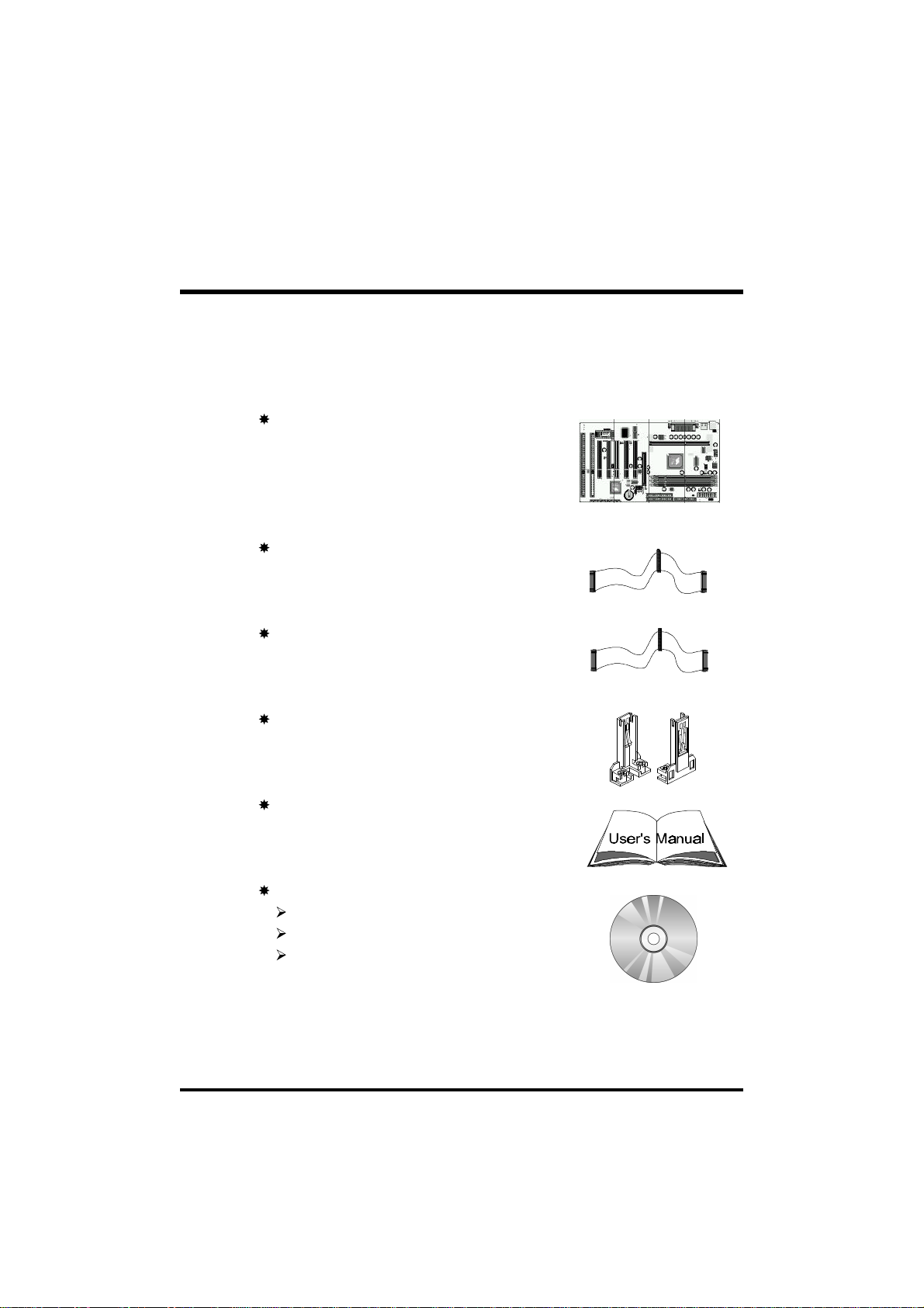
1.2 Item Checklist
Check all items you received with your AV64 mainboard to make sure
nothing is missing. The complete package should include:
One Shuttle AV64 Mainboard
(with onboard Slot1, built-in VIA694X
chipset, ATX form factor, including 2xUSB,
2xSerial, and 1xParallel ports, plus 1xPS/2
Keyboard, and 1xPS/2 Mouse connectors.)
One ATA/66 Ribbon Cable
One Floppy Ribbon Cable
One set of Universal Retention Mechanism
This AV64 User’s Manual
One CD-ROM containing:
The AV64 user’s manual on PDF format
The VIA 4 IN 1 Drivers
The Award Flashing Utility
- 6 -
Page 9

2 FEATURES
The AV64 mainboard is carefully designed for the demanding PC user who wants
high performance and maximum intelligent features in a compact package.
2.1 Specifications
CPU Support
Supports Slot-1 (Celeron, Pentium II/III and Coppermine) processor.
66/100/133MHz CPU Front Side Bus (FSB).
Chipset
Features VIA VT82C694X AGPset with I/O subsystems.
Jumperless CPU Configuration
Auto-detect CPU voltage
Soft-configure CPU Speed (The CPU operating speed is software
configurable in the CMOS Setup menu of the BIOS Setup utility.)
Versatile Memory Support
Equipped with three DIMM banks of PC/100 and PC/133 compliant
SDRAM to provide up to 768MB of system memory.
Configurable support for EC (Error Checking) and ECC (Error Checking
and Correcting).
AGP Slots
AGP V2.0 Compliant
Supports Side Band Addressing (SBA) mode.
Supports 266MHz 4X mode for AD and SBA Signaling.
PCI and ISA Expansion Slots
Provides five 32-bit PCI slots and two 16-bit ISA slots.
LPC Super I/O Onboard
Provides a variety of I/O interfaces:
1 × Floppy interface for 3.5-inch FDD with 720KB, 1.44MB, 2.88MB
- 7 -
Page 10

format or for 5.25-inch FDD with 360KB or 1.2MB format.
1 × PS/2 mouse connector
1 × PS/2 Keyboard connector
2 × USB connectors
2 × DB9 Serial connectors 16550 UART compatible
1 × Infrared communications port ASKIR and HPSIR compatible.
(Serial port COM2 can also be redirected to an external IrDA Adapter
for wireless connection.)
1 × DB25 Parallel port supporting Standard Parallel Port (SPP),
Enhanced Parallel Port (EPP), and Extended Capabilities Port (ECP)
data transmission schemes.
PCI Bus Master IDE Controller Onboard
Two UltraDMA 33/66 Bus Master Dual-channel IDE ports provide support to
a maximum of four IDE devices (one Master and one Slave per channel). The
IDE Bus implements data transfer speeds of up to 66 MB/sec and also supports
Enhanced PIO Modes 3 & 4.
ATX Power Supply Connector
ATX power supply unit can connect to the onboard 20-pin ATX power
connector, supporting Suspend and Soft-On/Off by dual-function power
button.
Advanced Configuration and Power Interface
Features four power savings modes: Snoop, Suspend to RAM, Suspend to
Disk, and Soft-Off. ACPI provides more efficient Energy Savings Features
controlled by your operating system that supports OS Direct Power Management (OSPM) functionality.
System BIOS
Provides licensed Award V4.51PG BIOS on 2MB Flash EEPROM.
Supports Green PC and Desktop Management Interface (DMI).
- 8 -
Page 11

ATX Form Factor
System board conforms to the ATX specification.
Board dimensions: 305mm × 170mm
Advanced Features
Dual Function Power Button - The system can be in one of two states,
one is Suspend mode and the other is Soft-Off mode. Pushing the power
button for less than 4 seconds places the system into Suspend mode.
When the power button is pressed for longer than 4 seconds, the system
enters the Soft-Off mode.
Keyboard/Mouse Power-On - This mainboard implements a special
jumper to enable a system power-on function by keyboard or PS/2 mouse.
Wake-on-LAN (WOL) - The onboard WOL connector can be attached to
a network card that supports this function to wake up the system via the
LAN.
Modem Ring Power-On - The system can be powered on automatically
by activation of the modem ring.
Optional Features
Voltage Monitoring - Monitors various voltages of key elements, such as
the CPU, and other critical system voltage levels to ensure stable current
reach to mainboard components. System voltages include Vcore/ VTT on
CPU, and +5V, +12V, -5V, -12V on system.
Fan Status Monitoring - To prevent overheating of CPU, the CPU fan is
monitored for RPM and failure. (CPU Cooling FAN with RPM sensor is
required.)
- 9 -
Page 12

3 HARDWARE INSTALLATION
This section outlines how to install and configure your AV64 mainboard. Refer to the
following mainboard layout to help you identify various jumpers, connectors, slots, and
ports. Then follow these steps designed to guide you through a quick and correct installation of your system.
3.1 Step-by-Step Installation
Accessories Of AV64
- 10 -
Page 13

Step 1
Install the CPU
1. Mark your CPU Frequency
Checking the working frequency of your cpu that should be clearly
marked on the CPU cover or write your own combination in the space
provided.
2. Pentium II/III Processor Installation
<Locate the Retention Mechanism>
To install a CPU, first turn off your system and remove its cover.
Locate the Retention Mechanism (1) around the Slot 1.
Take care of the Square Cut Mark (1.1).
Fix (1) by inserting Attach Mounts (1.4) up through holes (A1...A4)
in the bottom of the mainboard, and screw the four captive nuts
(1.3).
<Install the CPU>
Insert CPU (2) into the Retention Mechanism (1).
Ensure that the alignment notch in the processor fits over the plug
(1.2), then push processor down firmly until it is seated.
Push the latches (2.1) on the processor outward until they click into
place.
Connect power cable (2.2) of Fan/Heat Sink.
- 11 -
Page 14

3. Celeron Processor Installation
<Locate the Retention Mechanism>
To install a CPU, first turn off your system and remove its cover.
Insert two Retention Mechanism (3) on opposite side of Slot 1.
Fix (3) by inserting Attach Mounts (4) up through holes (A1...A4) in
the bottom of the mainboard, and screw the four captive nuts (3.1).
<Install the CPU>
Hold the processor (5) so that the Heatsink is facing toward the DIMM
sockets on the mainboard.
Slide the processor into the RM. Push the provessor down firmly,
with even pressure on both sides of the top, until it is seated.
- 12 -
Page 15

Step 2.
Set Jumpers
This mainboard is jumperless! The default jumper settings have been set for
the common usage standard of this mainboard. Therefore, you do not need
to reset the jumpers unless you require special adjustments as in any of the
following cases:
1. Over-clock your CPU
2. Clear CMOS
3. Set the wake up function by keyboard/PS2 mouse
For first-time DIY system builders, we recommend that you do not change
the default jumper settings if you are not totally familiar with mainboard
configuration procedures. The factory-set default settings are tuned for
optimum system performance. For the advanced users who wish to customize their system, section 3.2 Jumper Settings will provide detailed information on how to configure your mainboard manually.
Step 3
Install SDRAM System Memory
To install memory, insert SDRAM memory module(s) in any one, two or
three DIMM banks. Note that SDRAM modules are directional and will not
go in the DIMM slots unless properly oriented. After the module is fully
inserted into the DIMM socket, lift the clips of both sides of the DIMM bank
to lock the module in place.
- 13 -
Page 16

Step 4
Install Internal Peripherals in System Case
Before you install and connect the mainboard into your system case, we
recommend that you first assemble all the internal peripheral devices into
the computer housing, including but not limited to the hard disk drive (IDE/
HDD), floppy disk drive (FDD), CD-ROM drive, and ATX power supply
unit. This will greatly facilitate in making the connections to the mainboard
described below.
To install IDE & FDD drives, follow this procedure:
1. Set the required jumpers on each device according to the instructions
provided by the manufacturer. (IDE devices, HDD and CD-ROM, have to
set jumpers to Master or Slave mode depending on whether you install
more than one device of each kind.)
2. Connect IDE cable and FDD cable on the back-panel of the internal
peripheral devices. Note that the cable should be oriented with its
colored stripe (usually red or magenta) connected to pin#1 both on the
mainboard IDE or FDD connector and on the device as well.
3. Connect an available power cable from your system power supply unit
to the back-panel of each peripheral device. Note that the power cable is
directional and cannot fit in if not properly positioned.
- 14 -
Page 17
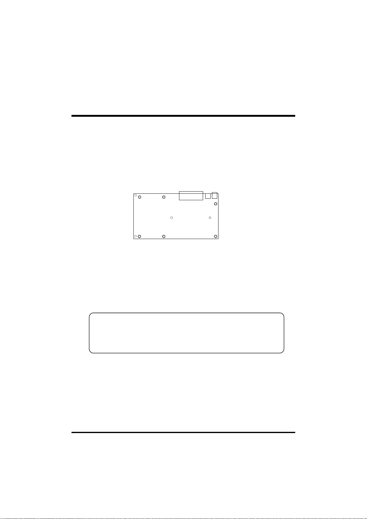
Step 5
Mount the Mainboard on the Computer Chassis
1. You may find that there are a lot of different mounting hole positions
both on your computer chassis and on the mainboard. To choose a
correct mounting hole, the key point is to keep the back-panel of the
mainboard in a close fit with your system case, as shown below.
2. After deciding on the proper mounting holes, position the studs between
the frame of the chassis and the mainboard. The studs are used to fix the
mainboard and to keep a certain distance between the system chassis
and the mainboard, in order to avoid any electrical shorts be tween the
board and the metal frame of the chassis. (If your computer case is
already equipped with mounting studs, you will need to tighten screws to
attach the mainboard.)
Note: In most computer housings, you will be able to find 4 or more
attachment points to install mounting studs and fix the mainboard.
If there aren’t enough matching holes, then make sure to install at
least 3 mounting studs to ensure proper attachment of the
mainboard.
- 15 -
Page 18
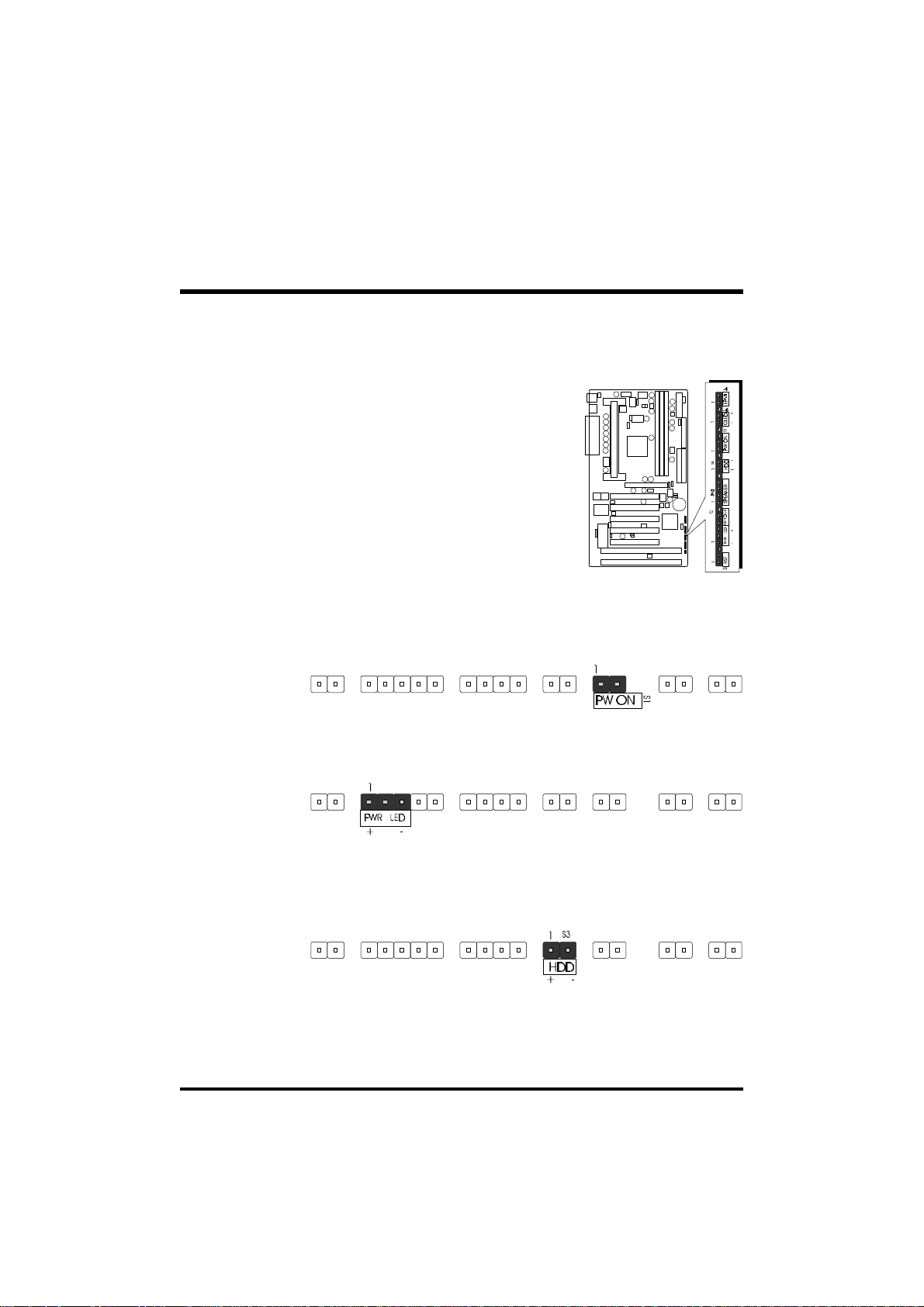
Step 6
Connect Front Panel Switches/LEDs/Speaker
You can find there are several different
cables already existing in the system
case and originating from the computer’s
front-panel devices (HDD LED, Power
LED, Reset Switch, PC Speaker, etc.)
These cables serve to connect the
front-panel switches and LEDs to the
mainboard’s front-panel connectors
group, as shown below.
1. ATX Soft Power On/Off
2. Power-LED
3. HDD-LED
- 16 -
Page 19

4. EPMI
(Hardware System Management Interface)
5. Green-LED
6. PC Speaker
7. Hardware Reset Switch
8. Keylock
- 17 -
Page 20
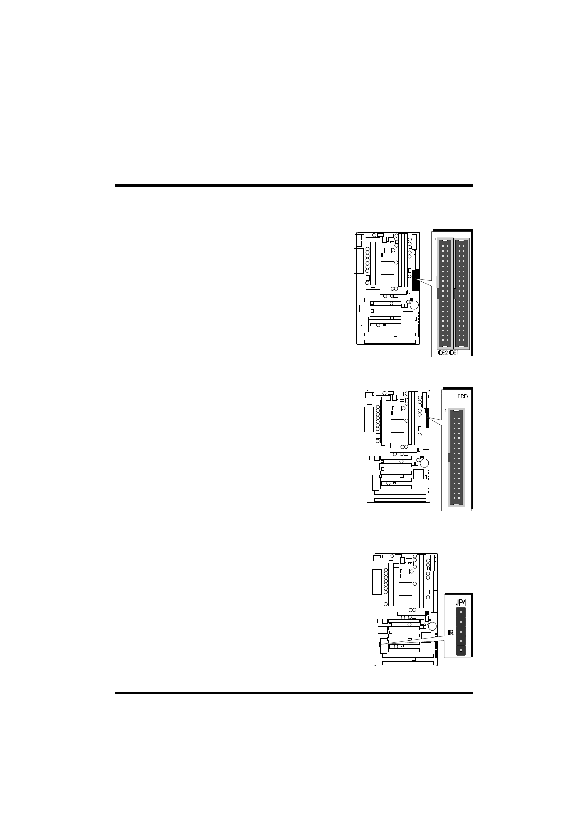
Step 7
Connect IDE & Floppy Disk Drives
1. IDE cable connector
2. FDD cable connector
Step 8
Connect Other Internal Peripherals
1. IR connector
- 18 -
Page 21
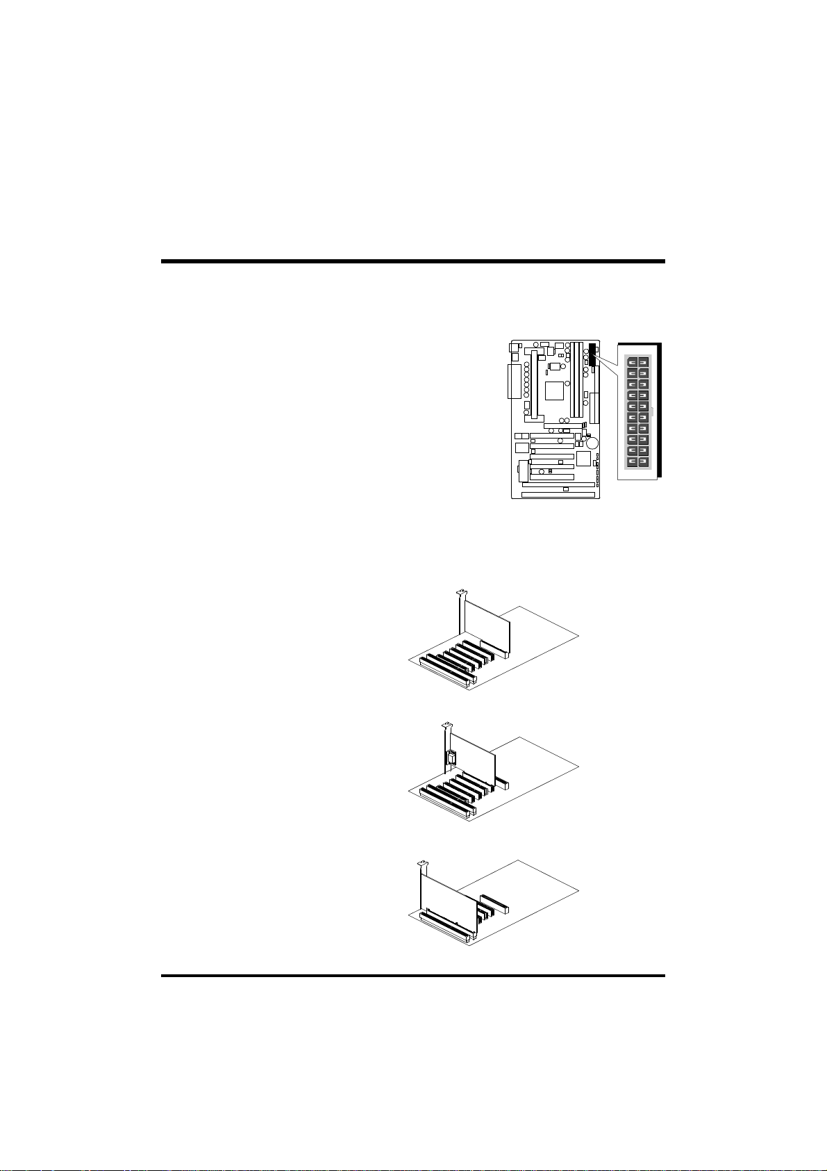
Step 9
Connect the Power Supply
1. System power connector
Step 10
Install Add-on Cards in Expansion Slots
1. Accelerated Graphics Port (AGP) Card
2. PCI Card
3. ISA Card
- 19 -
Page 22

Step 11
Connect External Peripherals to Back Panel
You are now ready to put the computer case back together and get on to the
external peripherals connections to your system’s back-panel.
1.PS/2 Mouse and Keyboard
2.USB Devices
3. Parallel Port
4.COM Ports
PS/2 Mouse
PS/2 keyboard
USB1 & USB2
Parallel Port
COM12COM2
- 20 -
Page 23

Step 12
First Time System Boot Up
To assure the completeness and correctness of your system installation, you
may check the above installation steps once again before you boot up your
system for the first time.
1. Insert a bootable system floppy disk (DOS 6.2x, Windows 95/98/NT, or
others) which contains FDISK and FORMAT utilities into the FDD.
2. Turn on the system power.
3. First, you must use the FDISK utility to create a primary partition of the
hard disk. You can also add an extended partition if your primary partition does not use all of the available hard disk space. If you choose to
add an extended partition, you will have to create one or more logical
partitions to occupy all the space available to the extended partition. The
FDISK utility will assign a drive letter (i.e., C:, D:, E:,...) to each partition
which will be shown in the FDISK program. After FDISK procedure,
reboot your system by using the same system floppy disk.
Note: DOS 6.2x and Windows 95A can only support up to 2.1GB of
HDD partition. If you use the FDISK utility with one of the
operating systems mentioned above, you can only device your
HDD into partitions no larger than 2.1GB each.
4. Now, use the FORMAT utility to format all the partitions you’ve created.
When formatting the primary partition (C:), make sure to use the
FORMAT C: /S command.
Note: FORMAT C: /S can transfer all the necessary system files into the
primary partition of your hard disk. Then, your HDD will become
a bootable drive.
5. Install all the necessary drivers for CD-ROM, Mouse, etc.
6. Setup the complete operating system according to your OS installation
guide.
- 21 -
Page 24

Step 13
Install Drivers & Software Components
Please note that all the system utilities and drivers are designed for Win 9x
operating systems only. Make sure your Windows 9x operating system is
already installed before running the drivers installation CD-ROM programs.
1.Insert the AV64 bundled CD-ROM into your CD-ROM drive. The
auto-run program will display the drivers main installation window on
screen.
2.Select the Mainboard related program.
3.Install AV64 Driver for Win9x/Win NT.
- 22 -
Page 25

3.2 Jumper Settings
Several hardware settings are made through the use of jumper caps to
connect jumper pins on the mainboard. Pin #1 is located on the bottom
or on the left when holding the mainboard with the keyboard connector
or other back-panel connectors opposite from you, as shown below.
3-pin and multi (>3) pin jumpers show as follows:
Pin #1 on the left:
Pin #1 on the bottom:
Jumpers with two pins are shown as for Close [On] or for
Open [Off]. To Short jumper pins, simply place a plastic jumper cap over
the desired pair of pins.
Caution!
1. Do not remove the mainboard from its antistatic protective packaging
until you are ready to install it.
2. Carefully hold the mainboard by its edges and avoid touching its
components. When putting the mainboard down, place it on top of its
original packaging film, on an even surface, and components side up.
3. Wear an antistatic wrist strap or take other suitable measures to prevent
electrostatic discharge (ESD) whenever handling this equipment.
- 23 -
Page 26
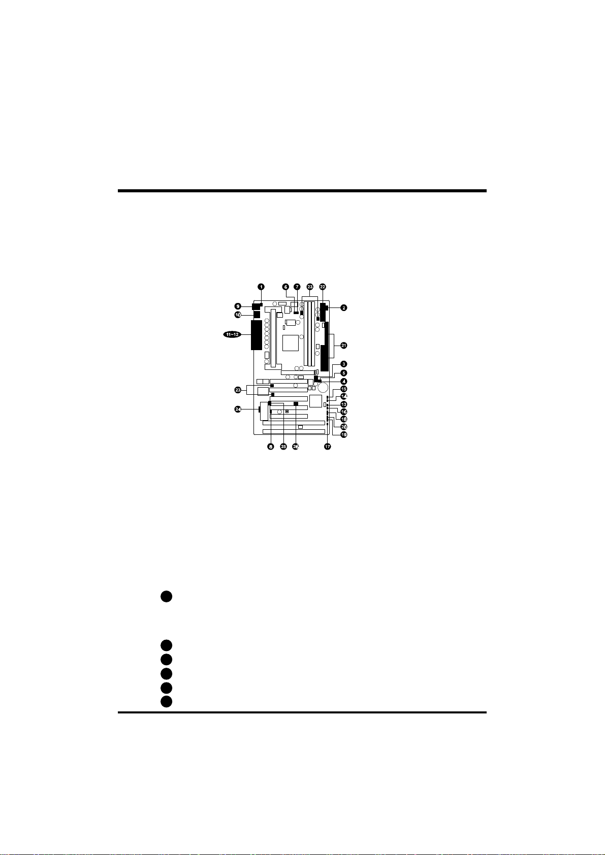
Jumpers & Connectors Guide
Use the mainboard layout on page 10 to locate CPU socket, memory banks,
expansion slots, jumpers and connectors on the mainboard during the installation. The following list will help you identify jumpers, slots, and connectors along with their assigned functions:
CPU/Memory/Expansion Slots
Slot 1 : CPU Slot for Pentium II/III, Celeron processors
J5, J3, J4 : Three DIMM Sockets for 8,16,32,64,128,256MB 3.3V
SDRAM
AGP : One AGP (Accelerated Graphics Port) Slot
PCI : Five 32-bit PCI Expansion Slots
ISA : Two 16-bit ISA Expansion Slots
Jumpers
1
JP38 : Keyboard & PS/2 Mouse Power-On
(requires to always set JP38 jumper in order to enable either
or both KB & PS/2 mouse power-on functions. In addition,
you need to set Power On Function in BIOS setup.)
2
JP39 : CPU Host frequency setting
3
JP37 : CPU Clock Ratio setting
4
JP19 : Clear CMOS
5
JP32 : ICH Voltage setting
6
JP48 : CPU Vcore Fine tune setting
- 24 -
Page 27

7
J55 & JP45 : Over-Clocking the CPU
8
J44 : BIOS Top Block Lock
Back Panel Connectors
9
KB : PS/2 Keyboard
9
MS : PS/2 Mouse
USB : 2 × USB (Universal Serial Bus)
10
COM1 : Serial Port 1 (DB9 male)
11
11
COM2 : Serial Port 2 (DB9 male)
12
PRINTER : Parallel Port (DB25 female)
Front Panel Connectors
PWON (S1) : ATX Power On/Off Momentary Type Switch
13
GLED (J48) : Green LED (ON when system in power savings mode)
14
EPMI (J42) : Hardware System Management Interface Momentary
15
Type switch.
HDD (S3) : IDE Drive Active LED
16
RST (J32) : Hardware Reset Switch
17
SPEAKER (JP24) : Housing Internal Speaker
18
PWR LED (J27) : System Power LED
19
KEYLOCK (J27): Keylock
20
Internal Peripherals Connectors
FDD : Floppy Disk Drive Interface
21
IDE1 : IDE Primary Interface (Dual-channel)
21
IDE2 : IDE Secondary Interface (Dual-channel)
21
Other Connectors
22
CPU FAN (JP29): CPU Cooling Fan Power
23
23
FAN (JP28) : Housing Cooling Fan Power
23
FAN (J43) : Housing Cooling Fan Power
23
FAN (J47) : Housing Cooling Fan Power
24
JP4 : IR Connector
25
J45 : Wake-On-LAN Connector
JP46 : SB-LINK Connector
26
: ATX Power (20-pin header)
- 25 -
Page 28

1
Set Keyboard & PS/2 Mouse Power-On (JP38)
AV64 mainboard provides an easy power-on by keyboard and PS/2 mouse.
Note: When you enable Keyboard Power-On, you also need to configure
the proper hot-key combination <Ctrl> + < function key F1 ~
F12 > in BIOS setup program.
To Power on the system by keyboard, simply strike the proper hot-key.
(A hot-key is the combination of <Ctrl> + <configured function key
F1 ~ F12>)
To power on the system by PS/2 mouse, you only need to double-click with
the mouse. (Note that power-on by serial mouse is not supported)
To enable/disable either or both keyboard and PS/2 mouse power-on functions, follow the steps outlined below:
JP38 1-3, 4-6 (default)
Step 1. Adjust the jumper group JP38 as shown in the following table.
K/B & PS/2 M ouse Power-On - JP38
Keyboard &
PS/2 Mouse
Power-On Disabled
Keyboard &
PS/2 Mouse
Power -On Enabled
Keyboard
Power-On Enabled
PS/2 Mouse
Power-On Enabled
Step 2. Set the Power On field to the proper value (Hot-key or PS/2
Mouse) in Integrated Peripherals menu of BIOS setup.
- 26 -
Page 29
2
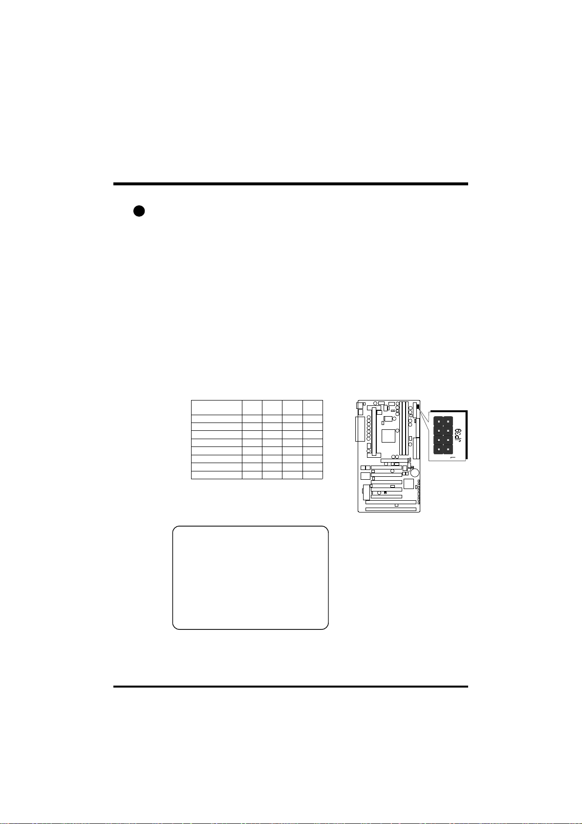
CPU Host Frequency hardware Setting (JP39)
Normally, CPU FSB auto-detecting by BIOS, System wil assign
proper frequency to CPU, when JP39 set to default position.
We strongly advise novice users not to modify the original setting of the
CPU host frequency, for setting an incorrect value may damage your CPU.
For experienced users, the AV64 mainboard provides an alternative HardConfigure function to adjust your CPU host frequency manually.
Insert mini-jumper caps properly on JP39 to reach desired CPU
Host Frequency, as shown in the following table.
System Clock
(JP39)
66 MHz OFF OFF ON ON
75 MHz ON OFF ON ON
83 MHz OFF ON ON ON
100 MHz OFF OFF OFF ON
112 MHz ON OFF OFF ON
133 MHz (Default) OFF OFF OFF OFF
140 MHz ON ON OFF OFF
150 MHz ON OFF OFF OFF
1-2 3-4 5-6 7-8
Note:75, 83 MHz are over-clock
usage for 66MHz base processor,
112~103MHz are over-clock
usage for 100MHz base processor,
and 140MHz~150MHz are overclock usage for 133 MHz base
processor. However, over-clocking
is not a recommended practice.
- 27 -
Page 30

3
CPU Clock Ratio Setting (JP37)
AV64 mainboard provides a jumper group JP37 to set CPU speed
configure by BIOS or by hardware jumper.
By inserting jumper pack on Auto group, the user can Soft-Configure the
CPU Host Frequency and CPU Clock Ratio from BIOS.
By removing jumper pack from Auto group and inserting mini jumpers
on Manual group properly, the user can configure the CPU Clock Ration
manually.
Processor
System Clock
JP39
Multiplier
JP37
Processor
System Clock
JP39
Multiplier
JP37
Multiplier
(JP37 )
1-2 3-4 5-6 7-8
(66 )
MHz
(100)
MHz
3.5X ON OFF ON OFF 233 350
4X OFF ON ON ON 266 400 533
4.5X OFF ON ON OFF 300 450 600
5X OFF OFF ON ON 333 500 667
5.5X OFF OFF ON OFF 366 550 733
6X ON ON OFF ON 400 600
6.5X ON ON OFF OFF 433 650
7X ON OFF OFF ON 466 700
7.5X ON OFF OFF OFF 500 750
8X OFF ON OFF ON 800
233 MHz
(66MHz x 3.5)
350 MHz
(100MHz x 3.5)
266 MHz
(66MHz x 4)
400 MHz
(100MHz x 4)
300 MHz
(66MHz x 4.5)
450 MHz
(100MHz x 4.5)
333 MHz
(66MHz x 5)
500 MHz
(100MHz x 5)
(133)
MHz
366 MHz
(66MHz x 5.5)
550 MHz
(100MHz x 5.5)
400 MHz
(66MHz x 6)
600 MHz
(100MHz x6)
433 MHz
(66MHz x 6.5)
600 MHz
(133MHz x4.5)
466 MHz
(66MHz x7)
667 MHz
(133MHz x5)
500 MHz
(66MHz x 7.5)
733 MHz
(133MHz x5.5)
- 28 -
Page 31
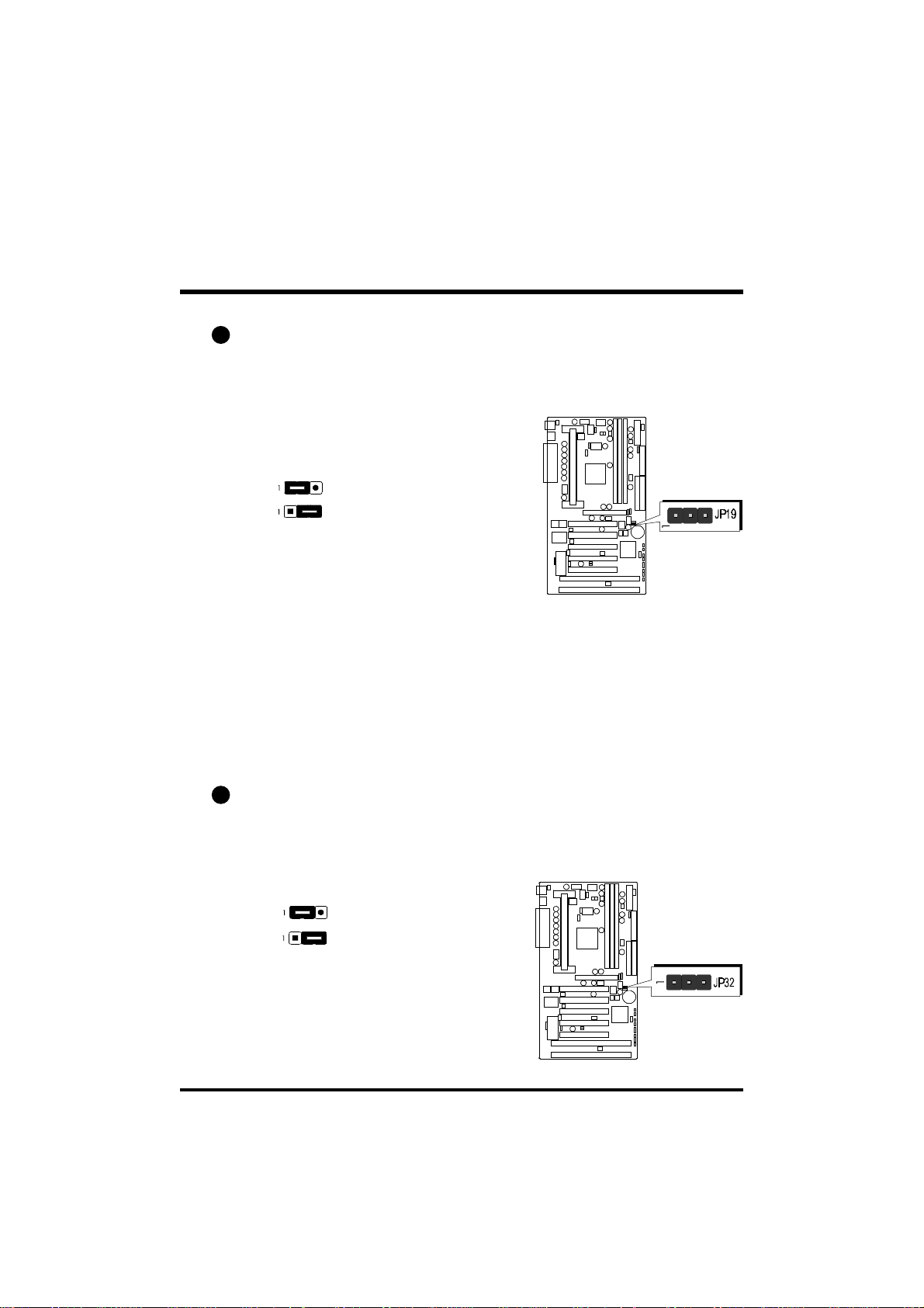
4
Clear CMOS (JP19)
JP19 is used to clear CMOS data. Clearing CMOS will result in permanently erasing the previous system configuration settings and restoring the
original (factory-set) system settings.
Pin 1-2 (Default)
Pin 2-3 (Clear CMOS)
Step 1. Turn off the system power (PC-> Off)
Step 2. Remove jumper cap from JP19 pins 1-2
Step 3. Place the jumper cap on JP19 pin 2-3
for a few seconds
Step 4. Return the jumper cap to pin 1-2
Step 5. Turn on the system power (PC-> On)
5
ICH Voltage Setting (J32)
This jumper allows you to select the voltage supplied to the VT82C596B.
The default voltage should be used unless some IDE devices need more
voltage supplied.
Pin 1-2 (3.6V)
Pin 2-3 (3.3V) default
- 29 -
Page 32
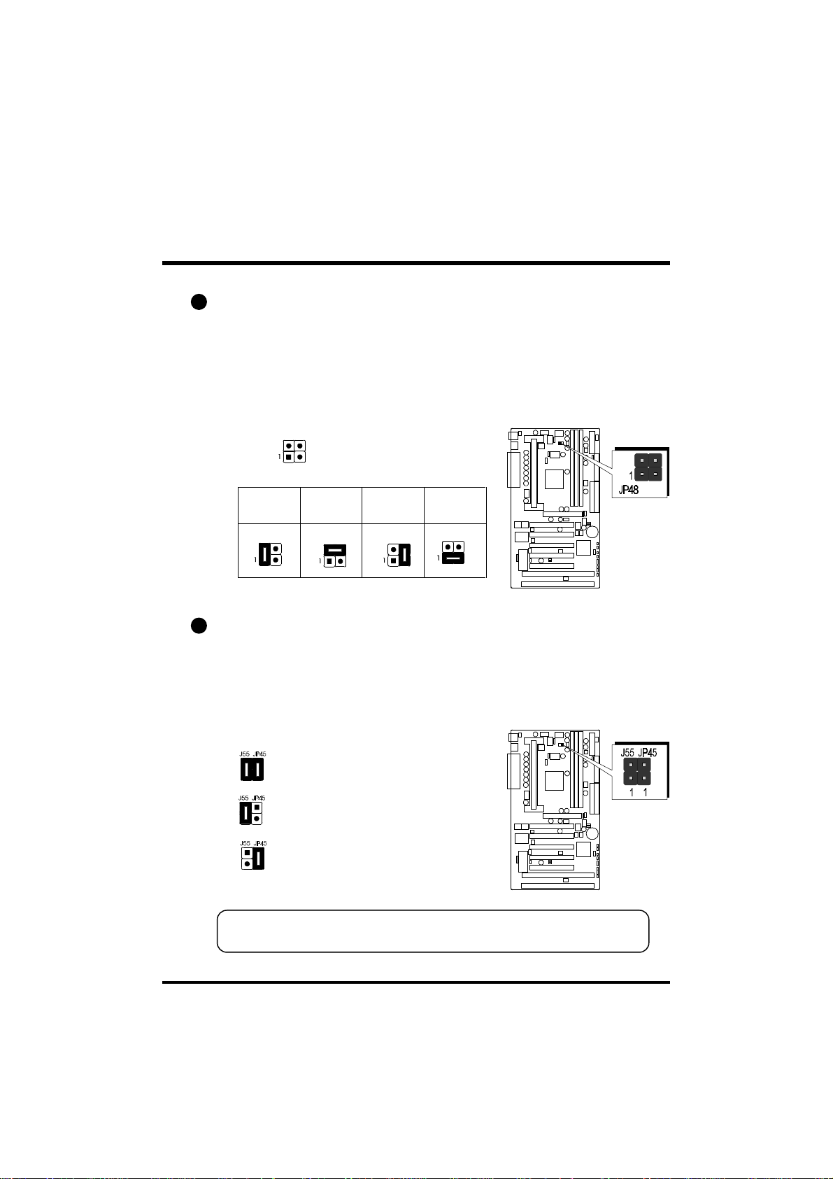
6
CPU Vcore Fine tune (JP48)
The CPU voltage setting is jumperless. This means that your AV64
mainboard can detect the CPU voltage automatically; therefore, you do not
need to configure any voltage jumper.
But, AV64 provide an extra 4-pin jumper to increase CPU core voltage for
overspeed usage.
JP48 All open (default)
Increase
0.15% CPU
Core Voltage
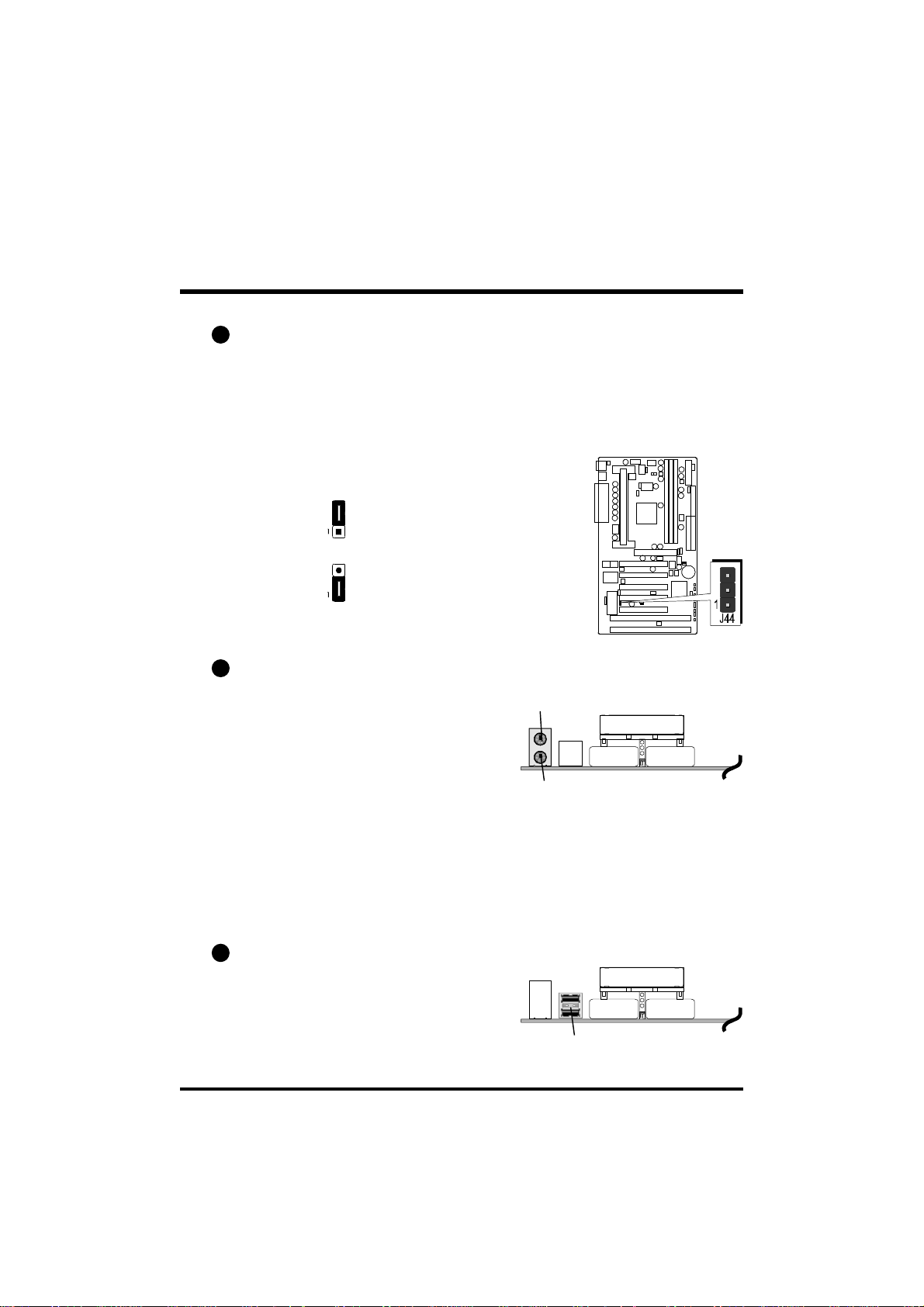
7
Over-Clocking the CPU (J55 & JP45)
Increase
0.5% CPU
Core Voltage
Increase
1.5% CPU
Core Voltage
Increase
7.8% CPU
Core Voltage
AV64 mainboard provides two special jumpers J55 to over-clock FSB up to
100MHz and JP45 to over-clock FSB up to 133MHz when CPU configuration performed by hard-configure.
J55, JP45 Close (default)
J55 Close (over-clock to 100MHz)
JP45 Close (over-clock to 133MHz)
Warning : Over-clocking is not a recommended practice for it may
damage both the mainboard and the processor.
- 30 -
Page 33
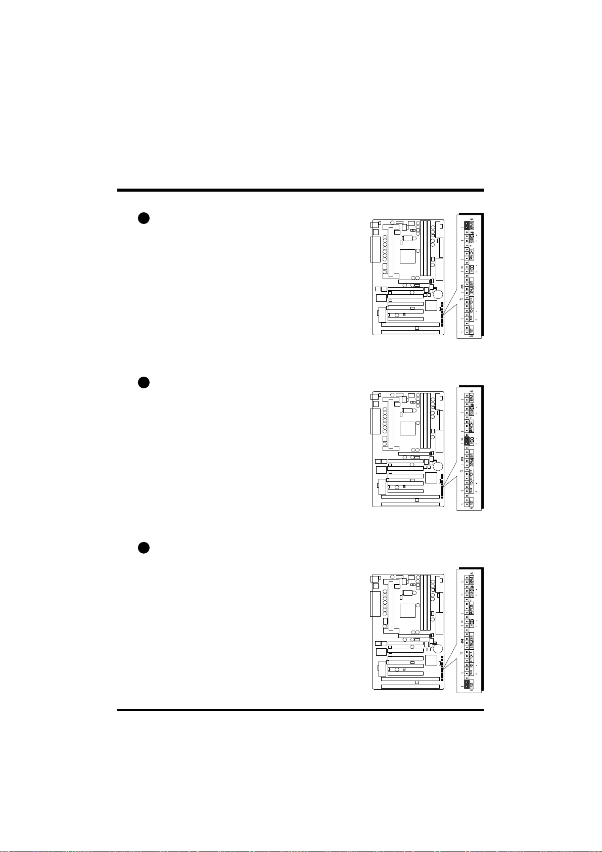
8
Boot-Block Protection (J44)
J44 is used protect the Boot-Block in BIOS. If the virus infects the BootBlock section, your system will not be able to boot forever. You may
choose close J44 pins 1-2 for Boot-Block protection; however, please close
J44 pins 2-3 if yu need to reflash the BIOS. A protected Boot-Block
may cause your BIOS reflash failed.
Pin 2-3 (default)
Flash All Block
Pin 1-2
Top Block Lock
9
PS/2 Keyboard & PS/2 Mouse Connectors
Two 6-pin female PS/2 keyboard &
Mouse connectors are located at the
rear panel of the mainboard. Depending on the computer housing you use
(desktop or minitower), the PS/2 Mouse
connector is situated at the top of the
PS/2 Keyboard connector when the
mainboard is laid into a desktop, as opposed to a minitower where the PS/2
Mouse connector is located at the right
of the PS/2 Keyboard's. Plug the PS/2
keyboard and mouse jacks into their
corresponding connectors.
PS/2 Mouse
PS/2 keyboard
10
USB1/USB2 Port Connectors
Two female connectors USB1/USB2
share the same USB (Universal Serial
Bus) bracket at the rear panel of your
mainboard. Plug each USB device jack
into an available USB1/USB2 connector.
USB1 & USB2
- 31 -
Page 34

11
COM1 / COM2 Connector
This mainboard can accommodate two
serial device on COM1/COM2 .
Attach a serial device cable to the DB9
serial port COM1/COM2 at the back
panel of your computer.
12
Parallel Port Connector
One DB25 female parallel connector
is located at the rear panel of the
mainboard. Plug the connection cable
from your parallel device (printer, scanner, etc.) into this connector.
13
ATX Power On/Off Switch Connector (PWON - S1)
The Power On/Off Switch is a momentary type switch used for turning on or off
the system’s ATX power supply. Attach
the connector cable from the Power
Switch to the 2-pin PWON header on the
mainboard.
Note :Please notice the Speaker
and all the LED connector is
directional.If your chassis’s
LED does not light during
running, please simply
change to the opposite
direction.
COM12COM2
Parallel Port
14
Green LED Connector (GLED - J48)
The Green LED (GLED) indicates that the
system is currently in one of the power
savings mode (Doze/Standby/Suspend).
When the system resumes to normal
operation, mode, the Green LED will go
off. Attach a 2-pin Green LED cable to
GLED header.
- 32 -
Page 35
15
EPMI Connector (EPMI - J42)
Hardware System Management Interface
(EPMI) header may attach to a 2-pin momentary switch. Press the EPMI switch to
force the system into power savings mode;
press again to resume normal operation.
16
HDD LED Connector (HDD - S3)
Attach the connector cable from the IDE
device LED to the 2-pin HDD LED header.
The HDD LED lights up whenever an IDE
device is active.
17
Hardware Reset Connector (RST - J32)
Attach the 2-pin hardware reset switch
cable to the RST header. Pressing the
reset switch causes the system to restart.
- 33 -
Page 36

Speaker Connector (SPEAKER - JP24)
18
Attach the PC speaker cable from the case
to the 4-pin speaker connector (SPK).
19
PWR LED Connector (PWR LED- J27)
Attach the 3-pin Power-LED connector
cable from the housing front panel to the
PWR header on the mainboard. The
power LED stays lit while the system is
running.
20
Keylock Connector (KEYLOCK - J27)
Attach the 2-pin Power-LED connector
cable from the housing front panel to the
PWR header on the mainboard. The
power LED stays lit while the system is
running.
- 34 -
Page 37

21
Enhanced IDE Ports and Floppy Connectors
The AV64 mainboard features two 40-pin dual-channel IDE device connectors (IDE1/IDE2) providing support for up to four IDE devices, such as CDROM and Hard Disk Drives (H.D.D.). This mainboard also includes one
34-pin floppy disk controller (FDC) to accommodate the Floppy Disk Drive
(F.D.D.). Moreover, this mainboard comes with one 40pin ribbon cable to
connect to IDE H.D.D. and one 34-pin ribbon cable for F.D.D. connection.
Note : Please connect your
system H.D.D. on IDE 1.
Important: Ribbon cables are directional,
therefore, make sure to always
connect with the red cable
stripe on the same side as pin
#1 of the IDE1/IDE2 or FDC
connector on the mainboard.
22
ATX Power Supply Connector
Locate the 20-pin male header ATX power connector on your mainboard.
Plug the power cable from the ATX power supply unit directly into ATX
power supply connector.
Note 1: The ATX power connector is directional and will not go in unless
the guides match perfectly making sure that pin#1 is properly
positioned.
Note 2: Make sure the latch of the ATX power connector clicks into place
to ensure a solid attachment.
Note 3: This mainboard requires an ATX power supply of at least 200 watts
with power good signal.
- 35 -
Page 38

23
Cooling Fan Connectors for CPU (JP29), Chassis (JP28),
(J43) & (J47)
The mainboard provides four onboard 12V cooling fan power connectors to
support CPU (JP29), Chassis (JP28), (J43) and (J47) cooling fans.
Note: Both cable wiring and type of plug may vary depending
on the fan maker. Keep in mind that the red wire should
always be connected to the +12V header and the black
wire to the ground (GND) header.
24
IR Connector (JP4)
If you have an Infrared device, this mainboard can implement IR transfer
function. To enable the IR transfer function, follow these steps:
IR Pin Assignments:
1=VCC
2=CIRRX
3=IRRX
4=Ground
5=IRTX
Step 1. Attach the 5-pin infrared device cable to JP4 connector.
(Refer to the above diagram for IR pin assignment.)
Step 2. Configure the Infrared transfer mode in the UR2 Mode field of
integrated Peripherals menu in BIOS Setup. This mainboard
supports IrDA, ASKIR, Normal and SCR transfer modes.
- 36 -
Page 39
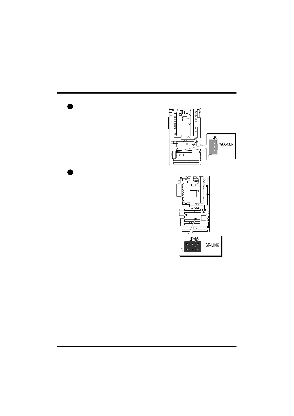
25
Wake-on LAN Connector (J45)
Attach a 3-pin connector from the LAN
card which supports the Wake-On-LAN
(WOL) function. This function lets users
wake up the connected system through
the LAN card.
26
SB-Link Connector (JP46)
The main board provides a 2x3 pin SBLink header accepts the Creative CT4600
series PCI sound cards with PCI solution
to connect the legacy Sound Blaster compatible audio to the PCI bus.
- 37 -
Page 40

3.3 System Memory Configuration
The AV64 mainboard has three 168-pin DIMM sockets that allow you to
install from 16MB up to 768MB of system memory with SDRAM (Synchronous DRAM). Each DIMM (Dual In-line Memory Module) socket can
accommodate 16MB, 32MB, 64MB, 128MB, and 256MB 3.3V single or
double side SDRAM modules. DIMM sockets are arranged in two banks,
each memory bank made of one socket and providing a 64 bit wide data
path.
The AV64 mainboard supports data integrity algorithms including EC (Error
Checking) and ECC (Error Checking and Correction) in the memory array.
In EC mode, single and multiple bit error detection is provided. In ECC
mode, when the memory is being read from DRAM, the AV64 provides
both error checking and correction of the data.
Install Memory:
Install memory in any or all of the banks and in any combination, as follows.
DIMM
Socket
DIMM 1
DIMM 2
DIMM 3
Memory Modules
16MB, 32MB, 64MB, 128MB, 256MB 168-pin
3.3V SDRAM DIMM
16MB, 32MB, 64MB, 128MB, 256MB 168-pin
3.3V SDRAM DIMM
16MB, 32MB, 64MB, 128MB, 256MB 168-pin
3.3V SDRAM DIMM
Module
Quantity
x 1
x 1
x 1
Note: You do not need to set any jumper to configure memory since the
BIOS utility can detect the system memory automatically. You can
check the total system memory value in the BIOS Standard CMOS
Setup menu.
Upgrade Memory:
You can easily upgrade the system memory by inserting additional SDRAM
modules in available DIMM banks. The total system memory is calculated
by simply adding up the memory in all DIMM banks. After upgrade, the
new system memory value will automatically be computed and displayed
by the BIOS Standard CMOS Setup menu.
- 38 -
Page 41

4 SOFTWARE UTILITY
4.1 AV64 Mainboard CD Overview
Note: The AV64 mainboard attachment CD contents are subject to change
without notice.
To start your mainboard CD disc, just insert it into your CD-ROM drive and
the CD AutoRun screen should appear. If the AutoRun screen does not
appear, double click or run D:\Autorun.exe (assuming that your CD-ROM
drive is drive D:)
Navigation Bar Description:
Install Mainboard Software - Installing AV64 Mainboard
Drivers for Windows
Manual - AV64 series mainboard user's manual in PDF format.
Link to Shuttle Homepage - Link to shuttle website homepage.
Browse this CD - Allows you to see the contents of this CD.
Quit - Close this CD.
- 39 -
Page 42

4.2 Install Mainboard Driver
Insert the attachment CD into your CD-ROM drive and the CD AutoRun
screen should appear. If the AutoRun screen does not appear, double click
on Autorun icon in My Computer to bring up Shuttle Mainboard Software
Setup screen.
Select using your pointing device (e.g. mouse) on the “Install Mainboard
Software” bar.
Once you made your selection, a Setup window which automatically
runs the installation.
When the files are done copying make sure you reboot the system to
insure that the files are installed correctly.
- 40 -
Page 43

4.3 To View the User's Manual
Insert the attachment CD into your CD-ROM drive and the CD AutoRun
screen should appear. If the AutoRun screen does not appear, double click
on Autorun icon in My Computer to bring up Shuttle Mainboard Software
Setup screen.
Select using your pointing device (e.g. mouse) on the “Manual” bar.
Then Online Information windows will appear on your screen. Click on
the “Install Acrobe Reader 3.0” bar if you need to install acrobe reader.
Then click on "AV64 Manual" bar to view AV64 user's manual.
- 41 -
Page 44

5 BIOS SETUP
AV64 BIOS ROM has a built-in Setup program that allows users to modify
the basic system configuration. This information is stored in
battery-backed RAM so that it retains the Setup information even if the
system power is turned off.
The system BIOS is managing and executing a variety of hardware related
functions in the system, including:
System date and time
Hardware execution sequence
Power management functions
Allocation of system resources
5.1 Entering BIOS
To enter the BIOS (Basic Input / Output System) utility, follow these steps:
Step 1. Power on the computer and the system will perform its
POST (Power-On Self Test) routine checks.
Step 2. Press <Del> key immediately or at the following message:
“Press DEL to enter SETUP”
or simultaneously press <Ctrl>, <Alt>, <Esc> keys
Note 1. If you miss the train (the message disappears before you can
respond) and you still wish to enter BIOS Setup, restart the system
and try again by turning the computer OFF and ON again or by
pressing the <RESET> switch located at the computer’s front
panel. You may also reboot by simultaneously pressing the
<Ctrl>, <Alt>, <Del> keys.
Note 2. If you do not press the keys in time and system does not boot, the
screen will prompt an error message and you will be given the
following options:
“Press F1 to Continue, DEL to Enter Setup”
Step 3. As you enter the BIOS program, the CMOS Setup Utility will
prompt you the Main Menu, as shown in the next section.
- 42 -
Page 45

5.2 The Main Menu
Once you enter the AwardBIOS(tm) CMOS Setup Utility, the Main
Menu will appear on the screen. The Main Menu allows you to select
from several setup functions and two exit choices. Use the arrow keys
to select among the items and press <Enter> to accept and enter the
sub-menu.
Note that a brief description of each highlighted selection appears at
the bottom of the screen.
Setup Items
The main menu includes the following main setup categories. Recall
that some systems may not include all entries.
Standard CMOS Features
Use this menu for basic system configuration.
Advanced BIOS Features
Use this menu to set the Advanced Features available on your system.
Advanced Chipset Features
Use this menu to change the values in the chipset registers and optimize your system's performance.
- 43 -
Page 46

Integrated Peripherals
Use this menu to specify your settings for integrated peripherals.
Power Management Setup
Use this menu to specify your settings for power management.
PnP / PCI Configuration
This entry appears if your system supports PnP / PCI.
PC Health Status (optional features)
This entry shows the current system temperature, Voltage and FAN
speed.
Frequency/Voltage Control
Use this menu to specify your settings for frequency/voltage control.
Load Fail-Safe Defaults
Use this menu to load the BIOS default values for the minimal/stable
performance for your system to operate.
Load Optimized Defaults
Use this menu to load the BIOS default values that are factory settings
for optimal performance system operations. While Award has designed the custom BIOS to maximize performance, the factory has the
right to change these defaults to meet their needs.
Supervisor / User Password
Use this menu to set User and Supervisor Passwords.
Save & Exit Setup
Save CMOS value changes to CMOS and exit setup.
Exit Without Saving
Abandon all CMOS value changes and exit setup.
- 44 -
Page 47

Standard CMOS Setup
The items in Standard CMOS Setup Menu are divided into 10 categories. Each category includes no, one or more than one setup items.
Use the arrow keys to highlight the item and then use the <PgUp>
or <PgDn> keys to select the value you want in each item.
Date
<Month> <DD> <YYYY>
Set the system date. Note that the 'Day' automatically changes when
you set the date.
Time
<HH : MM : SS>
Set the system time.
IDE Primary Master
Options are in its sub menu.
Press <Enter> to enter the sub menu of detailed options.
IDE Primary Slave
Options are in its sub menu.
Press <Enter> to enter the sub menu of detailed options.
- 45 -
Page 48

IDE Secondary Master
Options are in its sub menu.
Press <Enter> to enter the sub menu of detailed options.
IDE Secondary Slave
Options are in its sub menu.
Press <Enter> to enter the sub menu of detailed options.
Drive A/Drive B
Select the type of floppy disk drive installed in your system.
The choice: None, 360K, 5.25 in, 1.2M, 5.25 in, 720K, 3.5 in,
1.44M, 3.5 in, 2.88M, 3.5 in
Video
Select the default video device.
The choice: EGA/VGA, CGA 40, CGA 80, MONO
Halt On
Select the situation in which you want the BIOS to stop the POST
process and notify you.
The choice: All Errors, No Errors, All, but Keyboard, All, but Dis
kette, All, but Disk/Key
Base Memory
Displays the amount of conventional memory detected during boot up.
The choice: N/A
Extended Memory
Displays the amount of extended memory detected during boot up.
The choice: N/A
Total Memory
Displays the total memory available in the system.
The choice: N/A
- 46 -
Page 49

******************************************************
IDE Adapters
The IDE adapters control the hard disk drive. Use a separate sub
menu to configure each hard disk drive.
IDE HDD Auto-detection
Press Enter to auto-detect the HDD on this channel. If detection is
successful, it fills the remaining fields on this menu.
Press Enter
IDE Primary Master
Selecting 'manual' lets you set the remaining fields on this screen.
Selects the type of fixed disk. "User Type" will let you select the
number of cylinders, heads, etc. Note: PRECOMP=65535 means
NONE !
The choice: None, Auto, Manual.
Access Mode
Choose the access mode for this hard disk.
The choice: Normal, LBA, Large, Auto.
Capacity
Disk drive capacity (Approximated). Note that this size is usually
slightly greater than the size of a formatted disk given by a disk checking program.
Auto Display your disk drive size.
The following options are selectable only if the 'IDE Primary Master'
item is set to 'Manual'
Cylinder
Set the number of cylinders for this hard disk.
Min = 0, Max = 65535
Head
Set the number of read/write heads.
Min = 0, Max = 255
- 47 -
Page 50

Precomp
Warning: Setting a value of 65535 means no hard disk.
Min = 0, Max = 65535
Landing zone
Set the Landing zone size.
Min = 0, Max = 65535
Sector
Number of sectors per track.
Min = 0, Max = 255
******************************************************
- 48 -
Page 51

Advanced BIOS Features
This section allows you to configure your system for basic operation.
You have the opportunity to select the system's default speed, boot-up
sequence, keyboard operation, shadowing and security.
Virus Warning
Allows you to choose the VIRUS Warning feature for IDE Hard Disk
boot sector protection. If this function is enabled and someone attempt to write data into this area, BIOS will show a warning message
on screen and alarm beep.
Enabled Activates automatically when the system boots up
causing a warning message to appear when anything
attempts to access the boot sector or hard disk partition table.
Disabled No warning message will appear when anything
attempts to access the boot sector or hard disk partition table.
The choice: Enabled, Disabled.
CPU Internal Cache
This item enables CPU external cache to speed up memory access.
The choice: Enabled, Disabled.
- 49 -
Page 52

CPU Internal Cache
This item enables CPU secondary cache to speed up memory access.
The choice: Enabled, Disabled.
CPU L2 Cache ECC Checking
When you select Enabled, memory checking is enable when the
external cache contains ECC SRAMs.
The choice: Enabled, Disabled.
Processor Number Feature
Allows you to Enabled/Disabled, the processor serial number.
The choice: Enabled, Disabled.
Quick Power On Self Test
This item speeds up Power On Self Test (POST) after you power on the
computer. If it is set to Enabled, BIOS will shorten or skip some check
items during POST.
The choice: Enabled, Disabled.
First/Second/Third Boot Device
The BIOS attempts to load the operating system from the devices in
the sequence selected in these items.
The Choice: Floppy, LS/ZIP, HDD-0, SCSI, CDROM, HDD-1,
HDD-2, HDD-3, LAN, Disabled.
Boot Other Device
Select Your Boot Device Priority.
The Choice: Enabled, Disabled.
Swap Floppy Drive
If the system has two floppy drives, you can swap the logical drive
name assignments.
The choice: Enabled, Disabled.
- 50 -
Page 53

Boot Up Floppy Seek
Seeks disk drives during boot up. Disabling speeds boot up.
The choice: Enabled, Disabled.
Boot Up NumLock Status
Select power on state for NumLock.
The choice: Off, On.
Gate A20 Option
This entry allows you to select how the gate A20 is handled. The gate
A20 is a device used to address memory above 1 MByte. Initially, the
gate A20 was handled via a pin on the keyboard. Today, while keyboards still provide this support, it is more common, and much faster,
set to Fast for the system chipset to provide support for gate A20.
The choice: Normal, Fast.
Typematic Rate Setting
Key strokes repeat at a rate determined by the keyboard controller.
When enabled, the typematic rate and typematic delay can be selected.
The choice: Enabled, Disabled.
Typematic Rate (Chars/Sec)
Sets the number of times a second to repeat a key stroke when you
hold the key down.
The choice: 6, 8, 10, 12, 15, 20, 24, 30.
Typematic Delay (Msec)
Sets the delay time after the key is held down before it begins to
repeat the keystroke.
The choice: 250, 500, 750, 1000.
- 51 -
Page 54

Security Option
Select whether the password is required every time the system boots
or only when you enter setup.
System The system will not boot and access to Setup will be
denied if the correct password is not entered at the
prompt.
Setup The system will boot, but access to Setup will be
denied if the correct password is not entered at the
prompt.
The choice: System, Setup.
Note: To disable security, select PASSWORD SETTING at Main
Menu and then you will be asked to enter password. Do not
type anything and just press <Enter>, it will disable security.
Once the security is disabled, the system will boot and you
can enter Setup freely.
OS Select For DRAM > 64MB
Select the operating system that is running with greater than 64MB of
RAM on the system.
The choice: Non-OS2, OS2.
Video BIOS Shadow
Determines whether video BIOS will be copied to RAM. However, it
is optional depending on chipset design. Video Shadow will increase
the video speed.
The choice: Enabled, Disabled.
C8000-CBFFF Shadow/DC000-DFFFF Shadow
These categories determine whether option ROMs will be Chipset
Features Setup Auto Configuration copied to RAM. An example of
such option ROM would be support of on-board SCSI.
The choice: Enabled, Disabled.
- 52 -
Page 55
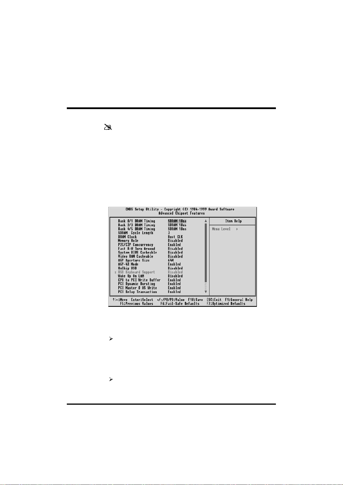
Advanced Chipset Features
This section allows you to configure the system based on the specific
features of the installed chipset. This chipset manages bus speeds and
access to system memory resources, such as DRAM and the external
cache. It also coordinates communications between the conventional
ISA bus and the PCI bus. It must be stated that these items should
never need to be altered.
The default settings have been chosen because they provide the best
operating conditions for your system. The only time you might consider making any changes would be if you discovered that data was
being lost while using your system.
Bank x/x DRAM Timing
This value in this field is set by the system board manufacturer, depending on whether the board has paged DRAMS or EDO DRAMS.
The choice: SDRAM 10ns, SDRAM 8ns, Normal, Medium, Fast,
Turbo.
SDRAM Cycle Length
This field allows you to set the SDRAM latency timer.
The choice: 2, 3.
- 53 -
Page 56

DRAM Clock
This item set the DRAM Read/Write timings that the system uses.
The choice: Host CLK, HCLK-33M, HCLK+33M.
Memory Hole
In order to improve performance, some space in memory can be
reserved for ISA cards.
The choice: Disabled, 15M-16M.
P2C/C2P Concurrency
This item allows you to enabled/disabled the PCI to CPU, CPU to PCI
concorrency.
The choice: Enabled, Disabled.
Fast R-W Turn Around
This item controls the DRAM Timing. It allows you to enabled/Disabled the fast read/write turn around.
The choice: Enabled, Disabled.
System BIOS Cacheable
Selecting Enabled allows caching of the system BIOS ROM at F0000hFFFFFh, resulting in better system performance. However, if any
program writes to this memory area, a system error may result.
The choice: Enabled, Disabled.
Video RAM Cacheable
This is a new cache technology for the video memory of the processor.
It can greatly improve the display speed by caching the display data.
You must leave this on the default setting of Disabled if your display
card cannot support this feature or else your system may not boot.
The choice: Enabled, Disabled.
AGP Aperture Size (MB)
This item allows the user to set memory-mapped, graphics data structures can reside in Graphics Aperture.
The choice: 4M, 8M, 16M, 32M, 64M, 128M.
- 54 -
Page 57

AGP-4X Mode
This item allows you to enable/disable AGP-4X function. See
www.apgforum.org for AGP information.
The choice: Enabled, Disabled.
On Chip USB
Select Enabled if your system contains a Universal Serial Bus (USB)
controller and you have a USB peripheral.
The choice: Enabled, Disabled.
USB Keyboard Support
Select Enabled if your system contains a Universal Serial Bus (USB)
controller and you have a USB keyboard.
The choice: Enabled, Disabled.
Wake Up On LAN
This item determine the system will resume by activity of LAN. If
enabled this feature system will power-on itself from power off when
the activity of LAN.
The choice: Enabled, Disabled.
CPU to PCI Write Buffer
When enabled, up to four Dwords of data can be written to the PCI
bus without interrupting the CPU. When disabled, a write buffer is
not used and the CPU read cycle will not be completed until the PCI
bus signals that it is ready to receive the data.
The choice: Enabled, Disabled.
PCI Dynamic Bursting
When Enabled, data transfers on the PCI bus, where possible, make
use of the high performance PCI burst protocol, in which greater
amounts of data are transferred at a single command.
The choice: Enabled, Disabled.
- 55 -
Page 58

PCI Master 0 WS Write
When Enabled, writes to the PCI bus are command with zero wait
states.
The choice: Enabled, Disabled.
PCI Delay Transaction
The chipset has an embedded 32-bit posted write buffer to support
delay transactions cycles. Select Enabled to support compliance with
PCI specification version 2.1.
The choice: Enabled, Disabled.
PCI #2 Access #1 Retry
This item allows you enable/disable the PCI #2 Access #1 Retry.
The choice: Enabled, Disabled.
AGP Master 1 WS Write
This implements a single delay when writing to the AGP Bus. By
default, two-wait states are used by the system, allowing for greater
stability.
The choice: Enabled, Disabled.
AGP Master 1 WS Read
This implements a single delay when reading to the AGP Bus. By
default, two-wait states are used by the system, allowing for greater
stability.
The choice: Enabled, Disabled.
Memory Parity/ECC Check
This item enabled to detect the memory parity and error checking &
correcting.
The choice: Enabled, Disabled.
- 56 -
Page 59
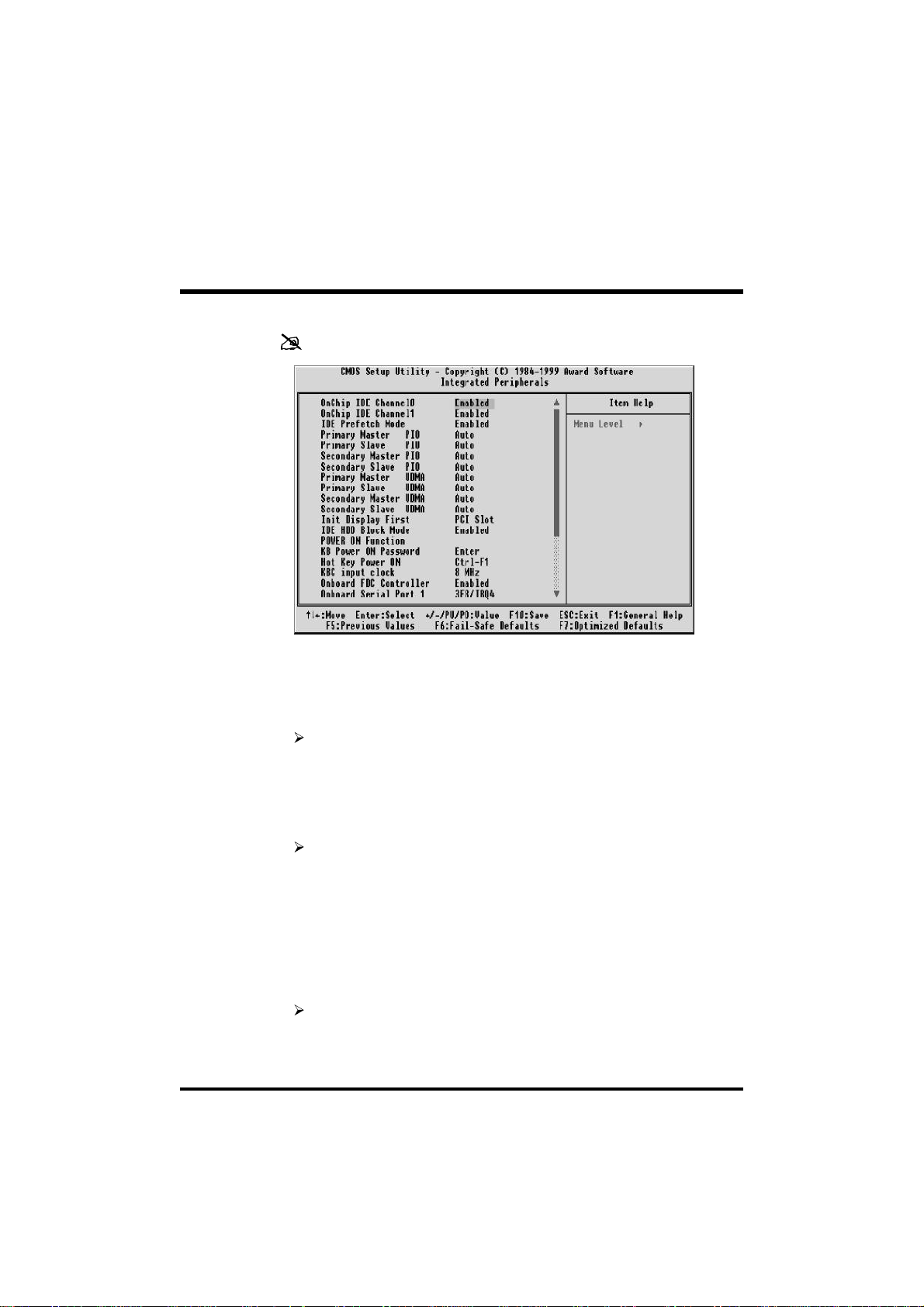
Integrated Peripherals
OnChip IDE Channel0
This item is used to defined on chip Primary PCI IDE controller is
Enable or Disable setting.
The choice: Enabled, Disabled.
OnChip IDE Channel1
This item is used to defined on chip Secondary PCI IDE controller is
Enable or Disable setting.
The choice: Enabled, Disabled.
IDE Prefetch Mode
Enable prefetching for IDE drive interfaces that support its faster drive
accesses. If you are getting disk drive errors, change the setting to
omit the drive interface where the errors occur. Depending on the
configuration of your IDE subsystem, this field may not appear, and it
does not appear when the Internal PCI/IDE field, above is Disabled.
The choice: Enabled, Disabled.
- 57 -
Page 60

Primary Master / Slave PIO
In this items, there are five modes defined in manual mode and one
automatic mode. There are 0, 1, 2, 3, 4, and AUTO is the default
settings for on board Primary Master / Slave PIO timing.
The choice: Auto, Mode 0, Mode 1, Mode 2, Mode 3, Mode 4.
Secondary Master / Slave PIO
In this items, there are five modes defined in manual mode and one
automatic mode. There are 0, 1, 2, 3, 4, and AUTO is the default
settings for on board Secondary Master / Slave PIO timing.
The choice: Auto, Mode 0, Mode 1, Mode 2, Mode 3, Mode 4.
Primary Master / Slave UDMA
On this mainboard, AV11 PCIset improves IDE transfer rate using Bus
Master UltraDMA 33/66 IDE which can handle data transfer up to
33MB/sec. Auto is the default settings for on board Primary Master /
Slave UltraDMA 33/66.
Note : Your hard drive must also support UDMA for this feature to
work.
The choice: Auto, Disabled.
Secondary Master / Slave UDMA
On this mainboard, AV64 PCIset improves IDE transfer rate using Bus
Master UltraDMA 33/66 IDE which can handle data transfer up to
33MB/sec. Auto is the default settings for on board Secondary Master /
Slave UltraDMA 33/66.
Note : Your hard drive must also support UDMA for this feature to
work.
The choice: Auto, Disabled.
Init Display First
This item is used to determine initial device when system power on.
The choice: AGP, PCI Slot.
- 58 -
Page 61

IDE HDD Block Mode
Block mode is also called block transfer, multiple commands, or
multiple sector read/write. If your IDE hard drive supports block mode
(most new drives do), select Enabled for automatic detection of the
optimal number of block read/writes per sector the drive can support.
The choice: Enabled, Disabled.
POWER ON Function
This item is used to defined Keyboard & PS/2 mouse power-on function enabled or disabled.
The choice: Password, Hot KEY, Mouse Left, Mouse Right, Button
Only, keyboard 98.
Note:1. When item of PS/2 Mouse or HOT-Key is selected, please
also adjust jumper JP38 to the proper position.
2. USB keyboard, USB Mouse and Serial Mouse are not
supported to this function.
KB Power On Password
Power-on by soft-on/off.
The choice: Enter.
Hot Key Power ON
Power-on by soft-on/off button and keyboard are available.
The choice: <Ctrl><F1> to <Ctrl><F12>.
KBC Input Clock
This item to set the input clock to onboard keyboard controller.
The choice: 6MHz, 8MHz, 12MHz, 16MHz.
Onboard FDC Controller
This item specifies onboard floppy disk drive controller. This setting
allows you to connect your floppy disk drives to the onboard floppy
connector. Choose the "Disabled" settings if you have a separate
control card.
The choice: Enabled, Disabled.
- 59 -
Page 62

Onboard Serial Port 1
This item is used to define onboard serial port 1.
The choice: 3F8/IRQ4, 2F8/IRQ3, 3E8/IRQ4, 2E8/IRQ3, Auto,
Disabled.
Onboard Serial Port 2
This item is used to define onboard serial port 2.
The choice: 3F8/IRQ4, 2F8/IRQ3, 3E8/IRQ4, 2E8/IRQ3, Auto,
Disabled.
UART Mode Select
The main board support IrDA(HPSIR) and Amplitudes Shift Keyed
IR(ASKIR) infrared through COM 2 port.
Note : FIR is not available currently.
The choice: IrDA, ASKIR, Normal.
UART2 Duplex Mode
This item specifies onboard infrared transfer mode to full-duplex. This
item will not show up when IrDA, ASKIR modes are selected.
The choice: Full, Half.
RxD, TxD Active
This item specifies the Active level for RxD & TxD signal.
The choice: Hi, Hi, Hi, Lo, Lo, Hi, Lo, Lo.
IR Transmittion delay
This item enable/disable the delay of the IR state change from Rx to Tx
mode or Tx to Rx mode.
The choice: Enabled, Disabled.
Onboard Parallel Port
This item specifies onboard parallel port address to 378H, 278H,
3BCH or Disabled.
- 60 -
Page 63

Parallel Port Mode
This item specifies onboard parallel port mode. The options are SPP
(Standard Parallel Port), EPP(Enhanced Parallel Port), ECP (Extended
Capabilities Port), and EPP+ECP.
ECP Mode Use DMA
This item specifies DMA (Direct Memory Access) channel when ECP
device is in use. The options are DMA 1 and DMA 3. This item will
not show up when SPP and EPP printer mode is selected.
The choice: 1, 3
EPP Mode Select
This item select the EPP Mode.
The choice: EPP1.7, EPP1.9.
POWER After PWR-Fail
This item to set the ATX power supply status when power resume after
unexpected power fail. When off is selected, power supply will
maintain on soft-off status, when power is resume. When on is selected, power supply will turn on, and when former-sts is selected,
power supply will maintain on the status before unexpected power
fail.
The choice: On, Former-Sts, Off.
- 61 -
Page 64
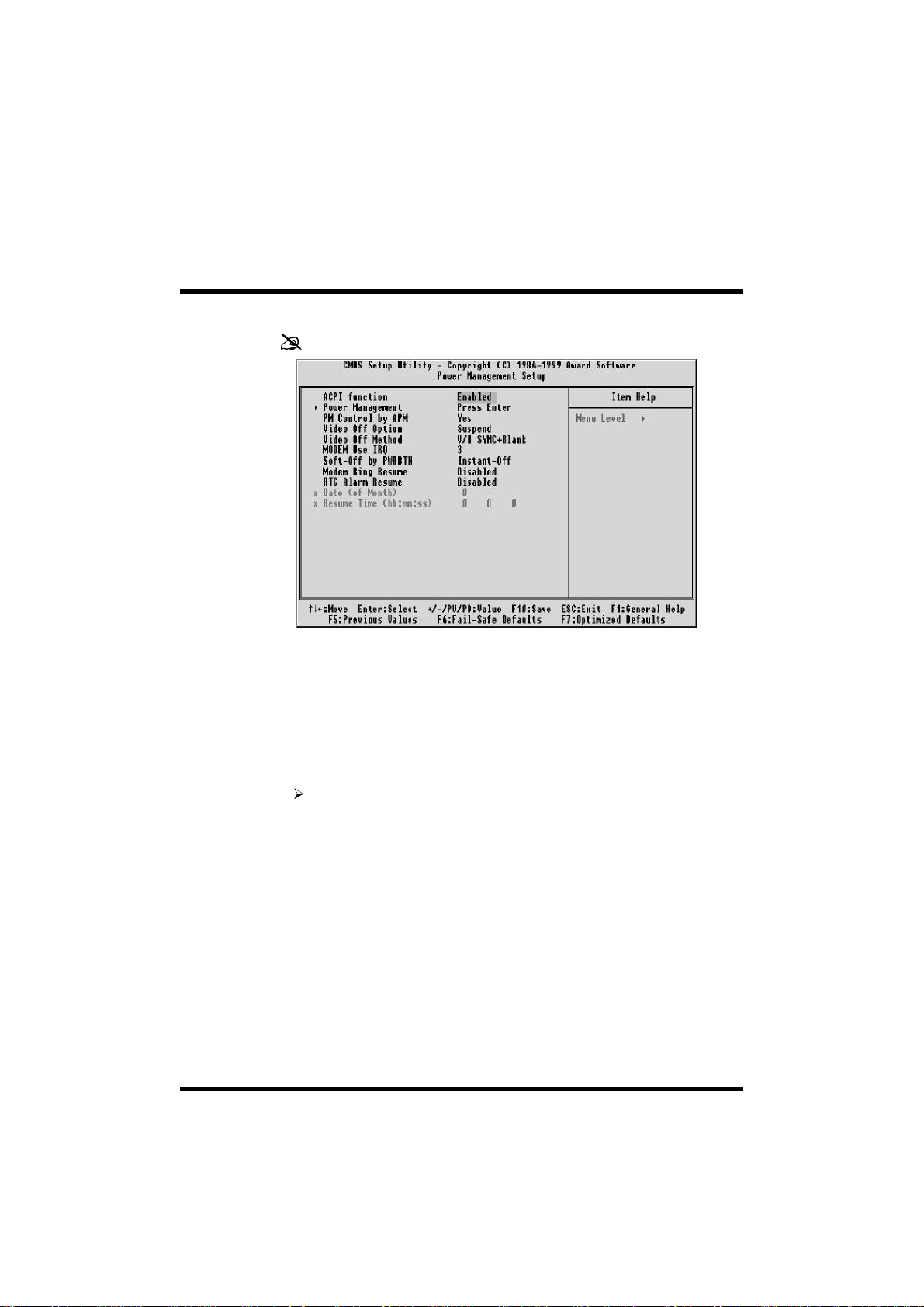
Power Management Setup
The Power Management Setup allows you to configure you system to
most effectively save energy while operating in a manner consistent
with your own style of computer use.
ACPI Function
This item allows you to enable/disable the Advanced Configuration
and Power Management (ACPI).
The choice: Enabled, Disabled.
Power Management
This category allows you to select the type (or degree) of power saving
and is directly related to the following modes: HDD Power Down,
Doze Mode, Suspend Mode
Min. Power Saving Minimum power management. Doze Mode
= 1 hr. Standby Mode = 1 hr., Suspend
Mode = 1hr., and HDD Power Down = 15
min.
Max. Power Saving Maximum power management -- ONLY
AVAILABLE FOR SL CPU's. Doze Mode = 1
min.,
Standby Mode = 1 min., Suspend Mode = 1
min., and HDD Power Down = 1 min.
- 62 -
Page 65

User Defined Allows you to set each mode individually.
When not disabled, each of the ranges are
from 1 min. to 1 hr. except for HDD Power
Down which ranges from 1 min. to 15 min.
and disable.
The choice: Min Saving, Max Saving, User Define.
PM Control by APM
If this item set to No, system BIOS will be ignored and APM calls the
power to manage the system.
If this item setup to Yes, system BIOS will wait for APM's prompt
before it enter any PM mode e.g. DOZE, STANDBY or SUSPEND.
The choice: Yes, No.
Video Off Option
This item define when to activate the video off feature for monitor
power management.
The choice: Suspend, Doze, N/A.
Video Off Method
This determines the manner in which the monitor is blanked.
V/H SYNC+Blank This selection will cause the system to turn off
the vertical and horizontal synchronization
ports and write blanks to the video buffer.
Blank Screen This option only writes blanks to the video
buffer.
DPMS Initial display power management signaling.
The choice: V/H SYNC+Blank, Blank Screen, DPMS Support.
MODEM Use IRQ
This item determines the IRQ in which the MODEM can use.
The choice: 3, 4, 5, 7, 9, 10, 11, N/A.
- 63 -
Page 66

Soft-Off by PWRBTN
The setting of Instant-Off allows the ATX switch to function as a
normal system power off button when pressed for less than 4 seconds.
The setting of Delay 4 Sec. Allows the button to have a dual function
where to press the button for less than 4 seconds will place the system
in suspend mode, and pressing the button for more than 4 seconds
will shut place the system off.
The choice: Instant-Off, Delay 4 Sec.
Modem Ring Resume
When set to Enabled, any event occurring Modem Ring/activity of
LAN will awaken a system which has been powered down.
The choice: Enabled, Disabled.
RTC Alarm Resume
When set to Enabled RTC Alarm Resume, you could set the date (of
month) and timer (hh:mm:ss), any event occurring at RTC will awaken
system which has been powered down.
The choice: Enabled, Disabled.
Date (of Month) Alarm
This item select the alarm date.
Key in a DEC number: Min=0, Max=31.
Time (hh : mm : ss) Alarm
This item select the alarm time.
- 64 -
Page 67
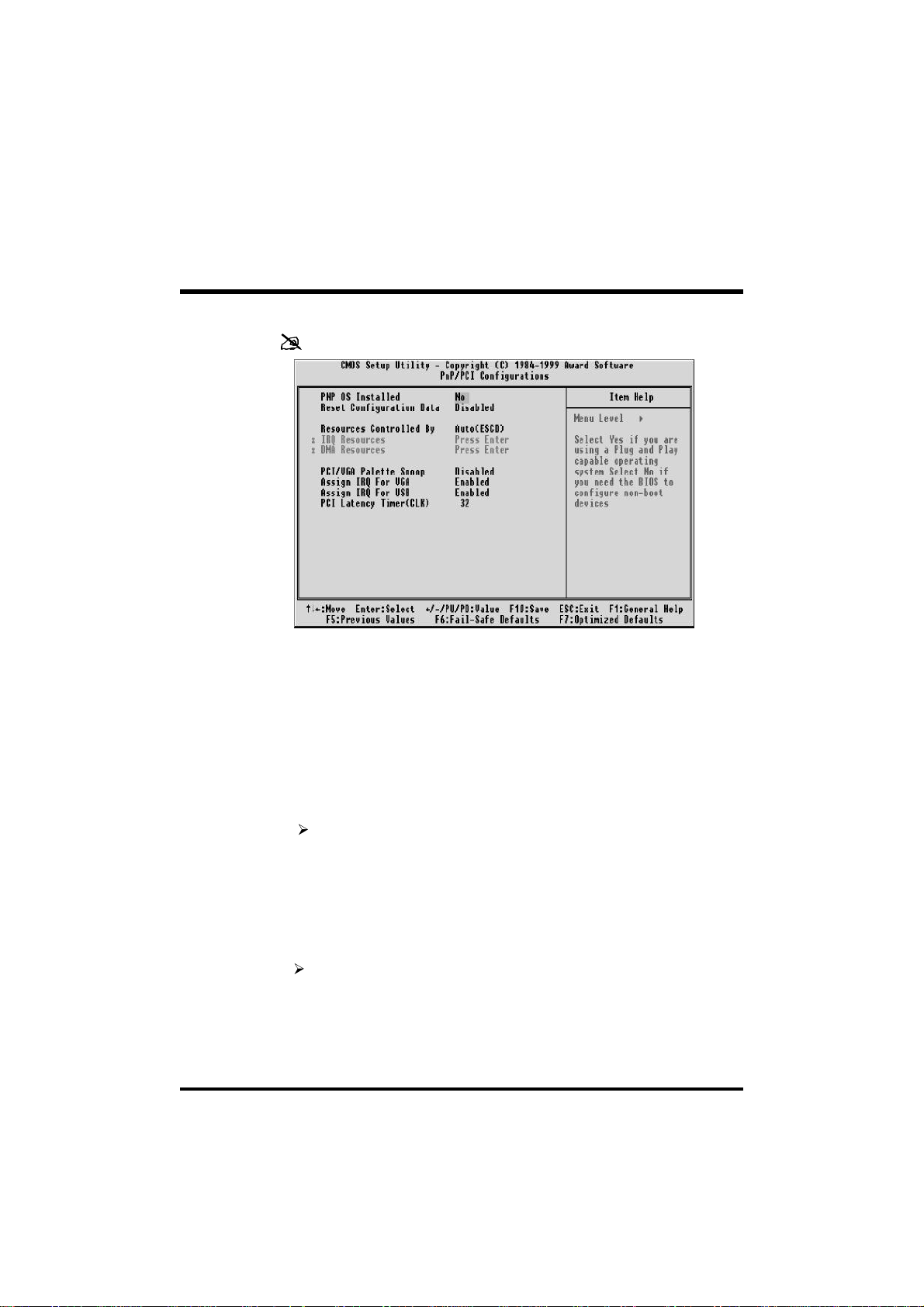
PnP/PCI Configuration
This section describes configuring the PCI bus system. PCI, or Personal Computer Interconnect, is a system which allows I/O devices to
operate at speeds nearing the speed the CPU itself uses when communicating with its own special components. This section covers some
very technical items and it is strongly recommended that only experienced users should make any changes to the default settings.
PNP OS Installed
This item allows you to determine install PnP OS or not.
The choice: Yes, No.
Reset Configuration Data
Normally, you leave this field Disabled. Select Enabled to reset Extended System Configuration Data (ESCD) when you exit Setup if you
have installed a new add-on and the system reconfiguration has
caused such a serious conflict that the operating system can not boot.
The choice: Enabled, Disabled .
Resource controlled by
The Award Plug and Play BIOS has the capacity to automatically
configure all of the boot and Plug and Play compatible devices. However, this capability means absolutely nothing unless you are using a
- 65 -
Page 68

Plug and Play operating system such as Windows 95. If you set this
field to "manual" choose specific resources by going into each of the
sub menu that follows this field (a sub menu is preceded by a ">").
The choice: Auto(ESCD), Manual.
IRQ/DMA Resources
When resources are controlled manually, assign each system interrupt
a type, depending on the type of device using the interrupt.
IRQ3/4/5/7/9/10/11/12/14/15 assigned to
This item allows you to determine the IRQ assigned to the ISA bus and
is not available to any PCI slot. Legacy ISA for devices compliant with
the original PC AT bus specification, PCI/ISA PnP for devices compliant with the Plug and Play standard whether designed for PCI or ISA
bus architecture.
The Choice: Reserved, PCI Device.
DMA 0/1/3/5/6/7 assigned to
These items allow you to determine the DMA assigned to the ISA bus
and is not available for PCI slot.
The choice: Legacy ISA, PCI/ISA PnP.
PCI/VGA Palette Snoop
Leave this field at Disabled.
The Choice: Enabled, Disabled.
Assign IRQ For VGA
This item allows the user to set VGA IRQ Routing table Enabled or
Disabled.
The choice: Enabled, Disabled.
Assign IRQ For USB
This item allows the user the option to assign an IRQ to on-board USB
controller.
Since the on-board controller is always enabled, if no IRQ is assigned
to it, there will be a question mark report on the system device under
Windows 95/98.
The choice: Enabled, Disabled.
- 66 -
Page 69

PCI Latency Timer (CLK)
The number of clocks programed in the PCI Latency Timer represents
the guaranteed time slice allocated to the VT82C694X, after which it
must complete the current data transfer phase and surrender the bus as
soon as its bus grant is removed.
The PCI Latency Timer is used to guarantee to the PCI agents a minimum amount of the sytem resource.
The Choice: 0 ~ 255.
- 67 -
Page 70
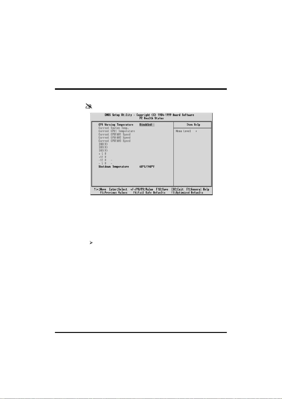
PC Health Status
Note: This screen will be shown up if optional features available.
CPU Warning Temperature
Since the mainboard support CPU temperature monitoring and overhear alert. This item allows the user to set the threshold of CPU
warning temperature. When CPU temperature over the threshold,
system will slow down clock to prevent CPU damage.
The choice: Disabled, 50°C/122°F, 53°C/127°F, 56°C/133°F,
60°C/140°F, 63°C/145°F, 66°C/151°F, 70°C/158°F.
Current System Temp
Since the mainboard support System temperature monitoring and
overheat alert. This item indicate the current main board temperature.
Current CPU1 Temperature
Since the mainboard support CPU temperature monitoring and
overheat alert. This item indicate the current Processor temperature.
Current CPU1/2/3 FAN Speed
The mainboard can detect three fans rotation speed for CPU cooler.
- 68 -
Page 71

IN0(V) ~ IN2(V), +5V ~ -5V
The mainboard support CPU and mainboard voltages monitoring. The
onboard hardware monitor is able to detect the voltages output of the
voltage regulators and power supply.
Shutdown Temperature
Select the combination of lower and upper limits for the system shutdown temperature, if your computer contains an environmental monitoring system. If the temperature extends beyound either limit, the
system shuts down.
The choice: Disabled, 60°C/140°F, 65°C/149°F, 70°C/158°F,
75°C/167°F.
- 69 -
Page 72

Frequency/Voltage Control
Auto Detect DIMM/PCI Clk
This item allows you to enable/disable auto detect DIMM/PCI Clock.
The choice: Enabled, Disabled.
Spread Spectrum
This item allows you to enable/disable the spread spectrum modulate.
The choice: Disabled, 0.25%, 0.5%.
CPU Host Clock (CPU/PCI)
The choice: Default, 66/33MHz ~ 150/37MHz.
CPU/PCI Clock Ratio
This item allows the user to adjust CPU Host Clock/Internal Clock
ration when JP37 is set to Auto.
The user may adjust CPU Clock Ratio from x2 to x8.
This item will not show up when JP37 is set to Manual.
The choice: x2, x2.5, x3, x3.5, x4, x4.5, x5, x5.5, x6, x6.5, x7,
x7.5, x8.
- 70 -
Page 73

Load Fail-Safe Defaults
When you press <Enter> on this item you get a confirmation dialog
box with a message similar to:
Load Fail-Safe Defaults (Y/N) ? N
Pressing 'Y' loads the BIOS default values for the most stable,
minimal-performance system operations.
Load Optimized Defaults
When you press <Enter> on this item you get a confirmation dialog
box with a message similar to:
Load Optimized Defaults (Y/N) ? N
Pressing 'Y' loads the default values that are factory settings for
optimal performance system operations.
- 71 -
Page 74
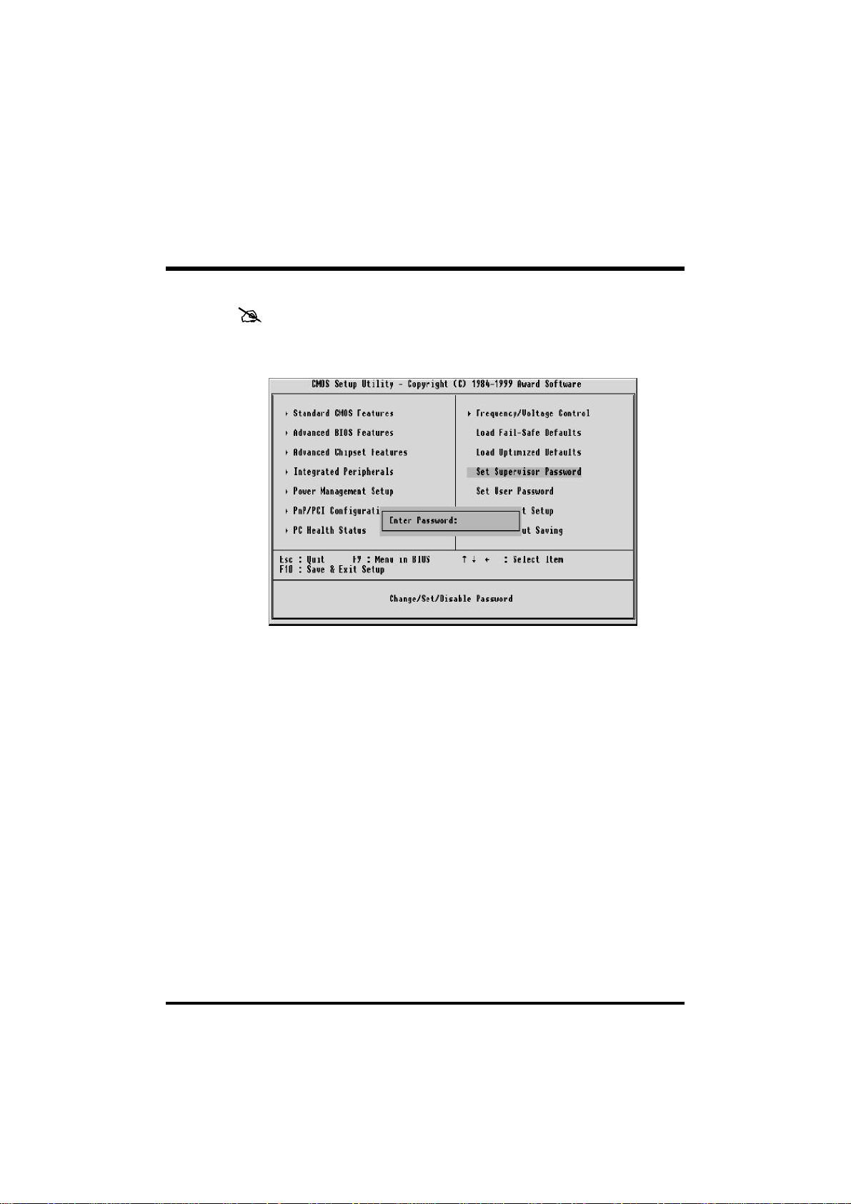
Supervisor/User Password Setting
You can set either supervisor or user password, or both of then. The
differences between are:
Supervisor Password and User Password
The options on the Password screen menu make it possible to restrict
access to the Setup program by enabling you to set passwords for two
different access modes: Supervisor mode and User mode.
In general, Supervisor mode has full access to the Setup options,
whereas User mode has restricted access to the options. By setting
separate Supervisor and User password, a system supervisor can limit
who can change critical Setup values.
Enter Password
Type the password, up to eight characters, and press <Enter>. The
password typed now will clear any previously entered password from
CMOS memory. You will be asked to confirm the password. Type
the password again and press <Enter>. You may also press <Esc>
to abort the selection and not enter a password.
To disable password, just press <Enter> when you are prompted to
enter password. A message will confirm the password being disabled.
Once the password is disabled, the system will boot and you can enter
Setup freely.
- 72 -
Page 75

Password Disable
If you select System at Security Option of BIOS Features Setup Menu,
you will be prompted for the password every time the system is
rebooted or any time you try to enter Setup. If you select Setup at
Security Option of BIOS Features Setup Menu, you will be prompted
only when you try to enter Setup.
Warning : Retain a record of your password in a safe place. If you
forget the password, the only way to access the system is
to clear CMOS, please refer to page 29
"Clear CMOS".
- 73 -
Page 76

Save & Exit Setup
Pressing <Enter> on this item asks for confirmation:
Save to CMOS and EXIT (Y/N)? Y
Pressing "Y" stores the selections made in the menus in CMOS - a
special section of memory that stays on after you turn your system off.
The next time you boot your computer, the BIOS configures your
system according to the Setup selections stored in CMOS. After saving
the values the system is restarted again.
Exit Without Saving
Pressing <Enter> on this item asks for confirmation:
Quit without saving (Y/N)? Y
This allows you to exit Setup without storing in CMOS any change.
The previous selections remain in effect. This exits the Setup utility
and restarts your computer.
- 74 -
 Loading...