

Page 1

AV49/AV49N
Socket 478
Pentium 4/Celeron, 478-pin Processor
with 400/533 MHz FSB
Based MAIN BOARD
User's Manual
Page 2

Shuttle® AV49/AV49N
Pentium 4/Celeron 478-pin Processor with 400/533 MHz FSB
Based MAIN BOARD
Manual Version 1.0
Copyright
Copyright© 2002 by Shuttle® Inc. All Rights Reserved.
No part of this publication may be reproduced, transcribed, stored in a retrieval system,
translated into any language, or transmitted in any form or by any means, electronic,
mechanical, magnetic, optical, chemical, photocopying, manual, or otherwise, without
prior written permission from Shuttle® Inc.
Disclaimer
Shuttle® Inc. shall not be liable for any incidental or consequential damages resulting from the
performance or use of this product.
This company makes no representations or warranties regarding the contents of this manual.
Information in this manual has been carefully checked for reliability; however, no guarantee is
given as to the correctness of the contents. In the interest of continued product improvement,
this company reserves the right to revise the manual or include changes in the specifications
of the product described within it at any time without notice and without obligation to notify any
person of such revision or changes. The information contained in this manual is provided for
general use by the customers.
Trademarks
Shuttle is a registered trademark of Shuttle Inc.
Intel, Pentium is a registered trademarks of Intel Corporation.
VIA is a registered trademark of VIA Corporation.
PS/2 is a registered trademark of IBM Corporation.
AWARD is a registered trademark of Award Software Inc.
Microsoft and Windows are registered trademarks of Microsoft Corporation.
General Notice: Other brand and product names used herein are for identification purposes
only and may be trademarks of their respective owners.
M614
Page 3

TABLE OF CONTENTS
WHAT'S IN THE MANUAL .....................................................................5
Quick Reference................................................................................................5
About This Manual ............................................................................................5
1 INTRODUCTION .................................................................................6
1.1 TO DIFFERENT USERS ..............................................................................6
FIRST-TIME DIY SYSTEM BUILDER ............................................................6
EXPERIENCED DIY USER .........................................................................6
SYSTEM INTEGRA TOR ...............................................................................6
1.2 ITEM CHECKLIST: ......................................................................................7
2 FEATURES..........................................................................................8
2.1 SPECIFICATIONS ........................................................................................8
3 HARDWARE INSTALLATION ...........................................................11
3.1 STEP BY STEP INSTALLATION................................................................ 11
Accessories of AV49/AV49N................................................................. 11
STEP 1 Install the CPU...........................................................................12
STEP 2 Set Jumpers..............................................................................14
STEP 3 Install DDR SDRAM System Memory ........................................14
STEP 4 Install Peripherals in System Case.............................................15
STEP 5 Mount the Mainboard on the Computer Chassis ........................16
STEP 6 Connect Front Panel Switches/LEDs/Speaker/USB ..................17
STEP 7 Connect IDE and Floppy Disk Drives.........................................19
STEP 8 Connect Other Internal Peripherals ............................................20
STEP 9 Connect the Power Supply ........................................................21
STEP 10 Install Add-on Cards in Expansion Slots ..................................22
STEP 1 1 Connect External Peripherals to Back-Panel............................23
STEP 12 First T ime System Boot Up......................................................24
- 1 -
Page 4

STEP 13 Install Drivers & Software Components....................................25
3.2 JUMPER SETTINGS ..................................................................................26
JUMPERS & CONNECTORS GUIDE ....................................................27
Jumpers
Clear CMOS Setting (JP1) ....................................................................30
FSB Speed Configuration Setting (JP2) ................................................30
USB Power on Setting (JP3/JP4) ...........................................................31
BIOS Flash Protect Setting (JP5)............................................................31
Back-Panel Connectors
PS/2 Keyboard & PS/2 Mouse Connectors ............................................32
Parallel Port Connector...........................................................................32
COM1/2 Port Connectors .......................................................................32
Line-Out (Front-Out) Port Connector .......................................................32
Line-In (Rear-Out) Port Connector...........................................................33
Mic-In Port Connector .............................................................................33
MIDI/GAME Port Connector....................................................................33
USB1/USB2 Port Connectors.................................................................33
LAN Port Connectors(A V49N Only) ........................................................33
Front-Panel Connectors
HDD LED Connector (H LED) ................................................................34
Green LED/Power LED Connector (G LED/PLED) ................................34
Hardware Reset Connector (Reset) ........................................................35
A TX Power On/Of f Switch Connector (PWON)........................................35
EPMI Connectore(EPMI) ........................................................................36
Power LED Connectore(PLED)..............................................................36
Speaker Connector (Speaker)................................................................37
Extended USB Header (USB2/3)............................................................37
- 2 -
Page 5

Internal Peripherals Connectors
Enhanced IDE and Floppy Connector ........................................................... 38
Other Connectors
ATX Power Supply Connector (ATX1/ATX2)................................................ 39
Cooling Fan Connectors for CPU, Chipset, Chassis (FAN1/2/3) ..............40
Wake-on Lan Connector (WOL)..................................................................... 40
Front -Panel Audio Header(J5) ....................................................................... 41
Audio CD-IN Connectors (J7/J8) (White/Black)........................................... 41
Audio Auxiliary-IN Connector (J9) (White) .................................................... 42
SPDIF (J4)........................................................................................................ 42
Audio Center/Bass_Out Header (J6)............................................................43
IR Header (J3).................................................................................................. 43
3.3 SYSTEM MEMORY CONFIGURATION ............................................................ 44
1. INSTALL MEMORY ..................................................................................... 44
2. UPGRADE MEMORY................................................................................. 44
4 SOFTWARE UTILITY .......................................................................... 45
4.1 Mainboard CD Overview .................................................................................. 45
4.2 Install Mainboard Software .............................................................................. 46
4.2. A Install VIA Driver ........................................................................................47
4.2.B Install Audio Device Driver .......................................................................48
4.2.C Install USB 2.0 Driver................................................................................ 49
4.2.D Install LAN Dr iver(AV49N Only) ............................................................... 50
4.3 View the User's Manual .................................................................................... 51
5 BIOS SETUP ........................................................................................ 52
5.1 ENTER BIOS ......................................................................................................... 52
5.2 THE MAIN MENU ................................................................................................. 53
STANDARD CMOS FEATURES.......................................................................55
- 3 -
Page 6

ADVANCED BIOS FEATURES..................................................................59
ADVANCED CHIPSET FEATURES...........................................................62
INTEGRA TED PERIPHERALS...................................................................67
POWER MANAGEMENT SETUP ..............................................................71
PNP/PCI CONFIGURA TION .......................................................................76
PC HEALTH STATUS .................................................................................78
FREQUENCY/VOL T AGE CONTROL..........................................................79
LOAD FAIL-SAFE DEFAULTS ...................................................................80
LOAD OPTIMIZED DEF AU L TS ..................................................................80
SET SUPERVISOR PASSWORD ..............................................................81
SET USER PASSWORD ...........................................................................81
SAVE & EXIT SETUP.................................................................................83
EXIT WITHOUT SA VING.............................................................................83
- 4 -
Page 7

WHAT'S IN THE MANUAL
Quick Reference
Hardware Installation >> Step-by-Step ......................................................Page 11
Jumper Settings >> A Closer Look ............................................................ Page 26
Drivers/Software Utilities >> How to Install .............................................. Page 45
BIOS Setup >> How to Configure ............................................................... Page 52
About This Manual
For First-Time DIY System Builder ................................................................Page 6
For Experienced DIY User ...............................................................................Page 6
For System Integrator .......................................................................................Page 6
- 5 -
Page 8

1 INTRODUCTION
1.1 T o Different Users
First-Time DIY System Builder
Welcome to the DIY world! Building your own computer system is not as
difficult as you may think. To make your first computer DIY experience
successful, right from the start, we have designed the
tion tion
tion section in a step-by-step fashion for all the first-time DIY system builders.
tion tion
Prior to installation, we also suggest you to read the whole manual carefully to
gain a complete understanding of your new Shuttle AV49/N mainboard.
Experienced DIY User
Congratulate on your purchase of the Shuttle AV49/N mainboard. You will
find that installing your new Shuttle AV49/AV49N mainboard is just easy.
Bundled with an array of onboard functions, the highly-integrated AV49/AV49N
mainboard provides you with a total solution to build the most stable and reliable system. Refer to sections
Software UtilitiesSoftware Utilities
Software Utilities to find out how to get the best out of your new mainboard.
Software UtilitiesSoftware Utilities
Chapter 5 BIOSChapter 5 BIOS
Chapter 5 BIOS
Chapter 5 BIOSChapter 5 BIOS
up your system to achieve higher performance.
SetupSetup
Setup also contains the relevant information on how to tune
SetupSetup
3.1 Hardware Installa-3.1 Hardware Installa-
3.1 Hardware Installa-
3.1 Hardware Installa-3.1 Hardware Installa-
3.2 Jumper Settings3.2 Jumper Settings
3.2 Jumper Settings and
3.2 Jumper Settings3.2 Jumper Settings
Chapter 4 Drivers/Chapter 4 Drivers/
Chapter 4 Drivers/
Chapter 4 Drivers/Chapter 4 Drivers/
System Integrator
You have wisely chosen Shuttle AV49/AV49N to construct your system. Shuttle
AV49/N incorporates all the state-of-the-art technology of the P4X400 chipset
from VIA. It integrates the most advanced functions you can find to date in a
compact ATX board.
- 6 -
Page 9
1.2 Item Checklist
U
K
N
2
0
L
-
0
2
2
0
1
2
7
9
5
0
2
0
2
C
F
IT
8712F-A
9944-DX
S
MA
4500
0216CD TA
23A100940
VT8235
2IA2003622
0217CD TAIWA
P4X3
UKN20L-022
0127
950202C F
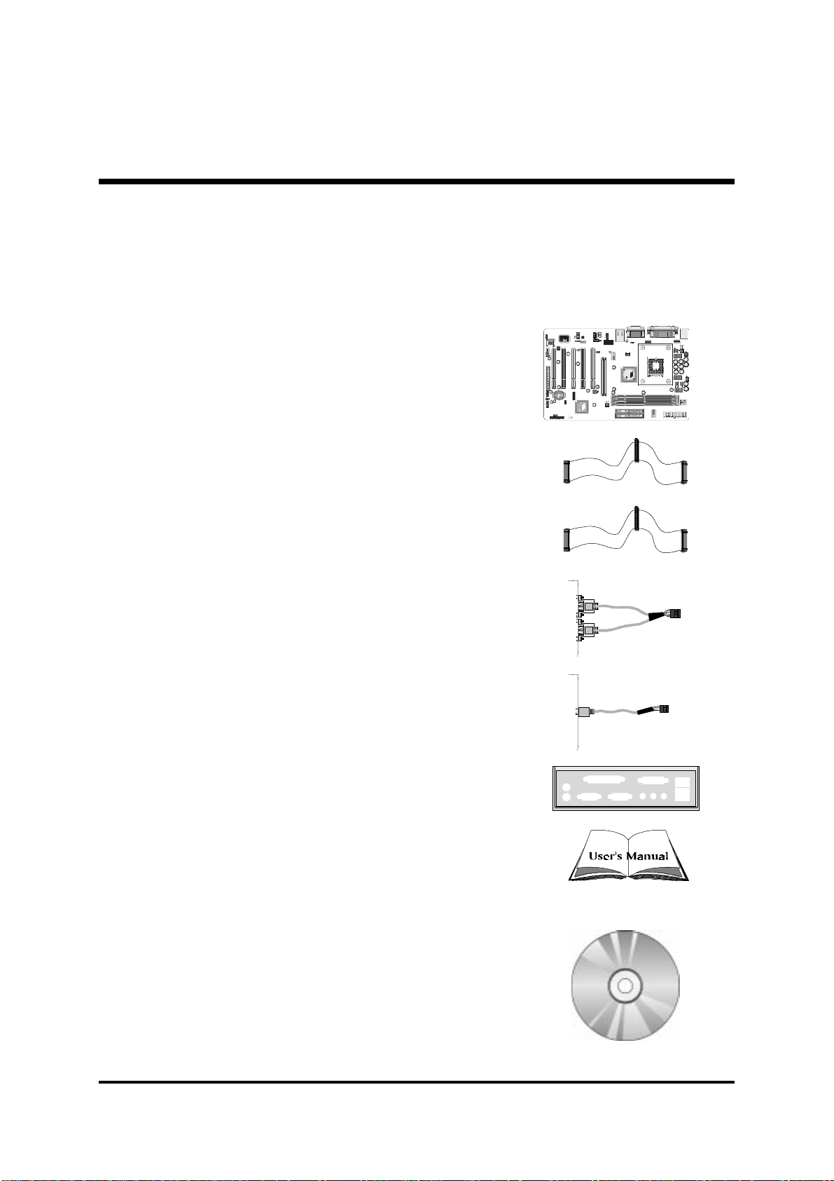
Check all items with you AV49/AV49N mainboard to make sure nothing is
missing. The complete package should include:
One piece of Shuttle AV49/AV49N Mainboard
One piece of ATA
133/100133/100
133/100 Ribbon Cable
133/100133/100
One piece of Floppy Ribbon Cable
One piece of twin ports USB Cable
(optional)(optional)
(optional)
(optional)(optional)
One piece of Audio Cable (Center/Bass Channel)
I/O Shielding
AV49/AV49N User's Manual
One piece of Bundled CD-ROM with containing:
Ø AV49/N user's manual saved in PDF format
Ø VIA 4-IN-1 driver
Ø AC97 Audio driver
Ø VIA LAN driver
Ø USB 2.0 driver
Ø Award Flashing Utility
- 7 -
Page 10

2 FEATURES
AV49/AV49N mainboard is carefully designed for the demanding PC user who wants
high performance and maximum intelligent features in a compact package.
2.1 Specifications
-
CPU Support
Intel Pentium 4/Celeron , 478-pin processors with 400/533 MHz FSB.
-
Chipset
Features VIA P4X400 N.B. and VIA VT8235 S.B..
-
On Board Audio Controller
Compliant with AC'97 2.2 specifications.
6 channel slot selectable OAC Output for multi-channel applications.
-
Versatile Memory Support
Three
PC2700 compliant
-
PCI Expansion Slots
Provides five 32-bit PCI slots.
-
AGP Expansion Slots
Provides one 32-bit AGP slot which supports up to 1X/2X/4X/8X AGP
devices.
-
6 USB Interface Onboard
Ø 2× USB connectors on back-panel and two sets of dual USB ports header
-
I/O Interface
Provides a variety of I/O interfaces:
Ø 1× Floppy interface for 3.5-inch FDD with 720KB, 1.44MB, or 2.88MB
Ø 1× PS/2 mouse connector.
184- pin DIM M
on mid-board.
format or for 5.25-inch FDD with 360K or 1.2MB format.
slots to support up to 3GB of PC1600 , PC2100 or
DD R
SDRAM module.
Ø 1× PS/2 Keyboard connector.
Ø 2× DB9 Serial connectors 16550 UART compatible.
- 8 -
Page 11

Ø 1× Infrared communication port.
(Serial port COM2 can also be redirected to an external IrDA Adapter
for wireless connection.)
Ø 1× DB25 Parallel port supports Standard Parallel Port and Bi-directional
(SPP), Enhanced Parallel Port (EPP), and Extended Capabilities Port (ECP)
data transmission schemes.
Ø 1× Line-Out (Front-Out) port.
Ø 1× Line-In port, shared with Surround-out when multi-channel audio is
enabled.
Ø 1× Mic-In port.
Ø 1× MIDI/GAME port.
Ø 1× RJ45 LAN connector.
PCI Bus Master IDE Controller Onboard
Two Ultra DMA
to a maximum of four IDE devices (one Master and one Slave per channel).
The IDE Bus implements data transfer speeds of up to
also supports Enhanced PIO Modes.
80-pin Cable Backward Compatible Legacy ATAPI Devices, ATAPI IDE CDROM, CD-R, CD-RW, and LS-120 Supports.
ATX Power Supply Connector
ATX power supply unit can connected to the onboard 20-pin Pentium 4
standard ATX power connectors, supporting Suspend and Soft-On/Off by
dual-function power button.
The Pentium 4 ATX power include other 4-pin +12V ATX power
connectors.
Advanced Configuration and Power Interface
Features four power saving modes: S1 (Snoop), S3 (Suspend to RAM), S4
(Suspend to DISK), and S5 (Soft-Off). ACPI provides more efficient Energy
Saving Features controlled by your operating system that supports OS Direct
Power Management (OSPM) functionality.
133/100133/100
133/100 Bus Master Dual-channel IDE ports provide support
133/100133/100
133/100133/100
133/100 MB/sec and
133/100133/100
System BIOS
Provides licensed Award BIOS V6.0 PG on 2Mb Flash EEPROM and supports Green PC, Desktop Management Interface (DMI).
- 9 -
Page 12

ATX Form Factor
System board conforms to ATX specification.
Board dimension: 350mm*190mm.
Advanced Features
Low EMI -Low EMI -
Ø
Low EMI - Built in spread spectrum and automatic clock shut-off of
Low EMI -Low EMI unused PCI/SDRAMS slots to reduce EMI.
Dual Function Power Button - Dual Function Power Button -
Ø
Dual Function Power Button - The system can be in one of two states,
Dual Function Power Button - Dual Function Power Button one is Suspend mode and the other is Soft-Off mode. Pushing the power
button for less than 4 seconds places the system into Suspend mode.
When the power button is pressed for longer than 4 seconds, the system
enters Soft-Off mode.
CPU Clock SettingCPU Clock Setting
Ø
CPU Clock Setting - This item allows users to adjust CPU Host Clock in
CPU Clock SettingCPU Clock Setting
BIOS.
CPU Multiplier SettingCPU Multiplier Setting
Ø
CPU Multiplier Setting - This item allows users to adjust CPU Multiplier
CPU Multiplier SettingCPU Multiplier Setting
in BIOS.
Intelligent Features
Voltage Monitoring -Voltage Monitoring -
Ø
Voltage Monitoring - Monitors various voltages of key elements, such as
Voltage Monitoring -Voltage Monitoring the CPU, and other critical system voltage levels to ensure stable current
passing through mainboard components.
Fan Status MonitoringFan Status Monitoring
Ø
Fan Status Monitoring
Fan Status MonitoringFan Status Monitoring
is monitored for RPM and failure. (CPU Cooling FAN with RPM sensor is
required.)
Temperature Monitoring -Temperature Monitoring -
Ø
Temperature Monitoring - This item allows users to make sure whether
Temperature Monitoring -Temperature Monitoring the CPU or system runs in a suitable temperature.
--
- To prevent CPU from overheating, the CPU fan
--
- 10 -
Page 13

3 HARDW ARE INSTALLATION
Before removing or installing any of these devices including CPU, DIMMs,Before removing or installing any of these devices including CPU, DIMMs,
Before removing or installing any of these devices including CPU, DIMMs,
Before removing or installing any of these devices including CPU, DIMMs,Before removing or installing any of these devices including CPU, DIMMs,
Add-On Cards, Cables, please make sure to unplug the onboard powerAdd-On Cards, Cables, please make sure to unplug the onboard power
Add-On Cards, Cables, please make sure to unplug the onboard power
Add-On Cards, Cables, please make sure to unplug the onboard powerAdd-On Cards, Cables, please make sure to unplug the onboard power
connector.connector.
connector.
connector.connector.
This section outlines how to install and configure your mainboard. Refer to the following
mainboard layout to help you to identify various jumpers, connectors, slots, and ports.
Then follow these steps designed to guide you through a quick and correct installation of
your system.
3.1 Step-by-Step Installation
Accessories Of AV49/AV49N
FAN1
PS/2 Keyboard and
PS/2 Mouse Connectors
Serial Port
Connector (COM1)
Parallel Connector
Serial Port
Connector (COM2)
Line-Out/Line-In/Mic-In
/Game/MIDI Connectors
USB Power on
Setting - JP3
USB & LAN Co nnectors
FAN2
Front Audio
Connector - J5
One AGP 8x Slot
Onboard Audio
Connectors - J7/J8/J9
FSB Speed configuration
Setting - JP2
SPDIF - J4
Center/Bass - J6
I/O Controller
IR Connector - J3
Five PCI Slots
Programmable
Flash EEPROM
BIOS Write
Protection setting - JP5
SOCKET 478 ATX 12V Power
UKN20L-022
0127
950202CF
I
9
M
T
9
A
8
4
7
4
4
1
5
-
2
D
0
F
0
X
-
A
S
VIA P4X400 Chipset
P 4 X 4 0 0
0217CD TAIWAN
2IA2003622
0216CD TAIWAN
23A1009406
Extend USB 2.0 Headers - USB2/3
FAN3
Floppy Connector - FDD1
USB Power on Setting - JP4
Clear CMOS - JP1
Connector - ATX2
9
5
0
2
0
2
C
F
0
1
2
7
U
K
N
2
0
L
-
0
2
2
VT8235
attery
B
ts
Slo
M
IM
e D
re
h
T
set
ip
h
C
5
3
2
8
T
V
IA
V
L)
O
(W
N
A
n L
ake-O
W
1
X
T
r - A
ecto
n
n
o
er C
w
o
P
X
T
A
rs
ecto
n
n
o
E C
o ID
w
T
r - J1
cto
e
n
n
o
el C
an
t-P
n
Fro
- 11 -
Page 14

Step 1.
CPU Installation:
This mainboard supports Intel Pentium 4/Celeron Socket 478 series CPU.
Please follow the step as below to finish CPU installation.
Be careful of CPU orientation when you plug it into CPU socket.
1. Pull up the CPU socket lever and up to 90-degree angle.
CPU socket lever up to
90 degree
2. Locate Pin 1 in the socket and look for a black dot or cut edge on the CPU
upper interface. Match Pin 1 and cut edge, then insert the CPU into the
socket.
CPU pin 1 and cut edge
- 12 -
Page 15

3. Press down the CPU socket lever and finish CPU installation.
Note: Note:
Note: If you do not match the CPU socket Pin 1 and CPU cut edge
Note: Note:
well, it may damage the CPU.
4. The Intel Pentium 4/Celeron processor requires a set of heatsink/fan to ensure
proper cooling of the processor. If heatsink/fan have not been already
bundled with your CPU, you must purchase the heatsink/fan separately and
have it installed. Plug the cable through the heatsink/fan in the CPU fan
power connector located nearby. Note that there are several types of CPU
fan connectors. Normally, if your mainboard supports the hard ware monitoring function, a 3-pin fan power connector should allow your system to
detect the CPU fan's speed. The CPU fan can also run with a 2-pin fan power
connector, however, detection of CPU fan's speed is not supported. Another
type of CPU fan may feature a large 4-pin fan power connector, which does
not support CPU fan's speed detection and must be directly connected to the
system's power supply unit.
- 13 -
Page 16

Step 2.
Set Jumpers
This mainboard is jumperless! The default jumper settings have been set for
the common usage standard of this mainboard. Therefore, you do not need
to reset the jumpers unless you require special adjustments as any of the
following cases:
1. Clear CMOS
2. BIOS Boot block protection
3. Set CPU FSB Frequency
4. Set USB Power On
For first-time DIY system builders, we recommend that you do not change the
default jumper settings if you are not totally familiar with the mainboard
configuration procedures. The factory-set default settings are tuned for optimum system performance. For the advanced users who wish to customize
their system, section
on how to configure your mainboard manually.
3.2 Jumper Settings3.2 Jumper Settings
3.2 Jumper Settings will provide detailed information
3.2 Jumper Settings3.2 Jumper Settings
Step 3.
Install DDR SDRAM System Memory
To install memory, insert DDR SDRAM memory module(s) in any one or two
or three DIMM banks. Note that DDR SDRAM modules are directional and
will not go in the DIMM banks if they are not properly oriented. After the
module is fully inserted into the DIMM bank, lift the clips of both sides of the
DIMM bank to lock the module in place.
DDR SDRAM
- 14 -
Page 17

Step 4.
Install Internal Peripherals in System Case
Before you install and connect the mainboard into your system case, we
recommend that you first assemble all the internal peripheral devices into the
computer housing, including but not limited to the hard disk drive (IDE/
HDD), floppy disk drive (FDD), CD-ROM drive, and ATX power supply unit.
This will greatly facilitate in making the connections to the mainboard described below.
To install IDE & FDD drives, follow this procedure:
1. Set the required jumpers on each device according to the instructions
provided by the manufacturer. (IDE devices, HDD, and CD-ROM, have to
set jumpers to Master or Slave mode depending on whether you install
more than one device of each kind.)
2. Connect IDE cable and FDD cable on the back-panel of the internal peripheral devices to the corresponding headers on board. Note that the
cable should be oriented with its colored stripe (usually red or magenta)
connected to pin#1 both on the mainboard IDE or FDD connector and on
the device as well.
3. Connect an available power cable from your system power supply unit to
the back-panel of each peripheral device. Note that the power cable is
directional and cannot fit in if not properly positioned.
- 15 -
Page 18

Step 5.
Mount the Mainboard on the Computer Chassis
1. You may find that there are a lot of different mounting hole positions both on
your computer chassis and on the mainboard. To choose correct mounting
holes, the key point is to keep the back-panel of the mainboard in a close fit
with your system case, as shown below.
2. After deciding on the proper mounting holes, position the studs between the
frame of the chassis and the mainboard. The studs are used to fix the
mainboard and to keep a certain distance between the system chassis and
the mainboard, in order to avoid any electrical shorts between the board and
the metal frame of the chassis. (If your computer case is already equipped
with mounting studs, you will need to tighten screws to attach the
mainboard.)
Note: Note:
Note: In most computer housings, you will be able to find 4 or more attach-
Note: Note:
ment points to install mounting studs and then fix the mainboard. If
there aren't enough matching holes, then make sure to install at least 4
mounting studs to ensure proper attachment of the mainboard.
- 16 -
Page 19
Step 6.
GLED/PLED
HLED
EPMI
Reset
Speaker
PWON
PLED
GLED/PLED
HLED
EPMI
Reset
Speaker
PWON
PLED
GLED/PLED
HLED
EPMI
Reset
Speaker
PWON
PLED
Connect Front Panel Switches/LEDs/Speaker/USB
You can find there are several different cables already existing in the system
case and originating from the computer's front-panel devices (HDD LED,
Power LED, Reset Switch, PC Speaker, or USB devices etc.) These cables
serve to connect the front-panel switches, LEDs, and USB connectors to the
mainboard's front-panel connectors group (J1 and USB2/3), as shown below.
USB2
1
USB 3 & 4
USB3
1
USB 5 & 6
1. HDD-LED (HLED)
J1
2. Green LED/Power LED (GLED/PLED)
1
D
LE
H
eset
R
I
M
P
E
peaker
S
-
+
-
+-
+
D
LE
-
/P
D
+
LE
G
N
O
W
P
+
D
LE
P
-
J1
1
J1
3. Hardware Reset Switch Button (Reset)
J1
- 17 -
-
+
1
-
+-
+-
+
+
-
1
+
-
Page 20

4. ATX Soft Power On/Off (PWON)
USB port 5
USB port 4
USB port 6
GLED/PLED
HLED
EPMI
Reset
Speaker
PWON
PLED
GLED/PLED
HLED
EPMI
Reset
Speaker
PWON
PLED
GLED/PLED
HLED
EPMI
Reset
Speaker
PWON
PLED
GLED/PLED
HLED
EPMI
Reset
Speaker
PWON
PLED
-
+
1
J1
5. System Management Interface Button(EPMI)
J1
6. Power LED (PLED)
J1
7. PC Speaker (Speaker)
J1
-
+-
+-
+-
+-
+
-
+
1
-
+
+
-
1
+
-
-
+
1
-
+
8. Extended USB Header(USB2/USB3)
- 18 -
D
D
A
A
+
T
T
A
5
A
V
+
-
+
D
D
5
A
A
V
T
T
A
A
+
-
USB port 3
D
D
A
G
G
N
N
D
C
G
K
N
E
D
Y
A
T
+
T
N
N
A
5
A
V
11
+
5
V
D
C
+
-
G
D
D
A
T
A
-
K
N
A
E
T
D
Y
A
+
Page 21
Step 7.
Connect IDE and Floppy Disk Drives
1. IDE cable connector
2. Floppy cable connector
FDD1
IDE 1
1
1
IDE 2
1
- 19 -
Page 22
Step 8.
Connect Other Internal Peripherals
1. Auxiliary-IN, CD-IN, Bass/Center-Out connectors
2. IR header
J7
J8
CD_INP
CD_IN
AUX_IN
Bass/
Center-Out
1
J6
J9
IR
- 20 -
1
JP3
Page 23

3. Wake On LAN headers
Step 9.
Connect the Power Supply
WOL
1
1. System power connector
ATX 2
ATX 1
- 21 -
Page 24
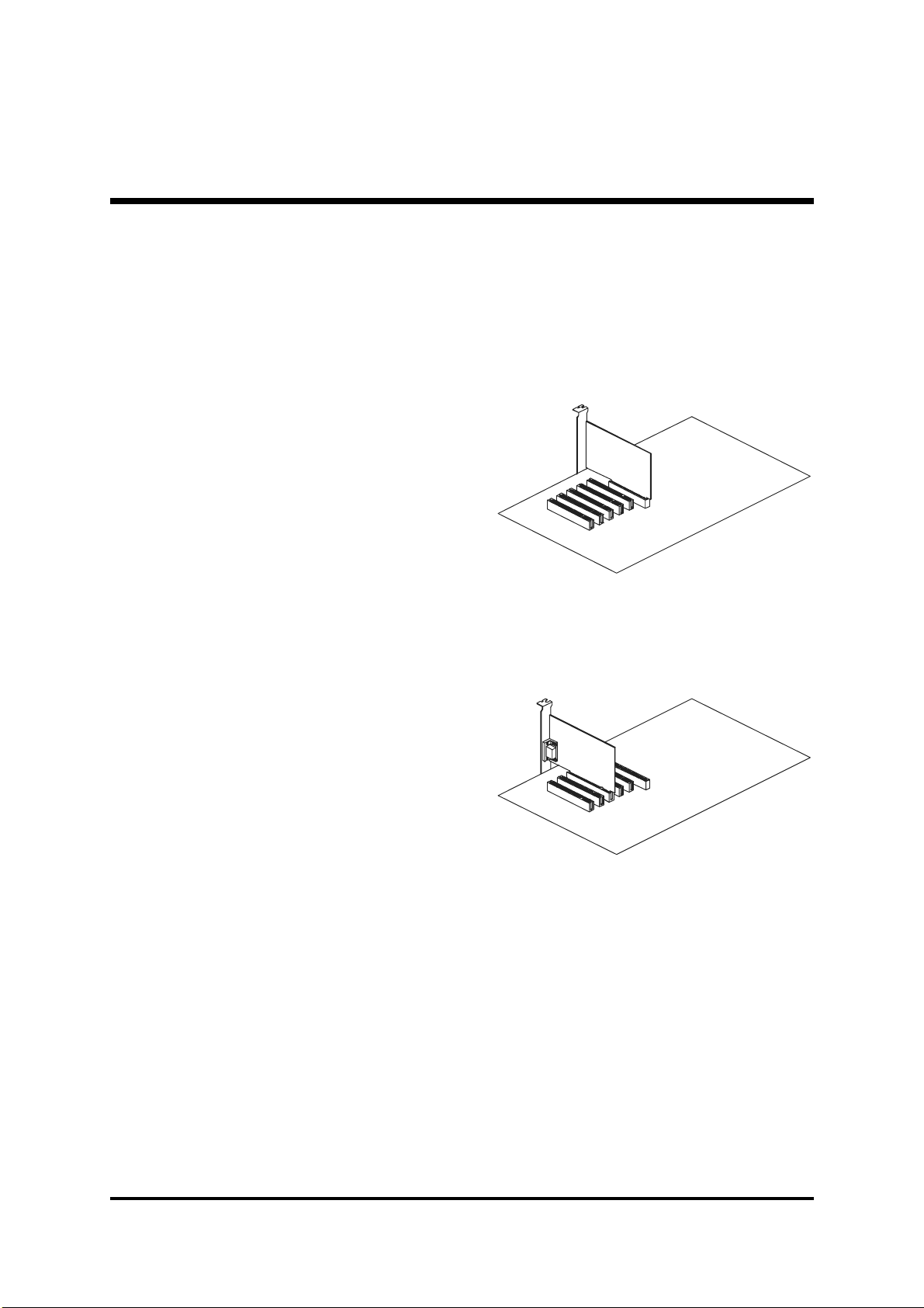
Step 10.
Install Add-on Cards in Expansion Slots
1. Accelerated Graphics Port (AGP) Card
2. PCI Card
- 22 -
Page 25
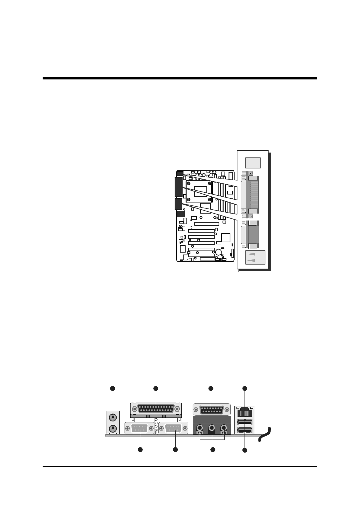
Step 11
Connect External Peripherals to Back-Panel
You are now ready to put the computer case back together and get on to the
external peripherals connections to your system back-panel.
VGA PRT
1. PS/2 Mouse and PS/2 Keyboard
2. COM1 Port
3. COM2 Port
4. Parallel Port
5. Audio Line-Out /Line-In / Mic-In Ports
6. MIDI/GAME Port
7. LAN Port
8. USB port 1/USB port 2
4
foxconn
2315
6
7
8
- 23 -
Page 26

Step 12
First Time System Boot Up
To assure the completeness and correctness of your system installation, you
may check the above installation steps once again before you boot up your
system for the first time.
1. Insert a bootable system floppy disk (DOS 6.2x, Windows 95/98/NT, or
others) which contains FDISK and FORMAT utilities into the FDD.
2. Turn on the system power.
3. First, you must use the FDISK utility to create a primary partition of the
hard disk. You can also add an extended partition if your primary partition does not use all of the available hard disk space. If you choose to add
an extended partition, you will have to create one or more logical partitions to occupy all the space available to the extended partition. The
FDISK utility will assign a drive letter (i.e., C:, D:, E:,...) to each partition
which will be shown in the FDISK program. After FDISK procedure,
reboot your system by using the same system floppy disk.
Note:Note:
Note: DOS 6.2x and Windows 95A can only support up to 2.1GB of
Note:Note:
HDD partition. If you use the FDISK utility with one of the operating systems mentioned above, you can only install your HDD into
partitions no larger than 2.1GB each.
4. Now, use the FORMAT utility to format all the partitions youve created.
When formatting the primary partition (C:), make sure to use the FORM-
AT C: /S command.
Note:Note:
Note: FORMAT C: /S can transfer all the necessary system files into the
Note:Note:
primary partition of your hard disk. Then, your HDD will become a
bootable drive.
5. Install all the necessary drivers for CD-ROM, Mouse, etc.
6. Setup the complete operating system according to your OS installation
guide.
- 24 -
Page 27

Step 13.
Install Drivers & Software Components
Please note that all the system utilities and drivers are designed for Win 9x /
2000/ME/NT operating systems only. Make sure your operating system is
already installed before running the drivers installation CD-ROM programs.
1. Insert the AV49/AV49N bundled CD-ROM into your CD-ROM drive. The
auto-run program will display the drivers main installation window on
screen.
2. Select the "Install Mainboard Software" bar to run into sub-menu.
3. Choose "Install VIA Driver" and complete it.
4. Choose "Install Audio Device Driver" and complete it.
5. Choose "Install USB2.0 Driver" and complete it.
6. Choose "Install LAN Driver(AV49N)" and complete it.
7. Return to the main installation window and exit from the auto-run drivers
installation program.
- 25 -
Page 28

3.2 Jumper Settings
Several hardware settings are made through the use of mini jumpers to connect jumper pins on the mainboard. Pin #1 could be located at any corner
of each jumper, you just find the location with a white right angle which
stands for pin 1#. There are several types of pin 1# shown as below:
3-pin and multi (>3) pin jumpers shown as following:
Pin #1 to the left:
Pin #1 on the top:
Pin #1 to the right:
Pin #1 on the bottom:
Jumpers with two pins are shown as for Close [On] or for
Open [Off]. To Short jumper pins, simply place a plastic mini jumpers over
the desired pair of pins.
Caution!Caution!
Caution!
Caution!Caution!
1. Do not remove the mainboard from its antistatic protective packaging
until you are ready to install it.
2. Carefully hold the mainboard by its edges and avoid touching its
components. When putting the mainboard down, place it on top of its
original packaging film, on an even surface, and components side up.
3. Wear an antistatic wrist strap or take other suitable measures to prevent
electrostatic discharge (ESD) whenever handling this equipment.
- 26 -
Page 29

Jumpers & Connectors Guide
Use the mainboard layout on page 11 to locate CPU socket, memory banks,
expansion slots, jumpers and connectors on the mainboard during the
installation. The following list will help you to identify jumpers, slots, and
connectors along with their assigned functions:
A3
E2
B1
B2~B3
B4~B7
E1
E2
B8~B9
E4
E5
E6
E7
E8
E9
A4
E2
D1
C8
A3
D1
A2
A1
C1~C7
E3
CPU/Memory/Expansion Slots
Socket478 : CPU Socket for Pentium 4 processors
DIMM1/2/3 : Four DIMM Slots for 64, 128, 256, 512 MB, and
1GB of 2.5V DDR SDRAM(The total installed
memory does not exceed 3GB)
AGP : One AGP (Accelerated Graphics Port) Slot
PCI : Five 32-bit PCI Expansion Slots
- 27 -
Page 30

Jumpers
A1
A2
A3
A4
JP1 : Clear CMOS setting
JP2 : FSB Speed configuration Setting
JP3/4 : USB Power on Setting
JP5 : BIOS Write Protection setting
Back Panel Connectors
B1
B1
B2
B3
B4
B5
B6
B7
B8
B9
KB : PS/2 keyboard port
MS : PS/2 mouse port
PRINTER : Parallel port (DB25 female)
COM1/2 : Serial ports 1/2 (DB9 male)
LINE_OUT : Line-Out (Front-Out) port
LINE_IN : Line-In (Rear-Out) port
MIC_IN : Mic-In port
MIDI/GAME : MIDI/GAME port
USB port1/2 : 2 USB (Universal Serial Bus) ports
LAN : RJ-45 LAN port
Front Panel Connectors
C1
C2
C3
C4
C5
C6
C7
C8
HDD LED : IDE drive active LED
Green LED : Green LED
Reset : Hardware reset switch
Power ON : ATX power on/off momentary type switch
EPMI : System Management Interface
Power LED : System power LED
SPEAKER : Internal speaker in housing
USB2/3 : Extended USB header
Internal Peripherals Connectors
D1
D1
D1
FDD1 : Floppy disk drive interface
IDE1 : IDE primary interface (Dual-channel)
IDE2 : IDE secondary interface (Dual-channel)
Other Connectors
E1
ATX1/ATX2 : ATX power connector
- 28 -
Page 31

E2
E2
E2
E3
E4
E5
E6
E7
E8
E9
FAN1 : CPU fan connector
FAN2 : Chipset fan connector
FAN3 : System fan connector
WOL : Wake-On-LAN connector
J5 : Front-Panel Audio connector
J7/J8 : CD_IN connector
J9 : Auxiliary_IN connector
J4 : SPDIF
J6 : Center/Bass
J3 : IR connector
- 29 -
Page 32
FF
1
1
111
F
FF
A1
Jumpers
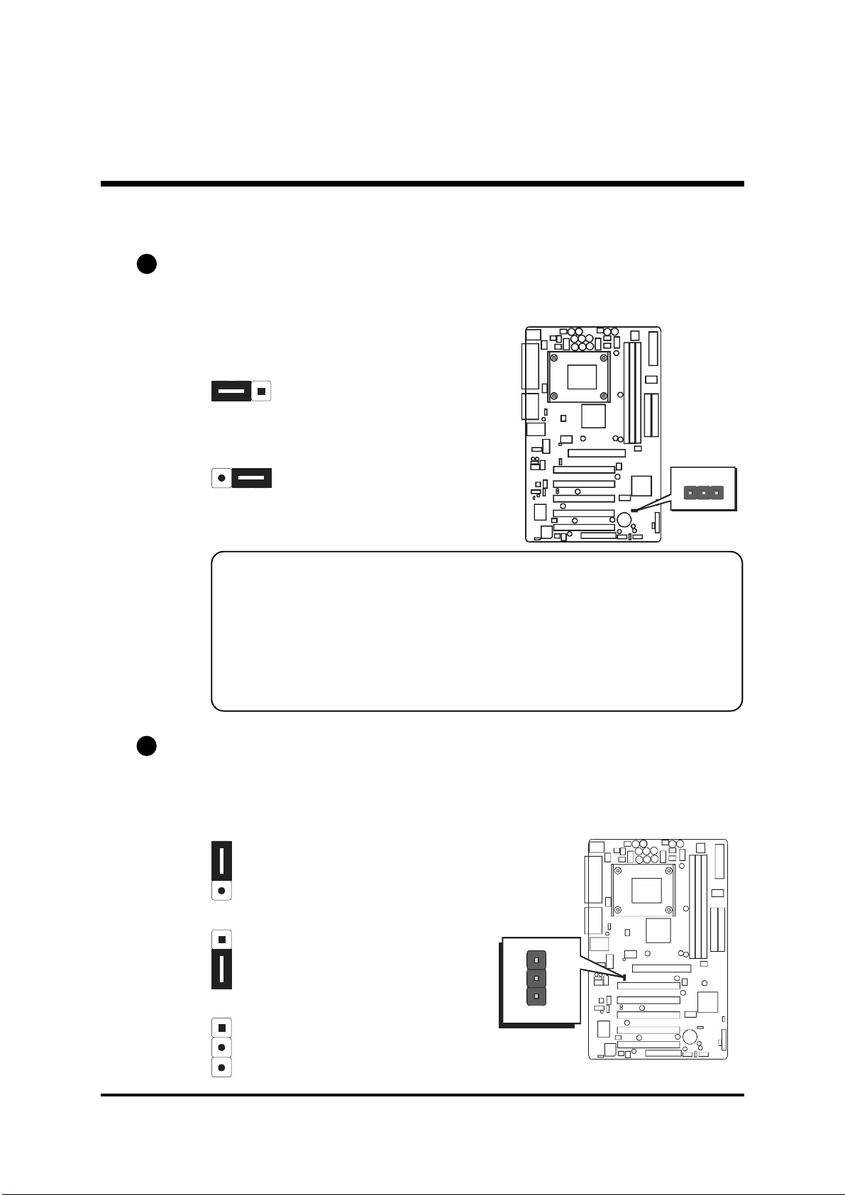
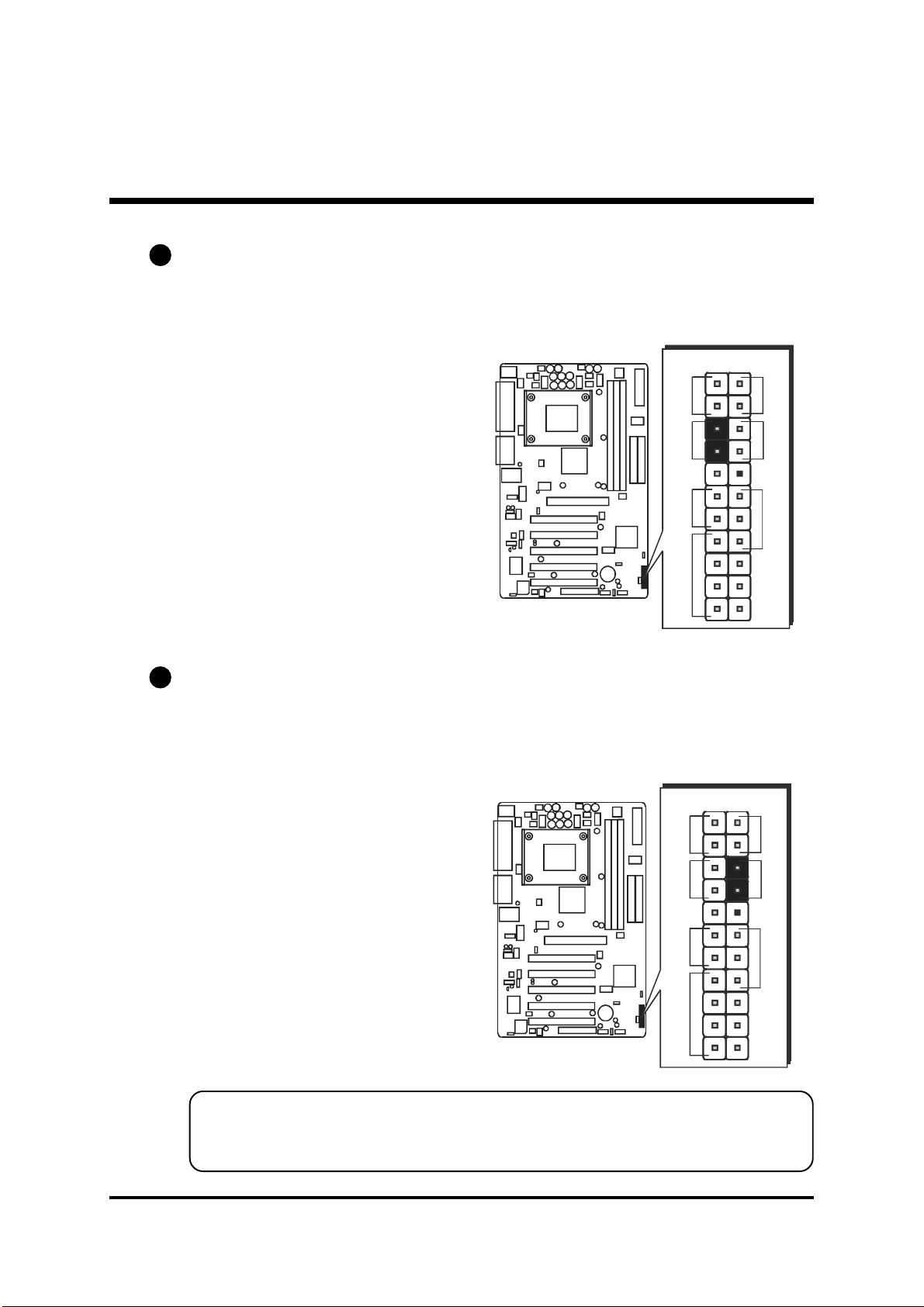
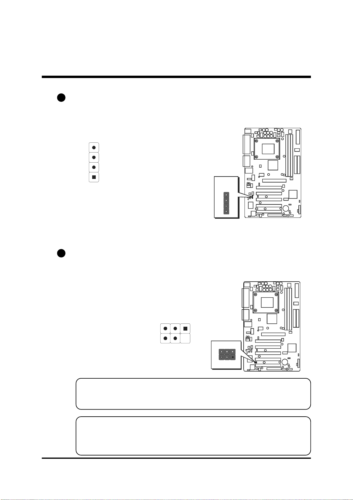
Clear CMOS Setting (JP1)
JP1 is used to clear CMOS data. Clearing CMOS will result in the permanently erasing previous system configuration settings and the restoring original (factory-set) system settings.
Pin 1-2 (Default)
Pin 2-3 (Clear CMOS)
Step 1.Step 1.
Step 1. Turn off the system power (PC-> Off).
Step 1.Step 1.
Step 2.Step 2.
Step 2. Remove ATX Power cable from ATX Power connector.
Step 2.Step 2.
Step 3.Step 3.
Step 3. Remove jumper cap from JP1 pins 1-2.
Step 3.Step 3.
Step 4.Step 4.
Step 4. Place the jumper cap on JP1 pin 2-3 for a few seconds.
Step 4.Step 4.
Step 5.Step 5.
Step 5. Return the jumper cap to pin 1-2.
Step 5.Step 5.
Step 6.Step 6.
Step 6. Plug ATX Power cable into ATX Power connector.
Step 6.Step 6.
Step 7.Step 7.
Step 7. Turn on the system power (PC-> On).
Step 7.Step 7.
A2
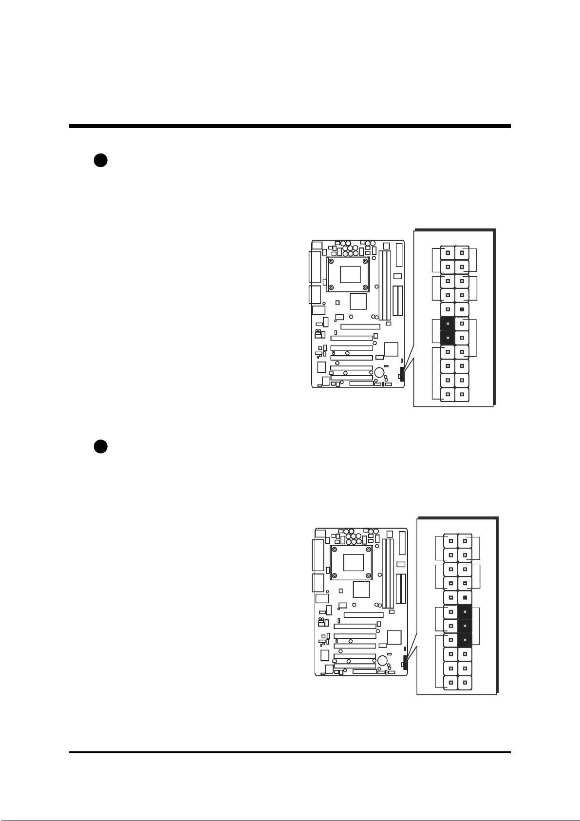
FSB Speed configuration Setting(JP2)
AV49/AV49N provides JP2 to set auto configure frontside bus at 100MHz
and 133MHz. Insert mini-jumper cap on Pin1-2 to identify automatically the
FSB speed.
Pin 1-2 (Auto)
JP1
1
Pin 2-3 (133 MHz)
1
JP2
Off (100 MHz)
- 30 -
Page 33

1
1
A3
1
1
USB Power on Setting(JP3/4)
AV49/AV49N provides jumpers to set USB devices which connect to backepanel tp power-on system from ACPI S3 to S5 stage.
Place jumper cap on JP3(or JP4) pin 1-2 for enabling or disabling USB device
(USB port3~USB port6)power on function.
Pin 1-2
(Disable USB power-on function)
Pin 2-3
(Enable USB power-on function)
A4
BIOS flash protection Setting (JP5)
JP5 is used to protect the BIOS from being unintentionally flashed. Enable this
jumper for protection and disable this jumper when you want to flash the
BIOS.
Pin 1-2( Protected)
1
JP3
1
JP4
Pin 2-3 (Default)Unprotected
JP5
1
- 31 -
Page 34

FF
F
Back-Panel Connectors
FF
B1
PS/2 Keyboard & PS/2 Mouse Connectors
Two 6-pin female PS/2 keyboard & Mouse
connectors are located at the rear panel of
the mainboard. Depending on the computer housing you use (desktop or tower),
the PS/2 Mouse connector is situated at the
top of the PS/2 Keyboard connector when
the mainboard is laid into a desktop, as opposed to a tower where the PS/2 Mouse
connector is located at the right of the PS/
2 Keyboard's. Plug the PS/2 keyboard and
mouse jacks into their corresponding connectors.
B2
Parallel Port Connector
One DB25 female parallel connector is located at the rear panel of the mainboard.
Plug the connection cable from your parallel device (printer, scanner, etc.) into this
connector.
PS/2 Mouse
PS/2 keyboard
Parallel Port
foxconn
B3
COM1/2 Port Connectors
This mainboard can accommodate two
serial device on COM1/2. Attach a serial
device cable to the DB9 serial port COM1/
2 at the back panel of your computer.
B4
Line-Out (Front-Out) Port Connector
Line-Out is a stereo output port through
which the combined signal of all internal
and external audio sources on the board
is output. It can be connected to 1/8-inch
TRS stereo headphones or to amplified
speakers.
- 32 -
COM1 Port
Line-Out Port
COM2 Port
Page 35

B5
Line-In (Rear-Out) Port Connector
Line-In is a stereo line-level input port that
accepts a 1/8-inch TRS stereo plug. It can
be used as a source for digital sound recording, a source to be mixed with the output,
or both.
B6
Mic-In Port Connector
Mic-In is a 1/8-inch jack that provides a
mono input. It can use a dynamic mono or
stereo microphone with a resistance of not
more than 600 Ohms.
B7
MIDI/GAME Port Connector
The MIDI/GAME port is a 15-pin female connector. This port can be connected to any
IBM PC compatible game with a 15-pin Dsub connector.
Line-In Port
Mic-In
MIDI/GAME Port
MIDI Instrument ConnectionMIDI Instrument Connection
MIDI Instrument Connection
MIDI Instrument ConnectionMIDI Instrument Connection
You will need a MIDI adapter to connect a MIDI compatible instrument
to the sound card. The MIDI adapter can in turn be connected to the
Joystick/MIDI port. You will also need the MIDI sequencing software to
run MIDI instruments with your computer etc. into this connector.
B8
USB port1/USB port2 Connectors
This mainboard offers 2 USB ports on back
panel. Plug each USB device jack into an
available USB1/USB2 connector.
B9
LAN Port Connector(AV49N Only)
This mainboard can accommodate one
device on LAN. Attach a 10/100 baseT
cable to the RJ45 at the back-panel of your
computer.
USB Port2
USB Port1
LAN Port
- 33 -
Page 36
FF
F
Front-Panel Connectors
FF
C1
HDD LED Connector (HLED)
Attach the connector cable from the IDE device LED to the 2-pin (HDD LED)
header. The HDD LED lights up whenever an IDE device is active.
D
LE
H
eset
R
1
D
LE
-
/P
D
+
LE
G
N
O
W
P
C2
Green LED/Power LED Connector(GLED/PLED)
This header is dual color LED function.
Dual color LED function is defined by either Green LED or Power LED, the
header can be in these states.
The Green LED indicates that the system is currently in one of the power saving
mode(Doze/Stand by/Suspend). When the system resumes to normal operation mode, the Green LED will go off, power LEN on.
This Power LED will go off during power saving mode.
Attach a 2-pin Green LED/Power LED cable to GLED/PLED header.
I
M
P
E
peaker
S
D
LE
H
eset
R
+
D
LE
P
-
J1
1
D
LE
-
/P
D
+
LE
G
N
O
W
P
- 34 -
I
M
P
E
peaker
S
+
-
J1
D
LE
P
Page 37
C3
Hardware Reset Connector (Reset)
Attach the 2-pin hardware reset switch cable to the (Reset) header. Pressing the
reset switch causes the system to restart.
C4
ATX Power On/Off Switch Connector (PWON)
The Power On/Off Switch is a momentary type switch used for turning on or off
the system ATX power supply. Attach the connector cable from the Power
Switch to the 2-pin (Power ON) header on the mainboard.
D
LE
H
eset
R
I
M
P
E
peaker
S
D
LE
H
eset
R
+
+
+
-
J1
D
LE
/P
D
LE
G
N
O
W
P
D
LE
P
D
LE
/P
D
LE
G
N
O
W
P
1
1
I
M
P
E
peaker
S
Note :Note :
Note : Please notice all the LED connectors are directional. If your chassiss
Note :Note :
+
-
J1
D
LE
P
LED does not light up during running, please simply change to the
opposite direction.
- 35 -
Page 38
C5
EPMI Connector (EPMI)
Hardware System Management Interface (EPMI) header may attach to 2-pin
momentary switch. Press the switch to force system into power saving mode;
press it again to resume back the normal operation situation.
C6
Power LED Connector (PLED)
Attach the 3-pin Power LED connector cable from the housing front panel to
the (Power LED) header on the mainboard. The power LED stays light while the
system is on.
D
LE
H
eset
R
I
M
P
E
peaker
S
+
+
-
J1
D
LE
/P
D
LE
G
N
O
W
P
D
LE
P
1
- 36 -
D
LE
H
eset
R
I
M
P
E
peaker
S
+
+
-
J1
D
LE
/P
D
LE
G
N
O
W
P
D
LE
P
1
Page 39

C7
Speaker Connector (Speaker)
Attach the PC speaker cable from the case to the 4-pin speaker connector
(SPEAKER).
C8
Extended USB Headers (USB2/3)
The headers are used to connect the cable attached to USB connectors
which are mounted on front-panel or back-panel. But the USB cable is optional at the time of purchase.
D
LE
H
eset
R
I
M
P
E
peaker
S
+
+
-
J1
D
LE
/P
D
LE
G
N
O
W
P
D
LE
P
1
24
13
6810
579
Pins Assignment:
1=POWER 2=POWER
3=DATA- 4=DATA5=DATA+ 6=DATA+
7=GND 8=GND
9=KEY 10=NC
1
USB 3 & 4
- 37 -
USB2
USB3
1
USB 5 & 6
Page 40
FF
F
Internal Peripherals Connectors
FF
D1
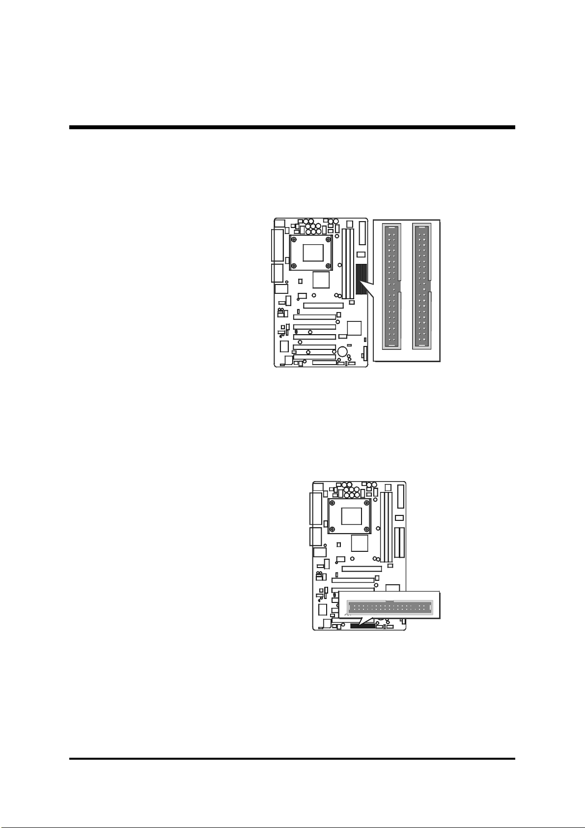
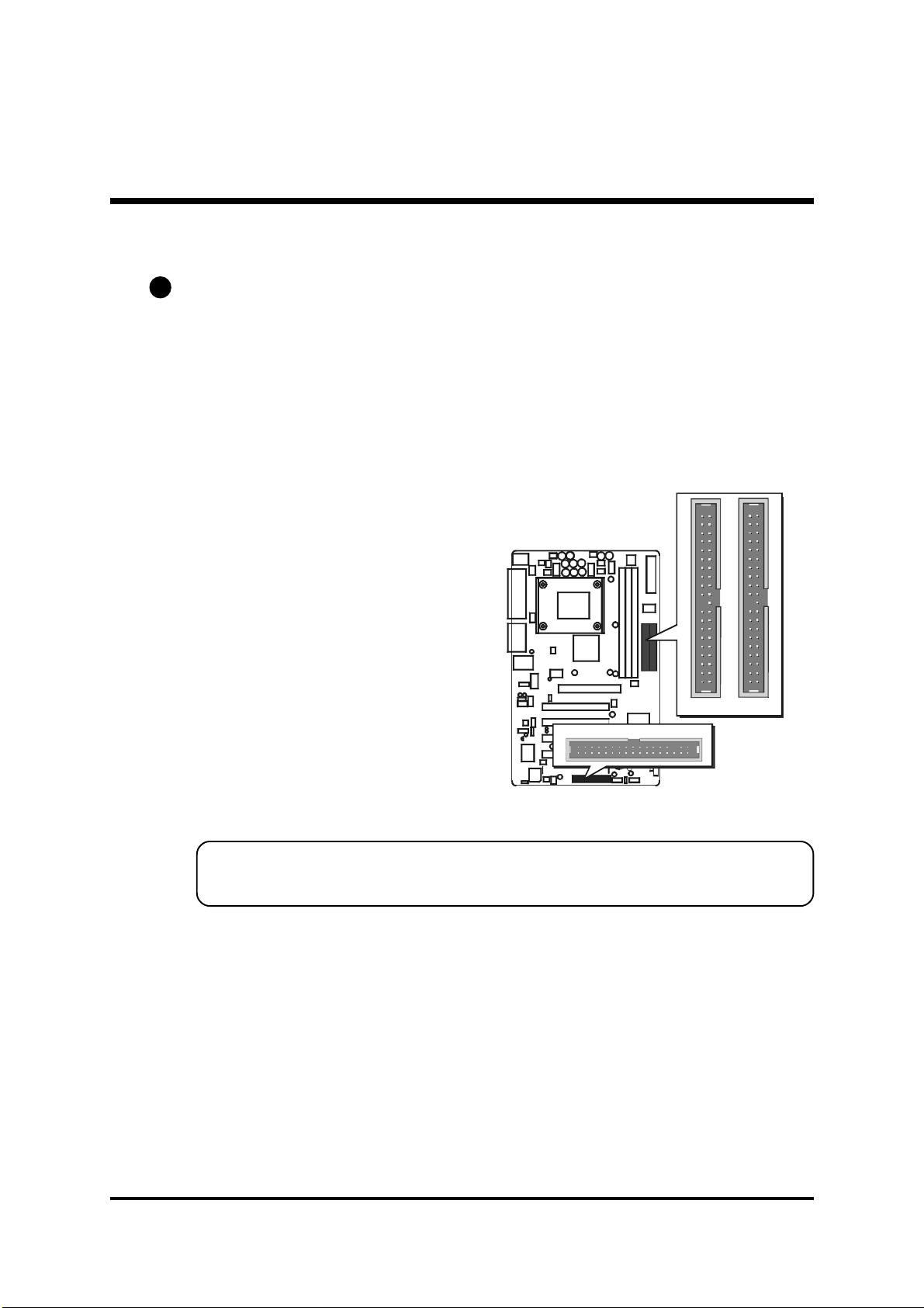
Enhanced IDE and Floppy Connectors
The mainboard features two 40-pin dual-channel IDE device connectors
(IDE1/IDE2) providing support for up to four IDE devices, such as CD-ROM
and Hard Disk Drives (H.D.D.) .
This mainboard also includes one 34-pin floppy disk controller (FDD1) to
accommodate the Floppy Disk Drive (FDD). Moreover, this mainboard
comes with one 80-pin ATA
D. and one 34-pin ribbon cable for F.D.D. connection.
133/100133/100
133/100 ribbon cable to connect to IDE H.D.
133/100133/100
11
IDE 1 IDE 2
FDD1
1
Important:Important:
Important: Ribbon cables are directional, therefore, make sure to always
Important:Important:
connect with the red cable.
- 38 -
Page 41

F F
F
F F
Other Connectors
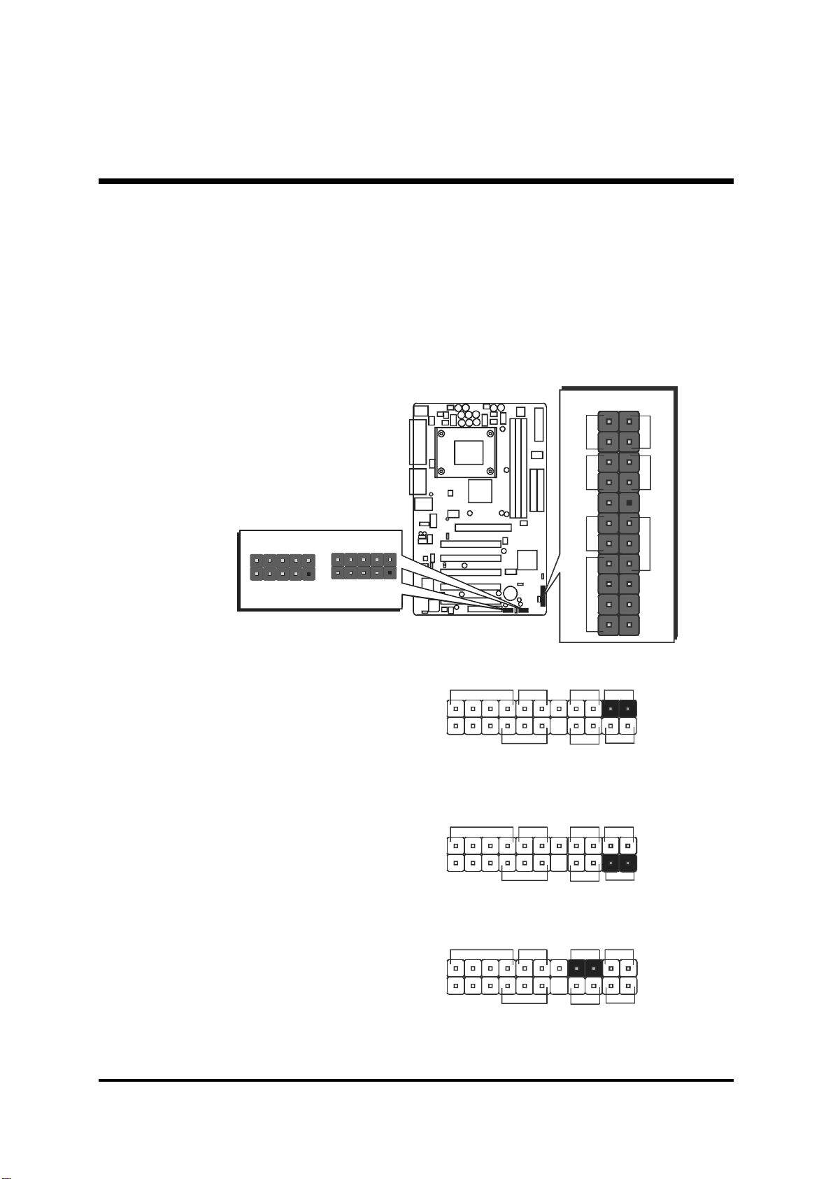
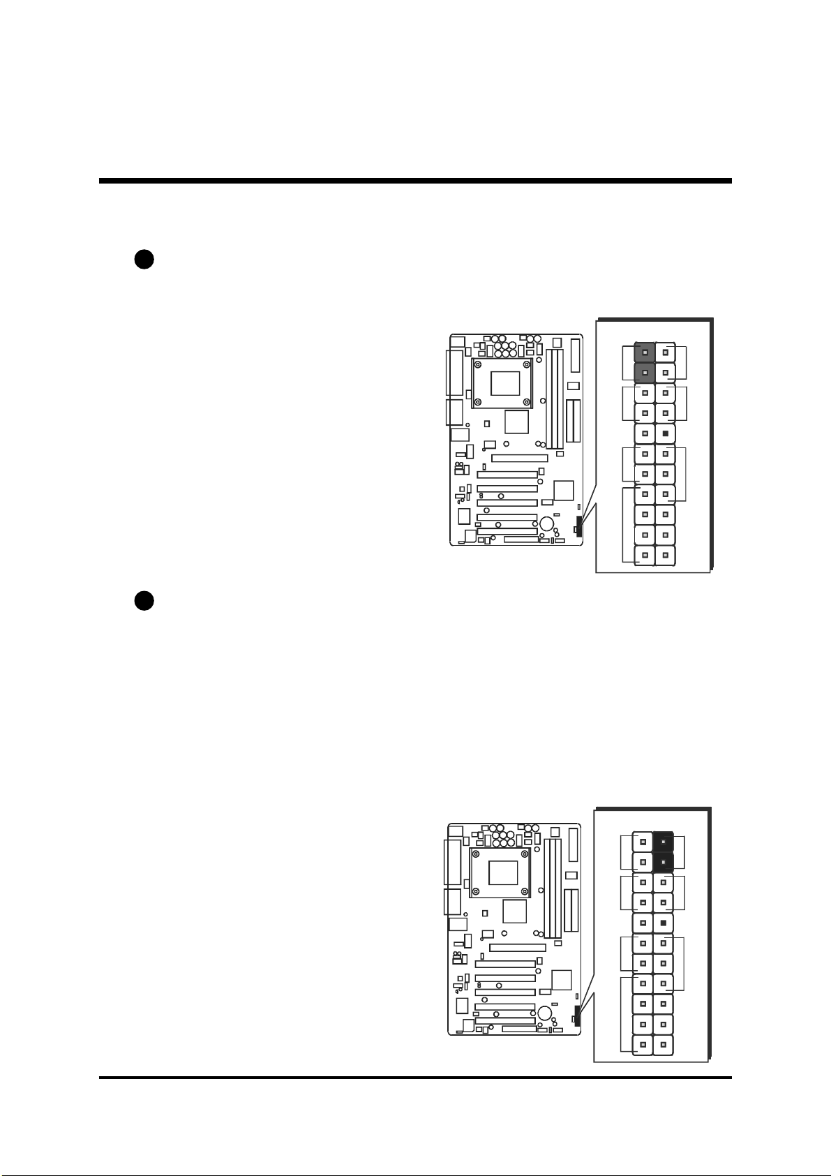
E1
ATX Power Supply Connector (ATX1/ATX2)
This motherboard uses 20-pin standard ATX power header,
and comes with another two headers.
Another is ATX12V with 2X2-pin +12 VPC ATX power supply header.
Please make sure you plug in the right direction.
ATX1
ATX2
ATX2
A traditional ATX system should remain at power off stage when AC power resumes from power failure. In such case, if there is no an UPS to keep power-on, the
kind of design is inconvenient for a network server or workstation.
However, this motherboard implements an AC Power Auto Recovery function to
solve this problem. You may enable the function "PWRON After PWR-Fail" that is
under sub-menu of "Power Mangement Setup " through BIOS setup program.
Note 1:Note 1:
Note 1: The ATX power connector is directional and will not go in unless the guides
Note 1:Note 1:
match perfectly making sure that pin#1 is properly positioned.
Note 2:Note 2:
Note 2: Make sure the latch of the ATX power connector clicks into place to ensure a
Note 2:Note 2:
solid attachment.
Note 3:Note 3:
Note 3: Your ATX power supply must be supplied to ACPI +5V standby power and
Note 3:Note 3:
at least 720mA compatible.
Note 4:Note 4:
Note 4: Make sure your power supply have enough power for higher speed processor
Note 4:Note 4:
installed.
ATX1
- 39 -
Page 42
E2
1
2
3
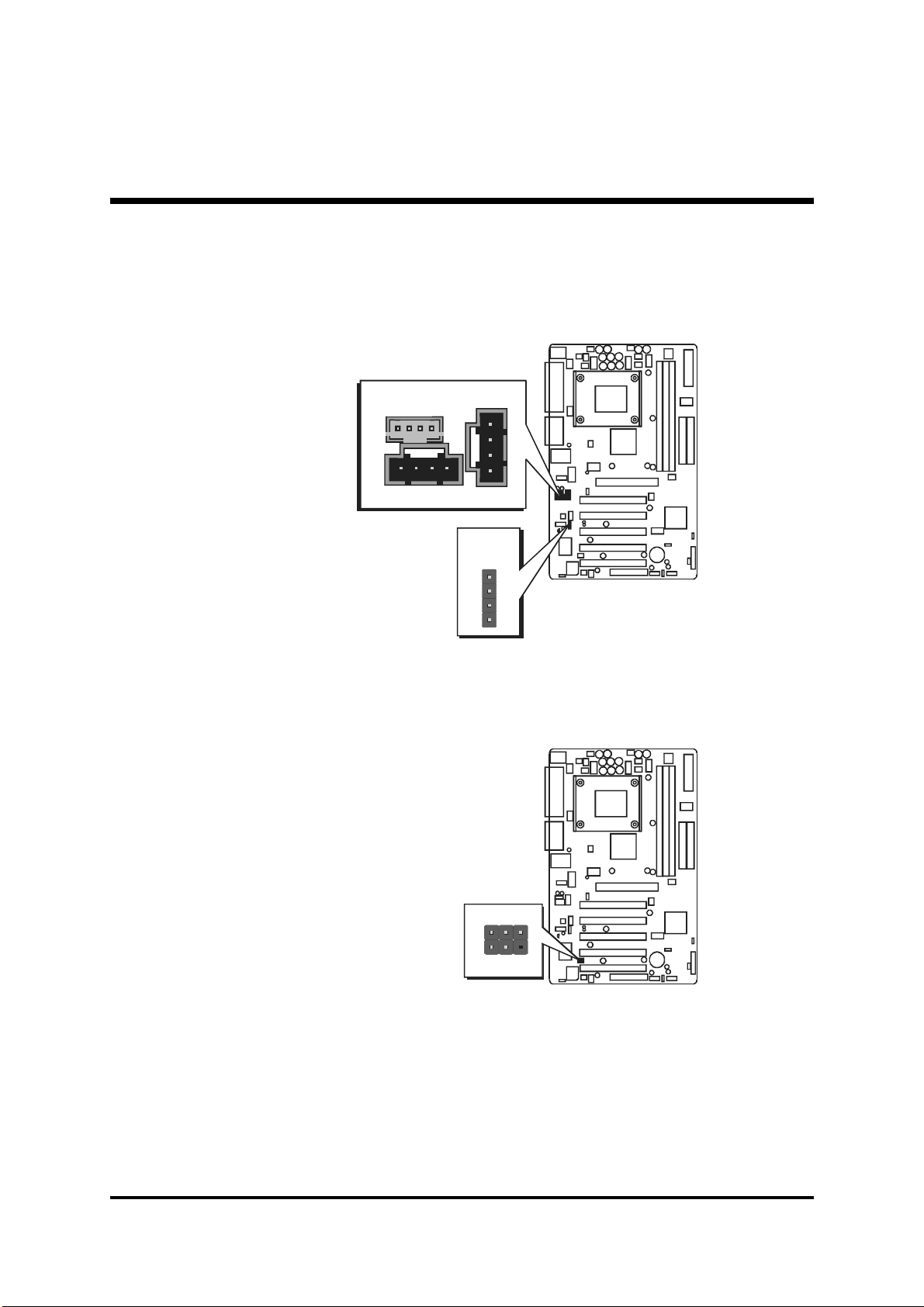
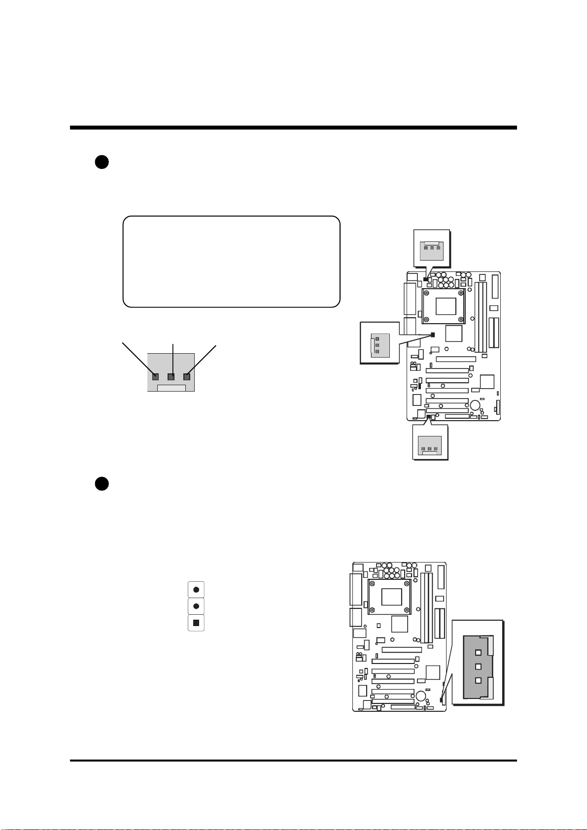
CPU, Chipset, Chassis Fan connectors - FAN1/2/3
The mainboard provides three onboard 12V cooling fan power connectors
to support CPU (FAN1), Chipset (FAN2), or Chassis (FAN3) cooling fans.
Note:Note:
Note:
Note:Note:
Both cable wiring and type of plug may vary
, which depends on the fan maker. Keep in
mind that the red wire should always be
connected to the +12V header and the black
wire to the ground (GND) header.
FA N 1
GND
+12V
SENSE
1
FAN1/FAN2/FAN3 with rotate sense.
E3
Wake-On-LAN Connector (WOL)
Attach a 3-pin connector through the LAN card which supports the Wake-OnLAN (WOL) function. This function lets users wake up the connected system
through the LAN card.
FA N 2
FA N 3
WOL
Pins Assignment:
1=Power 2=GND
3=RING#
1
- 40 -
Page 43

E4
2
175
3
4
6
8
9
10
2
175
3
4
6
8
9
10
143
2
143
2
Front-Panel Audio Header (J5)
This connector is used to attach to Audio equipment embedded into or attached to the case.
Pins Assignment:
1=MIC 2=AGND
3=FLOR 4=LNR
5=FLOL 6=LNL
7=AGND 8=KEY
9=FLOL 10=FNL
Two mini jumpers must be setted on
pin 5-6 and pin 9-10, when this
header is not used.
Front Audio
1
JP5
E5
Audio CD_I NP (White)/ CD_I N Connector (J8) (Black)
Port J7 & J8 is used to attach an audio connector cable from the CD-ROM
drive.
J7 Pin Assignments:
1=CD-GND 2=CD-L
CD_INP
J7
3=CD-GND 4=CD-R
J8
CD_IN
J8 Pin Assignments:
1=CD-L 2=CD-GND
3=CD-GND 4=CD-R
- 41 -
Page 44

E6
9
1046
8
7
5
3
2
1
Audio AUXILIARY_IN Connector (J9) (White)
Port J9 can be used to connect a stereo audio input from CD-ROM, TV-tuner or
MPEG card.
1
2
3
AUX_IN
4
Pin Assignments:
1=AUXL 2=AGND
3=AGND 4=AUXR
J9
E7
SPDIF(J4)
Port J4 can be used to connect special device.
Pin Assignments:
1=+12V 2=VCC
3=N/A 4=SPDIF-OUT
5=SPDIF-IN (Optional) 6=GND
7=N/A 8=N/A
9=KEY 10=GND
SPDIF
1
J4
- 42 -
Page 45
E8
2
153
4
6
Audio Center/Bass_Out Header (J6)
J6
header can be used to connect the cable which attached to bass/center ampli-
fied speakers.
4
3
2
E9
IR Header (J3)
If you have an Infrared device, this mainboard can implement IR transfer
function. To enable the IR transfer function, follow these steps:
Pins Assignment:
1
Pin Assingments:
1=CENTER
2=GND
3=GND
4=BASS
1=NC
2=KEY
3=+5V
4=GND
5=IRTX
6=IRRX
Bass/
Center-Out
J6
IR
JP3
1
1
Note:Note:
Note: Before connect your IR device, please be sure each IR on board pin
Note:Note:
allocation is matchable with the pin of the IR device. Otherwise,
incorrect IR connection may do damage to your IR device.
Step 1.Step 1.
Step 1. Attach the 5-pin infrared device cable to LSIR1.(Refer to the above
Step 1.Step 1.
diagram for IR pin assignment.)
Step 2.Step 2.
Step 2. This mainboard supports Normal, IrDA, ASKIR, or SCR transfer
Step 2.Step 2.
modes.
- 43 -
Page 46

3.3 System Memory Configuration
The AV49/AV49/N mainboard has three 184-pin DIMM banks that allow
you to install from 64MB up to 3GB of system memory.
184-pin184-pin
Each
184-pin DIMM (Dual In-line Memory Module) bank can accommo-
184-pin184-pin
date 64MB, 128MB, 256MB, 512MB, and 1GB of PC1600/PC2100/
PC2700 compliant 2.5V single or double side 64-bit wide data path DDR
SDRAM modules. DIMM slots are arranged in three banks, each memory
bank made of one bank and providing a 64-bit wide data path.
1. Install Memory:
Install memory in any or all of the banks. The combination shown as follows.
tolSMMIDseludoMyromeMytitnauQeludoM
1MMID
2MMID
3MMID
Note:Note:
Note: You do not need to set any jumper to configure memory since the
Note:Note:
MMIDMARDSRDDV5.2nip-481
MMIDMARDSRDDV5.2nip-481
MMIDMARDSRDDV5.2nip-481
BG1dnaBM215,BM652,BM821,BM46
BG1dnaBM215,BM652,BM821,BM46
BG1dnaBM215,BM652,BM821,BM46
1X
1X
1X
BIOS utility can detect the system memory automatically. You can
check the total system memory value in the BIOS Standard CMOS
Setup menu.
2. Upgrade Memory:
You can easily upgrade the system memory by inserting additional DDR
SDRAM modules in available DIMM banks. The total system memory is
calculated by simply adding up the memory in all DIMM banks After
upgrade, the new system memory value will automatically be computed and
displayed in the field "Standard CMOS Setup" of BIOS setup program.
- 44 -
Page 47

4 SOFTW ARE UTILITY
4.1 Mainboard CD Overview
Note: Note:
Note: The CD contents attached in AV49/AV49N mainboard are subject to
Note: Note:
change without notice.
To start your mainboard CD disc, just insert it into your CD-ROM drive and
the CD AutoRun screen should appear. If the AutoRun screen does not
appear, double click or run D:\Autorun.exe (assuming that your CD-ROM
drive is drive D:)
Navigation Bar Description:Navigation Bar Description:
Navigation Bar Description:
Navigation Bar Description:Navigation Bar Description:
Install Mainboard AV49 SoftwareInstall Mainboard AV49 Software
F
Install Mainboard AV49 Software - Installing VIA, Audio device and
Install Mainboard AV49 SoftwareInstall Mainboard AV49 Software
USB2.0 drivers.
Install Mainboard AV49N SoftwareInstall Mainboard AV49N Software
F
Install Mainboard AV49N Software - Installing VIA, Audio device,
Install Mainboard AV49N SoftwareInstall Mainboard AV49N Software
LAN and USB2.0 drivers.
ManualManual
F
Manual - AV49/AV49N Series mainboard user's manual in PDF format.
ManualManual
Link to Shuttle HomepageLink to Shuttle Homepage
F
Link to Shuttle Homepage - Link to shuttle website homepage.
Link to Shuttle HomepageLink to Shuttle Homepage
Browse this CDBrowse this CD
F
Browse this CD - Allows you to see contents of this CD.
Browse this CDBrowse this CD
QuitQuit
F
Quit - Close this CD.
QuitQuit
- 45 -
Page 48

4.2 Install Mainboard Software
Insert the attached CD into your CD-ROM drive and the CD AutoRun screen
should appear. If the AutoRun screen does not appear, double click on
Autorun icon in
SetupSetup
Setup screen.
SetupSetup
Use your pointing device (e.g.mouse) on the
Software"Software"
Software" bar or
Software"Software"
menu.
Mainboard AV49 SoftwareMainboard AV49 Software
The
Mainboard AV49 Software include:
Mainboard AV49 SoftwareMainboard AV49 Software
[4.2.A] [4.2.A]
[4.2.A] Install VIA Driver
[4.2.A] [4.2.A]
[4.2.B] [4.2.B]
[4.2.B] Install Audio Device Driver
[4.2.B] [4.2.B]
[4.2.C] [4.2.C]
[4.2.C] Install USB2.0 Driver
[4.2.C] [4.2.C]
My ComputerMy Computer
My Computer to bring up
My ComputerMy Computer
"Install Mainboard AV49N Software""Install Mainboard AV49N Software"
"Install Mainboard AV49N Software"to run into sub-
"Install Mainboard AV49N Software""Install Mainboard AV49N Software"
Shuttle Mainboard Software Shuttle Mainboard Software
Shuttle Mainboard Software
Shuttle Mainboard Software Shuttle Mainboard Software
"Install Mainboard AV49"Install Mainboard AV49
"Install Mainboard AV49
"Install Mainboard AV49"Install Mainboard AV49
Mainboard AV49N SoftwareMainboard AV49N Software
The
Mainboard AV49N Software include:
Mainboard AV49N SoftwareMainboard AV49N Software
[4.2.A] [4.2.A]
[4.2.A] Install VIA Driver
[4.2.A] [4.2.A]
[4.2.B] [4.2.B]
[4.2.B] Install Audio Device Driver
[4.2.B] [4.2.B]
[4.2.C] [4.2.C]
[4.2.C] Install USB2.0 Driver
[4.2.C] [4.2.C]
[4.2.D] [4.2.D]
[4.2.D] Install LAN Driver
[4.2.D] [4.2.D]
- 46 -
Page 49

4.2.A Install VIA Driver
Insert the attached CD into your CD-ROM drive and the CD AutoRun screen
should appear. If the AutoRun screen does not appear, double click on
Autorun icon in
SetupSetup
Setup screen.
SetupSetup
Use your pointing device (e.g. mouse) to select
install VIA driver.
My ComputerMy Computer
My Computer to bring up
My ComputerMy Computer
Shuttle Mainboard Software Shuttle Mainboard Software
Shuttle Mainboard Software
Shuttle Mainboard Software Shuttle Mainboard Software
Install VIA Driver"Install VIA Driver"
Install VIA Driver" bar to
Install VIA Driver"Install VIA Driver"
A V49
A V49N
Once you made your selection, a Setup window run the installation
automatically.
When the copying files is done, make sure you
installation effect.
rebootreboot
reboot the system to take the
rebootreboot
- 47 -
Page 50

4.2.B Install Audio Device Driver
Select using your pointing device (e.g. mouse) on the
Driver"Driver"
Driver" bar to install audio device driver.
Driver"Driver"
A V49N
Install Audio DeviceInstall Audio Device
Install Audio Device
Install Audio DeviceInstall Audio Device
A V49
Once you made your selection, a Setup window run the installation
automatically.
When the copying files is done, make sure you
installation effect.
rebootreboot
reboot the system to take the
rebootreboot
- 48 -
Page 51

4.2.C Install USB 2.0 Driver
Select using your pointing device (e.g. mouse) on the
Driver"Driver"
Driver" bar to install USB 2.0 driver.
Driver"Driver"
AV49N
Install USB 2.0Install USB 2.0
Install USB 2.0
Install USB 2.0Install USB 2.0
AV49
Once you made your selection, a Setup window run the installation
automatically.
When the copying files is done, make sure you
installation effect.
Note: The WinNT don't need install this driver.Note: The WinNT don't need install this driver.
Note: The WinNT don't need install this driver.
Note: The WinNT don't need install this driver.Note: The WinNT don't need install this driver.
rebootreboot
reboot the system to take the
rebootreboot
- 49 -
Page 52

4.2.D Install LAN Driver(AV49N Only)
Select using your pointing device (e.g. mouse) on the
(AV49N)"(AV49N)"
(AV49N)" bar to install LAN driver.
(AV49N)"(AV49N)"
Install LAN DriverInstall LAN Driver
Install LAN Driver
Install LAN DriverInstall LAN Driver
Once you made your selection, a Setup window run the installation
automatically.
When the copying files is done, make sure you
installation effect.
Note: The WinNT don't need install this driver.Note: The WinNT don't need install this driver.
Note: The WinNT don't need install this driver.
Note: The WinNT don't need install this driver.Note: The WinNT don't need install this driver.
rebootreboot
reboot the system to take the
rebootreboot
- 50 -
Page 53

4.3 View the User's Manual
Insert the attached CD into your CD-ROM drive and the CD AutoRun screen
should appear. If the AutoRun screen does not appear, double click on
Autorun icon in
SetupSetup
Setup screen.
SetupSetup
Select using your pointing device (e.g. mouse) on the
My ComputerMy Computer
My Computer to bring up
My ComputerMy Computer
Shuttle Mainboard Software Shuttle Mainboard Software
Shuttle Mainboard Software
Shuttle Mainboard Software Shuttle Mainboard Software
Manual"Manual"
Manual" bar.
Manual"Manual"
Online Information Online Information
Then
Online Information windows will appear on your screen. Click on
Online Information Online Information
Install Acrobe Reader"Install Acrobe Reader"
the
Install Acrobe Reader" bar if you need to install acrobe reader.
Install Acrobe Reader"Install Acrobe Reader"
Then click on
"AV49/AV49N Manual""AV49/AV49N Manual"
"AV49/AV49N Manual" bar to view user's manual.
"AV49/AV49N Manual""AV49/AV49N Manual"
- 51 -
Page 54

5 BIOS SETUP
AV49/N BIOS ROM has a built-in Setup program that allows users to modify
the basic system configuration. This information is stored in battery-backed
RAM so that it retains the Setup information even if the system power is
turned off.
The system BIOS is managing and executing a variety of hardware related
functions in the system, including:
System date and time
Hardware execution sequence
Power management functions
Allocation of system resources
5.1 Enter the BIOS
To enter the BIOS (Basic Input / Output System) utility, follow these steps:
Step 1.Step 1.
Step 1. Power on the computer, and the system will perform its POST
Step 1.Step 1.
(Power-On Self Test) routine checks.
Step 2.Step 2.
Step 2. Press <Del> key immediately, or at the following message:
Step 2.Step 2.
Press DEL to enter SETUP, or simultaneously press <Ctrl>,
<Alt>, <Esc> keys
Note 1.Note 1.
Note 1. If you miss trains of words meationed in step2 (the message disap-
Note 1.Note 1.
pears before you can respond) and you still wish to enter BIOS
Setup, restart the system and try again by turning the computer OFF
and ON again or by pressing the <RESET> switch located at the
computers front-panel. You may also reboot by simultaneously
pressing the <Ctrl>, <Alt>, <Del> keys.
Note 2.Note 2.
Note 2. If you do not press the keys in time and system does not boot, the
Note 2.Note 2.
screen will prompt an error message, and you will be given the
following options:
Press F1 to Continue, DEL to Enter SetupPress F1 to Continue, DEL to Enter Setup
Press F1 to Continue, DEL to Enter Setup
Press F1 to Continue, DEL to Enter SetupPress F1 to Continue, DEL to Enter Setup
Step 3.Step 3.
Step 3. As you enter the BIOS program, the CMOS Setup Utility will
Step 3.Step 3.
prompt you the Main Menu, as shown in the next section.
- 52 -
Page 55
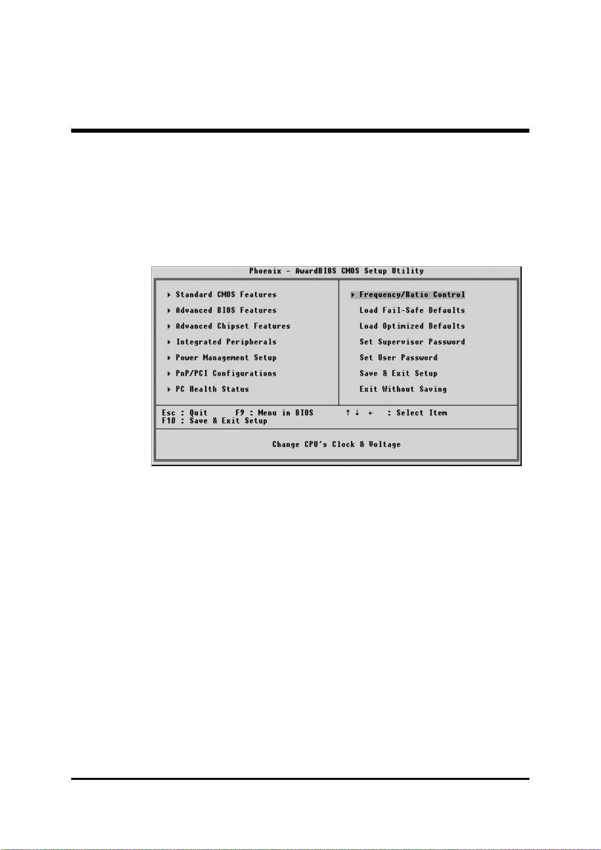
5.2 The Main Menu
Once you enter the AwardBIOS(tm) CMOS Setup Utility, the Main
Menu will appear on the screen. The Main Menu allows you to select
from several setup functions and two exit choices. Use the arrow keys
to select among the items and press <Enter> to accept and enter the
sub-menu.
Note that a brief description of each highlighted selection appears at the
bottom of the screen.
Setup Items
The main menu includes the following main setup categories. Recall
that some systems may not include all entries.
Standard CMOS Features
Use this menu for basic system configuration.
Advanced BIOS Features
Use this menu to set the Advanced Features available on your system.
Advanced Chipset Features
Use this menu to change the values in the chipset registers and optimize your system's performance.
Integrated Peripherals
Use this menu to specify your settings for integrated peripherals.
Power Management Setup
Use this menu to specify your settings for power management.
- 53 -
Page 56

PnP / PCI Configurations
This entry appears if your system supports PnP / PCI.
PC Health Status
This entry shows the current system temperature, Voltage, and FAN
speed.
Frequency/Ratio Control
Use this menu to specify your settings for frequency/Ratio control.
Load Fail-Safe Defaults
Use this menu to load the BIOS default values for the minimal/stable
performance of your system to operate.
Load Optimized Defaults
Use this menu to load the BIOS default values that are factory-set for
optimal performance system operation. While Award has designed the
custom BIOS to maximize performance, the factory has the right to
change these defaults to meet users' needs.
Supervisor / User Password
Use this menu to change, set, or disable supervisor/user password. It
allows you to limit access to the system and Setup, or only to Setup.
Save & Exit Setup
Save CMOS value changes in CMOS and exit from setup.
Exit Without Saving
Abandon all CMOS value changes and exit from setup.
- 54 -
Page 57
@
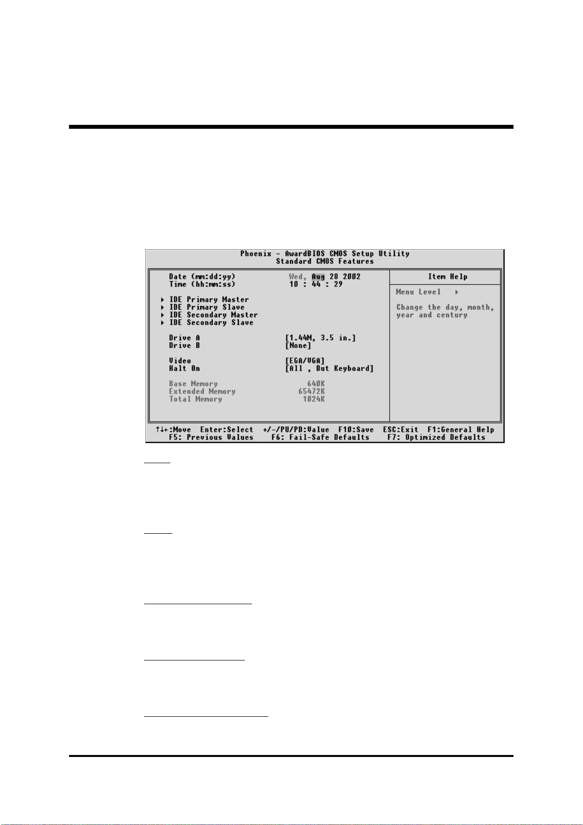
Standard CMOS Features
The items in Standard CMOS Setup Menu are divided into 10
categories. Each category includes no, one or more than one setup
items. Use the arrow keys to highlight the item and then use the
<PgUp> or <PgDn> keys to select the value you want in each item.
DateDate
Date
DateDate
<Month> <DD> <YYYY>
Set the system date. Note that the 'Day' automatically changes when
you set the date.
TimeTime
Time
TimeTime
<HH : MM : SS>
The time is converted based on the 24-hour military-time clock. For
example, 5 p.m. is 17:00:00.
IDE Primary MasterIDE Primary Master
IDE Primary Master
IDE Primary MasterIDE Primary Master
Options are in its sub-menu.
Press <Enter> to enter the sub-menu of detailed options.
IDE Primary SlaveIDE Primary Slave
IDE Primary Slave
IDE Primary SlaveIDE Primary Slave
Options are in its sub-menu.
Press <Enter> to enter the sub-menu of detailed options.
IDE Secondary MasterIDE Secondary Master
IDE Secondary Master
IDE Secondary MasterIDE Secondary Master
Options are in its sub-menu.
Press <Enter> to enter the sub-menu of detailed options.
- 55 -
Page 58

IDE Secondary SlaveIDE Secondary Slave
IDE Secondary Slave
IDE Secondary SlaveIDE Secondary Slave
Options are in its sub menu.
Press <Enter> to enter the sub-menu of detailed options.
Drive A/Drive BDrive A/Drive B
Drive A/Drive B
Drive A/Drive BDrive A/Drive B
Select the type of floppy disk drive installed in your system.
Ø The choice: None, 360K, 5.25 in, 1.2M, 5.25 in, 720K, 3.5 in,
1.44M, 3.5 in, or 2.88M, 3.5 in.
VideoVideo
Video
VideoVideo
Select the default video device.
Ø The choice: EGA/VGA, CGA 40, CGA 80, or MONO.
Halt OnHalt On
Halt On
Halt OnHalt On
Select the situation in which you want the BIOS to stop the POST
process and notify you.
Ø The choice: All Errors, No Errors, All, But Keyboard, All, But
Diskette, or All, But Disk/Key.
Base MemoryBase Memory
Base Memory
Base MemoryBase Memory
Displays the amount of conventional memory detected during boot up.
Ø The choice: N/A.
Extended MemoryExtended Memory
Extended Memory
Extended MemoryExtended Memory
Displays the amount of extended memory detected during boot up.
Ø The choice: N/A.
Total MemoryTotal Memory
Total Memory
Total MemoryTotal Memory
Displays the total memory available in the system.
Ø The choice: N/A.
- 56 -
Page 59

************************************************************************************************************
******************************************************
************************************************************************************************************
IDE Adapters
The IDE adapters control the hard disk drive. Use a separate sub-menu
to configure each hard disk drive.
IDE HDD Auto-DetectionIDE HDD Auto-Detection
IDE HDD Auto-Detection
IDE HDD Auto-DetectionIDE HDD Auto-Detection
Press <Enter> to auto-detect HDD on this channel. If detection is
successful, it fills the remaining fields on this menu.
Ø Press Enter
IDE Primary MasterIDE Primary Master
IDE Primary Master
IDE Primary MasterIDE Primary Master
Selecting 'manual' lets you set the remaining fields on this screen and
select the type of fixed disk. "User Type" will let you select the number
of cylinders, heads, etc., Note: PRECOMP=65535 means
NONE !
Ø The choice: None, Auto, or Manual.
Access ModeAccess Mode
Access Mode
Access ModeAccess Mode
Choose the access mode for this hard disk.
Ø The choice: CHS, LBA, Large, or Auto.
CapacityCapacity
Capacity
CapacityCapacity
Disk drive capacity (Approximated). Note that this size is usually slightly
greater than the size of a formatted disk given by a disk checking
program.
Ø Auto-Display your disk drive size.
The following options are selectable only if the 'IDE Primary Master'
item is set to 'Manual'
CylinderCylinder
Cylinder
CylinderCylinder
Set the number of cylinders for this hard disk.
Ø Min = 0, Max = 65535
HeadHead
Head
HeadHead
Set the number of read/write heads.
Ø Min = 0, Max = 255
PrecompPrecomp
Precomp
PrecompPrecomp
Warning: Setting a value of 65535 means no hard disk.
Ø Min = 0, Max = 65535
- 57 -
Page 60

Landing zoneLanding zone
Landing zone
Landing zoneLanding zone
Set the Landing zone size.
Ø Min = 0, Max = 65535
SectorSector
Sector
SectorSector
Number of sector per track.
Ø Min = 0, Max = 255
************************************************************************************************************
******************************************************
************************************************************************************************************
- 58 -
Page 61
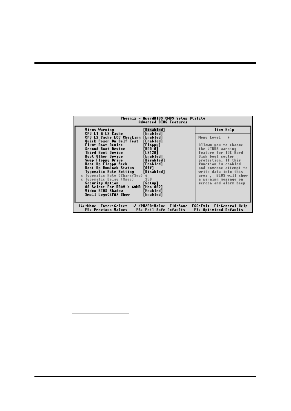
@
Advanced BIOS Features
This section allows you to configure your system for basic operation.
You have the opportunity to select the system's default speed, boot-up
sequence, keyboard operation, shadowing, and security.
Virus WarningVirus Warning
Virus Warning
Virus WarningVirus Warning
Allows you to choose the VIRUS Warning feature for IDE Hard Disk boot
sector protection. If this function is enables and someone attempts to write
data into this area, BIOS will show a warning message on screen, and an
alarm beep.
EnabledEnabled
Enabled Activates automatically when the system boots up, caus-
EnabledEnabled
ing a warning message to appear when anything attempts to access the boot sector or hard disk partition
table.
DisabledDisabled
Disabled No warning message will appear when anything attempts
DisabledDisabled
to access the boot sector or hard disk partition table.
Ø The choice: Enabled or Disabled.
CPU L1 & L2 CacheCPU L1 & L2 Cache
CPU L1 & L2 Cache
CPU L1 & L2 CacheCPU L1 & L2 Cache
This item enables CPU L1 internal and L2 secondary cache to speed up
memory access.
Ø The choice: Enabled or Disabled.
CPU L2 Cache ECC CheckingCPU L2 Cache ECC Checking
CPU L2 Cache ECC Checking
CPU L2 Cache ECC CheckingCPU L2 Cache ECC Checking
When you select Enabled, memory checking is enabled when the
CPU internal L2 cache contains ECC SRAMs.
Ø The choice: Enabled or Disabled.
- 59 -
Page 62

Quick Power On Self TestQuick Power On Self Test
Quick Power On Self Test
Quick Power On Self TestQuick Power On Self Test
This item speeds up Power-On Self Test (POST) after you power on the
computer. If it is set to enabled, BIOS will shorten or skip some check
items during POST.
Ø The choice: Enabled, or Disabled.
First/Second/Third Boot DeviceFirst/Second/Third Boot Device
First/Second/Third Boot Device
First/Second/Third Boot DeviceFirst/Second/Third Boot Device
The BIOS attempts to load the operating system from the devices in the
sequence selected in these items.
Ø The Choice: Floppy, LS120, HDD-0, SCSI, CDROM, , HDD-1,
HDD-2, HDD-3, ZIP100, LAN, or Disabled.
Boot Other DeviceBoot Other Device
Boot Other Device
Boot Other DeviceBoot Other Device
Select Your Boot Device Priority.
Ø The choice: Enabled or Disabled.
Swap Floppy DriveSwap Floppy Drive
Swap Floppy Drive
Swap Floppy DriveSwap Floppy Drive
If the system has two floppy drives, you can swap the logical drive
name assignment.
Ø The choice: Enabled or Disabled.
Boot Up Floppy SeekBoot Up Floppy Seek
Boot Up Floppy Seek
Boot Up Floppy SeekBoot Up Floppy Seek
Seeks disk drives during boot-up. Disabling speed boots up.
Ø The choice: Enabled or Disabled.
Boot Up NumLock StatusBoot Up NumLock Status
Boot Up NumLock Status
Boot Up NumLock StatusBoot Up NumLock Status
Selects power-on state for NumLock.
Ø The choice: Off or On.
Typematic Rate SettingTypematic Rate Setting
Typematic Rate Setting
Typematic Rate SettingTypematic Rate Setting
Keystrokes repeat at a rate determined by the keyboard controller.
When this controller enabled, the typematic rate and typematic delay
can be selected.
Ø The choice: Enabled or Disabled.
Typematic Rate (Chars/Sec)Typematic Rate (Chars/Sec)
Typematic Rate (Chars/Sec)
Typematic Rate (Chars/Sec)Typematic Rate (Chars/Sec)
This item sets how many times the keystroke will be repented in a
second when you hold the key down.
Ø The choice: 6, 8, 10, 12, 15, 20, 24, or 30.
- 60 -
Page 63

Typematic Delay (Msec)Typematic Delay (Msec)
Typematic Delay (Msec)
Typematic Delay (Msec)Typematic Delay (Msec)
Sets the delay time after the key is held down before it begins to repeat
the keystroke.
Ø The choice: 250, 500, 750, or 1000.
Security OptionSecurity Option
Security Option
Security OptionSecurity Option
Select whether the password is required every time the system boots or
only when you enter setup.
SystemSystem
System The system will not boot and access to Setup will be
SystemSystem
denied if the correct password is not entered promptly.
SetupSetup
Setup The system will boot, but access to Setup will be
SetupSetup
denied if the correct password is not entered promptly.
Ø The choice: System or Setup.
Note: To disabled security, select PASSWORD SETTING at Main
Menu, and then you will be asked to enter password. Do not
type anything and just press <Enter>; it will disable security.
Once the security is disabled, the system will boot, and you can
enter Setup freely.
OS Select For DRAM > 64MBOS Select For DRAM > 64MB
OS Select For DRAM > 64MB
OS Select For DRAM > 64MBOS Select For DRAM > 64MB
Selects the operating system that is running with greater than 64MB of
RAM in the system.
Ø The choice: Non-OS2 or OS2.
Video BIOS ShadowVideo BIOS Shadow
Video BIOS Shadow
Video BIOS ShadowVideo BIOS Shadow
Determines whether video BIOS will be copied to RAM. However, it is
optional depending on chipset design. Video Shadow will increase the
video speed.
Ø The choice: Enabled or Disabled.
Small Logo(EPA) ShowSmall Logo(EPA) Show
Small Logo(EPA) Show
Small Logo(EPA) ShowSmall Logo(EPA) Show
This item allows you to enable/disable the EPA Logo.
Ø The choice: Enabled or Disabled.
- 61 -
Page 64

@
Advanced Chipset Features
This section allows you to configure the system based on the specific features
of the installed chipset. This chipset manages bus speeds and access to system memory resources, such as DRAM and the external cache. It also coordinates communications between the conventional ISA bus and the PCI bus.
It states that these items should never need to be altered.
The default settings have been chosen because they provide the best operating conditions for your system. If you discovered that data was being lost
while using your system, you might consider making any changes.
DRAM Clock/Drive ControlDRAM Clock/Drive Control
DRAM Clock/Drive Control
DRAM Clock/Drive ControlDRAM Clock/Drive Control
Options are in its sub-menu.
Press <Enter> to enter the sub-menu of detailed options.
Current FSB FrequencyCurrent FSB Frequency
Current FSB Frequency
Current FSB FrequencyCurrent FSB Frequency
This item show Current CPU Front Side Bus speed.
Current DRAM FrequencyCurrent DRAM Frequency
Current DRAM Frequency
Current DRAM FrequencyCurrent DRAM Frequency
This item show Current DRAM speed.
DRAM ClockDRAM Clock
DRAM Clock
DRAM ClockDRAM Clock
This item allows you to control the DRAM speed.
Ø The Choice: 100MHz, 133MHz, 166MHz, 200MHz or By SPD.
DRAM TimingDRAM Timing
DRAM Timing
DRAM TimingDRAM Timing
This item allows you to select the value in this field, depending on
whether the board using which kind of DDR DRAM.
Ø The Choice: Manual or By SPD.
- 62 -
Page 65

SDRAM CAS LatencySDRAM CAS Latency
SDRAM CAS Latency
SDRAM CAS LatencySDRAM CAS Latency
When synchronous DRAM is installed, the number of clock cycles of
CAS latency depends on the DRAM timing. Do not reset this field from
the default value specified by the system designer.
Ø The Choice: 1.5, 2, 2.5 or 3.
Bank InterleaveBank Interleave
Bank Interleave
Bank InterleaveBank Interleave
The interleave number of internal banks, can be set to 2 way, 4 way
interleave or disabled. For VCM and 16Mb type dram chips, the bank
interleave is fixed at 2 way interleave.
When the dram timing is selected by SPD, it will be set by the value on
SPD of the RAM module(SDR).
Ø The Choice: Disabled, 2 Bank, or 4 Bank.
Precharge to Active (Trp)Precharge to Active (Trp)
Precharge to Active (Trp)
Precharge to Active (Trp)Precharge to Active (Trp)
This item allows you to Precharge Command to Active Command
Period.
Ø The Choice: 2T or 3T.
Active to Precharge (Tras)Active to Precharge (Tras)
Active to Precharge (Tras)
Active to Precharge (Tras)Active to Precharge (Tras)
This item allows you to Active Command to Precharge Command
Period.
Ø The Choice: 6T or 7T.
Active to CMD (Trcd)Active to CMD (Trcd)
Active to CMD (Trcd)
Active to CMD (Trcd)Active to CMD (Trcd)
This item allows you to Active to CMD.
Ø The Choice: 2T or 3T.
DRAM Command RateDRAM Command Rate
DRAM Command Rate
DRAM Command RateDRAM Command Rate
This item allows you to select the DRAM executed rate.
Ø The Choice: 2T Command or 1T Command.
DRAM Burst LenDRAM Burst Len
DRAM Burst Len
DRAM Burst LenDRAM Burst Len
This item allows you to select Dram Burst Length.
Ø The Choice: 4 or 8.
Write Recovery TimeWrite Recovery Time
Write Recovery Time
Write Recovery TimeWrite Recovery Time
This item allows you to select Write Recovery Time.
Ø The Choice: 2T or 3T.
AGP & P2P Bridge ControlAGP & P2P Bridge Control
AGP & P2P Bridge Control
AGP & P2P Bridge ControlAGP & P2P Bridge Control
Options are in its sub-menu.
Press <Enter> to enter the sub-menu of detailed options.
- 63 -
Page 66

AGP Aperture Size (MB)AGP Aperture Size (MB)
AGP Aperture Size (MB)
AGP Aperture Size (MB)AGP Aperture Size (MB)
Select the size of Accelerated Graphics Port (AGP) aperture. The aper-
ture is a portion of the PCI memory address range dedicated to graphics
memory address space. Host cycles that hit the aperture range are
forwarded to the AGP without any translation.
Ø The Choice: 4M, 8M, 16M, 32M, 64M, 128M, or 256M.
AGP ModeAGP Mode
AGP Mode
AGP ModeAGP Mode
This item allows you to select the AGP Mode.
Ø The Choice: 1X, 2X, 4X or 8X.
AGP Driving Control AGP Driving Control
AGP Driving Control
AGP Driving Control AGP Driving Control
This item enables the system to automatically select its output buffer
drive strength or make it manually selectable by an end user.
Ø The Choice: Auto or Manual.
AGP Driving Value AGP Driving Value
AGP Driving Value
AGP Driving Value AGP Driving Value
This item enables an end user to manually select the AGP output buffer
drive strength.
Ø Key in a HEX number: Min = 0000, Max = 00FF.
AGP Fast WriteAGP Fast Write
AGP Fast Write
AGP Fast WriteAGP Fast Write
Enable or Disable the AGP Fast Write faster.
Ø The Choice: Enabled or Disabled.
AGP Master 1 WS WriteAGP Master 1 WS Write
AGP Master 1 WS Write
AGP Master 1 WS WriteAGP Master 1 WS Write
When this item enabled, writing to the AGP(Accelerated Graphics Port)
is executed with one wait state.
Ø The Choice: Enabled or Disabled.
AGP Master 1 WS ReadAGP Master 1 WS Read
AGP Master 1 WS Read
AGP Master 1 WS ReadAGP Master 1 WS Read
When this item enabled, reading from the AGP (Accelerated Graphics
Port) is executed with one wait state.
Ø The Choice: Enabled or Disabled.
DBI Output for AGP Trans(Only support AGP 8X) DBI Output for AGP Trans(Only support AGP 8X)
DBI Output for AGP Trans(Only support AGP 8X)
DBI Output for AGP Trans(Only support AGP 8X) DBI Output for AGP Trans(Only support AGP 8X)
AGP8X transfer mode only. Select Dynamic Bus Inversion function
Enabled or Disbled.
Ø The Choice: Enabled or Disabled.
- 64 -
Page 67

CPU & PCI Bus ControlCPU & PCI Bus Control
CPU & PCI Bus Control
CPU & PCI Bus ControlCPU & PCI Bus Control
Options are in its sub-menu.
Press <Enter> to enter the sub-menu of detailed options.
CPU to PCI Write BufferCPU to PCI Write Buffer
CPU to PCI Write Buffer
CPU to PCI Write BufferCPU to PCI Write Buffer
When this field is Enabled, the writing from CPU to PCI bus is buffered,
to compensate for the speed differences between the CPU and the PCI
bus. When Disabled, the writing is are not buffered and the CPU must
wait until the write is complete before starting another write cycle.
Ø The Choice: Enabled or Disabled.
PCI Master 0 WS WritePCI Master 0 WS Write
PCI Master 0 WS Write
PCI Master 0 WS WritePCI Master 0 WS Write
When this item enabled, writing to the AGP bus is executed with zero
wait state.
Ø The Choice: Enabled or Disabled.
PCI Delay TransactionPCI Delay Transaction
PCI Delay Transaction
PCI Delay TransactionPCI Delay Transaction
The chipset has an embedded 32-bit posted write buffer to support
delay transactions cycles. Select Enabled to support compliance with
PCI specification version 2.1.
Ø The Choice: Enabled or Disabled.
VLink 8X Support VLink 8X Support
VLink 8X Support
VLink 8X Support VLink 8X Support
Enable this item will set VLink 8X transfer mode. Disable it will set
VLink 4X transfer mode.
Ø The Choice: Enabled or Disabled.
Memory HoleMemory Hole
Memory Hole
Memory HoleMemory Hole
In order to improve performance, some space in memory can be
reserved for ISA cards.
Ø The Choice: Disabled or 15M-16M.
System BIOS CacheableSystem BIOS Cacheable
System BIOS Cacheable
System BIOS CacheableSystem BIOS Cacheable
Selecting Enabled allows caching of the system BIOS ROM at F0000hFFFFFh, resulting in better system performance. However, if any program is written to this memory area, a system error may result.
Ø The choice: Enabled or Disabled.
Video RAM CacheableVideo RAM Cacheable
Video RAM Cacheable
Video RAM CacheableVideo RAM Cacheable
Selecting Enabled allows caching of the video RAM , resulting in better
system performance. However, if any program is written to this
memory area, a system error may result.
Ø The Choice: Enabled or Disabled.
- 65 -
Page 68

Delay Prior to ThermalDelay Prior to Thermal
Delay Prior to Thermal
Delay Prior to ThermalDelay Prior to Thermal
This item select the Delay time before thermal controller activate from
temperature too high.
Ø The Choice: 4 Min, 8 Min, 16 Min, or 32 Min.
- 66 -
Page 69
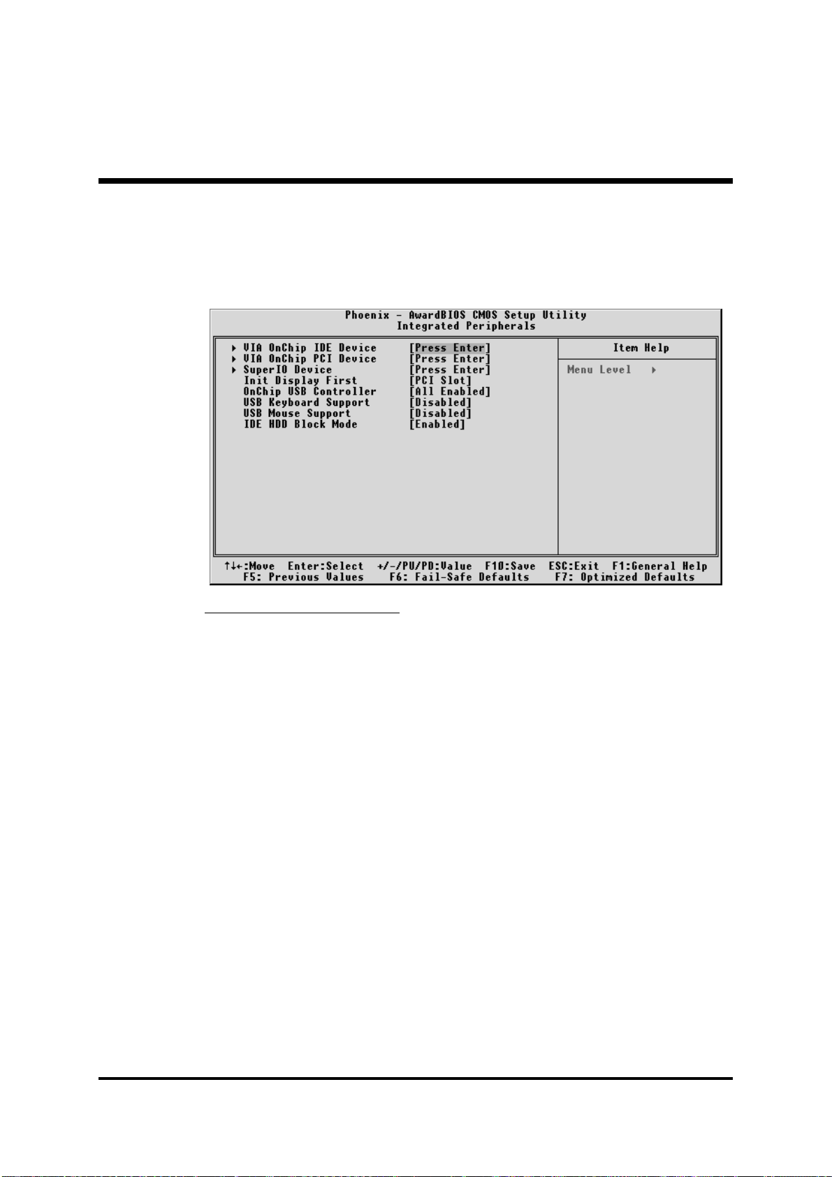
@
Integrated Peripherals
These options display items that defines that the operation of peripheral
VIA OnChip IDE DeviceVIA OnChip IDE Device
VIA OnChip IDE Device
VIA OnChip IDE DeviceVIA OnChip IDE Device
Options are in its sub-menu.
Press <Enter> to enter the sub-menu of detailed options.
components on the system's input/output ports.
OnChip IDE Channel0OnChip IDE Channel0
OnChip IDE Channel0
OnChip IDE Channel0OnChip IDE Channel0
The chipset contains a PCI IDE interface with support to two IDE
channels. Select Enabled to activate the primary IDE interface; select
Disabled to deactivate this interface
Ø The choice: Enabled or Disabled.
OnChip IDE Channel1OnChip IDE Channel1
OnChip IDE Channel1
OnChip IDE Channel1OnChip IDE Channel1
The chipset contains a PCI IDE interface with support to two IDE
channels. Select Enabled to activate the secondary IDE interface; select
Disabled to deactivate this interface
Ø The choice: Enabled or Disabled.
IDE Prefetch ModeIDE Prefetch Mode
IDE Prefetch Mode
IDE Prefetch ModeIDE Prefetch Mode
The onboard IDE drive interfaces support IDE prefetching for faster
drive access. If you install a primary and/or secondary add-on IDE
interface, set this field to Disabled if the interface does not support
prefetching.
Ø The choice: Enabled or Disabled.
- 67 -
Page 70

Primary/Secondary Master/Slave PIOPrimary/Secondary Master/Slave PIO
Primary/Secondary Master/Slave PIO
Primary/Secondary Master/Slave PIOPrimary/Secondary Master/Slave PIO
The four IDE PIO (Programmed Input/Output) fields let you set a PIO
mode (0-4) for each of the four IDE devices that the onboard IDE interface supports. Modes 0 through 4 provide successively increased
performance. In Auto mode, the system automatically determines the
best mode for each device.
Ø The choice: Auto, Mode 0, Mode 1, Mode 2, Mode 3, or Mode 4.
Primary/Secondary Master/Slave UDMAPrimary/Secondary Master/Slave UDMA
Primary/Secondary Master/Slave UDMA
Primary/Secondary Master/Slave UDMAPrimary/Secondary Master/Slave UDMA
Ultra DMA -133/100/66/33 implementation is possible only if your IDE
hard drive supports it and the operating environment includes a DMA
driver (Windows 95 OSR2 or a third-party IDE bus master driver). If both
of your hard drive and your system software support Ultra DMA -133/
100/66/33, select Auto to enable BIOS support.
Ø The choice: Auto or Disabled.
VIA OnChip PCI DeviceVIA OnChip PCI Device
VIA OnChip PCI Device
VIA OnChip PCI DeviceVIA OnChip PCI Device
Options are in its sub-menu.
Press <Enter> to enter the sub-menu of detailed options.
OnBoard AC97 AudioOnBoard AC97 Audio
OnBoard AC97 Audio
OnBoard AC97 AudioOnBoard AC97 Audio
Enables and disables the onboard audio chip. Disable this item if you
are going to install a PCI audio add-on card.
Ø The choice: Auto or Disabled.
VIA-3043 OnChip LANVIA-3043 OnChip LAN
VIA-3043 OnChip LAN
VIA-3043 OnChip LANVIA-3043 OnChip LAN
Enables and disables the onboard LAN. Disable this item if you are
going to install a PCI LAN add-on card.
Ø The choice:Enabled or Disabled.
Onboard Lan Boot ROMOnboard Lan Boot ROM
Onboard Lan Boot ROM
Onboard Lan Boot ROMOnboard Lan Boot ROM
Enables and disables the onboard LAN chip.
Ø The choice:Enabled or Disabled.
Super IO DeviceSuper IO Device
Super IO Device
Super IO DeviceSuper IO Device
Options are in its sub-menu.
Press <Enter> to enter the sub-menu of detailed options.
Onboard FDC ControllerOnboard FDC Controller
Onboard FDC Controller
Onboard FDC ControllerOnboard FDC Controller
Select Enabled if your system has a floppy disk controller (FDC) in-
stalled on the system board and you want to use it. If you install add-on
FDC or the system has no floppy drive, select Disabled in this field.
Ø The choice: Enabled or Disabled.
- 68 -
Page 71

Onboard Serial Port1/Port2Onboard Serial Port1/Port2
Onboard Serial Port1/Port2
Onboard Serial Port1/Port2Onboard Serial Port1/Port2
Select an address and corresponding interrupt for the first and second
serial ports.
Ø The choice: 3E8/IRQ4, 2E8/IRQ3, 3F8/IRQ4, 2F8/IRQ3,Auto, or
Disabled.
UART Mode SelectUART Mode Select
UART Mode Select
UART Mode SelectUART Mode Select
This item allows you to select which mode for the Onboard Serial Port 2.
Ø The choice: IrDA or Normal.
UR2 Duplex ModeUR2 Duplex Mode
UR2 Duplex Mode
UR2 Duplex ModeUR2 Duplex Mode
This item allows you to selects the IR half/full duplex function.
Ø The choice: Full or Half.
Onboard Parallel PortOnboard Parallel Port
Onboard Parallel Port
Onboard Parallel PortOnboard Parallel Port
This item allows you to determine onboard parallel port controller I/O
address setting.
Ø The choice: 378/IRQ7, 278/IRQ5, 3BC/IRQ7, or Disabled.
Parallel Port Mode Parallel Port Mode
Parallel Port Mode
Parallel Port Mode Parallel Port Mode
Select an operating mode for the onboard parallel (printer) port. Select
Normal, Compatible, or SPP unless you are certain your hardware and
software both support one of the other available modes.
Ø The choice: SPP, EPP, ECP, or ECP+EPP.
ECP Mode Use DMAECP Mode Use DMA
ECP Mode Use DMA
ECP Mode Use DMAECP Mode Use DMA
Select a DMA channel for the parallel port for use during ECP mode.
Ø The choice: 1 or 3.
Game Port AddressGame Port Address
Game Port Address
Game Port AddressGame Port Address
This item selects Game Port Address.
Ø The choice: Disable, 201, or 209.
Midi Port AddressMidi Port Address
Midi Port Address
Midi Port AddressMidi Port Address
This item selects Midi Port Address.
Ø The choice: Disable, 330, or 300.
Midi Port IRQMidi Port IRQ
Midi Port IRQ
Midi Port IRQMidi Port IRQ
This item selects Midi Port IRQ.
Ø The choice: 5 or 10.
Init Display FirstInit Display First
Init Display First
Init Display FirstInit Display First
This item allows you to decide to activate PCI Slot or VGA slot first.
Ø The choice: PCI Slot or AGP.
- 69 -
Page 72

OnChip USB ControllerOnChip USB Controller
OnChip USB Controller
OnChip USB ControllerOnChip USB Controller
This should be enabled if your system has a USB installed on the system
board and you want to use it. Even when on chip USB so equipped, if
you add a higher performance controller, you will need to disable this
feature.
Ø The Choice: All Disabled, All Enabled.
USB Keyboard SupportUSB Keyboard Support
USB Keyboard Support
USB Keyboard SupportUSB Keyboard Support
Select Enabled if your system contains a Universal Serial Bus (USB)
controller and you have a USB keyboard.
Ø The Choice: Enabled or Disabled.
USB Mouse SupportUSB Mouse Support
USB Mouse Support
USB Mouse SupportUSB Mouse Support
Select Enabled if your system contains a Universal Serial Bus (USB)
controller and you have a USB Mouse.
Ø The Choice: Enabled or Disabled.
IDE HDD Block ModeIDE HDD Block Mode
IDE HDD Block Mode
IDE HDD Block ModeIDE HDD Block Mode
Block mode is also called block transfer, multiple commands, or multiple sector read/write. If your IDE hard drive supports block mode
(most new drives do), select Enabled for automatic detection of the
optimal number of block read/write per sector the drive can support.
Ø The choice: Enabled or Disabled.
- 70 -
Page 73
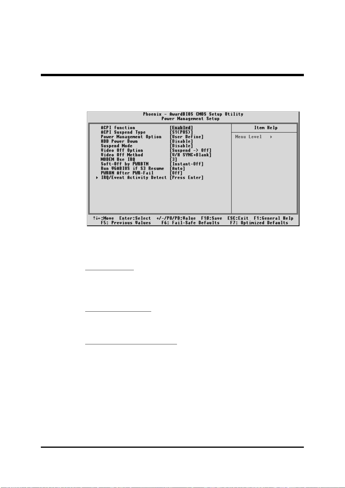
@
Power Management Setup
The Power Management Setup allows you to configure your system to
most effectively saving energy while operating in a manner consistent
with your own style of computer use.
ACPI FunctionACPI Function
ACPI Function
ACPI FunctionACPI Function
This item allows you to enable/disable the Advanced Configuration and
Power Management (ACPI)
Ø The choice: Enabled or Disabled.
ACPI Suspend TypeACPI Suspend Type
ACPI Suspend Type
ACPI Suspend TypeACPI Suspend Type
This item allows you to select sleep state when suspend.
Ø The choice: S1(POS), S3(STR), or S1 & S3.
Power Management OptionPower Management Option
Power Management Option
Power Management OptionPower Management Option
This category allows you to select the type (or degree) of power saving
mode settings.
User DefineUser Define
User Define Allows you to set each mode individually.
User DefineUser Define
HDD Power Down=Disabled or 1min.~15min.
Suspend Mode= Disabled or 1 min ~1 hr.
Ø The choice: User Define, Min Saving, or Max Saving.
Min SavingMin Saving
Min Saving Minimum power management.
Min SavingMin Saving
HDD Power Down=Allows you to set each mode
individually.
Suspend Mode=1 hr.
- 71 -
Page 74

Max Saving Max Saving
Max Saving Maximum power management.
Max Saving Max Saving
HDD Power Down=Allows you to set each mode
individually.
Suspend Mode=1 min.
HDD Power DownHDD Power Down
HDD Power Down
HDD Power DownHDD Power Down
When this item enabled and after the set up time of system inactivity,
the hard disk drive will be powered down while all other devices
remain active.
Ø The choice: Disabled or 1 Min~15 Min.
Suspend ModeSuspend Mode
Suspend Mode
Suspend ModeSuspend Mode
When this item enabled and after the set up time of system inactivity, all
devices except the CPU will be shut off.
Ø The choice: Disabled, 1 Min, 2 Min, 4 Min, 6 Min, 8 Min, 10 Min,
20 Min, 30 Min, 40 Min, or 1 Hour.
Video Off OptionVideo Off Option
Video Off Option
Video Off OptionVideo Off Option
When enabled, this feature allows the VGA adapter to operate in a
power saving mode.
Always OnAlways On
Always On Monitor will remain on during power saving
Always OnAlways On
mode.
Suspend --> OffSuspend --> Off
Suspend --> Off Monitor is blanked when the system enters
Suspend --> OffSuspend --> Off
the Suspend mode.
Ø The choice: Always On , or Suspend ->off.
Video Off MethodVideo Off Method
Video Off Method
Video Off MethodVideo Off Method
This determines the manner in which the monitor is blanked.
V/H SYNC+BlankV/H SYNC+Blank
V/H SYNC+Blank This selection will cause the system to turn off the
V/H SYNC+BlankV/H SYNC+Blank
vertical and horizontal synchronization ports
and write blanks to the video buffer.
Blank Screen Blank Screen
Blank Screen This option only writes blanks to the video buffer.
Blank Screen Blank Screen
DPMS SupportDPMS Support
DPMS Support Initial display power management signaling.
DPMS SupportDPMS Support
Ø The choice: V/H SYNC+Blank, Blank Screen, or DPMS Support.
MODEM Use IRQMODEM Use IRQ
MODEM Use IRQ
MODEM Use IRQMODEM Use IRQ
This determines the IRQ which the MODEM can use.
Ø The choice: 3, 4, 5, 7, 9, 10, 11, or N/A.
- 72 -
Page 75

Soft-Off by PWRBTNSoft-Off by PWRBTN
Soft-Off by PWRBTN
Soft-Off by PWRBTNSoft-Off by PWRBTN
Pressing the power button for more than 4 seconds forces the system to
enter the Soft-Off state when the system has "hung.".
Ø The choice: Instant-Off or Delay 4 Sec.
Run VGABIOS if S3 ResumeRun VGABIOS if S3 Resume
Run VGABIOS if S3 Resume
Run VGABIOS if S3 ResumeRun VGABIOS if S3 Resume
This item Enable/Disable VGA BIOS execution when resume from S3.
It's for some legacy AGP driver compatibility.
Ø The choice: Auto, Yes, or No.
PWRON After PWR- FailPWRON After PWR- Fail
PWRON After PWR- Fail
PWRON After PWR- FailPWRON After PWR- Fail
This allows you to set whether you want your system to reboot after
power has been interrupted.
Ø The choice: Off, On, or Former-Sts.
IRQ/Event Activity DetectIRQ/Event Activity Detect
IRQ/Event Activity Detect
IRQ/Event Activity DetectIRQ/Event Activity Detect
Options are in its sub-menu.
Press <Enter> to enter the sub-menu of detailed options.
USB Resume from S3 USB Resume from S3
USB Resume from S3
USB Resume from S3 USB Resume from S3
Set the item Enabled, users can awaken the system by USB keyboard.
When ACPI Suspend Type item select is S1(POS), then this item can not
showup.
Ø The choice: Disabled or Enabled.
VGAVGA
VGA
VGAVGA
When this item enabled, you can set VGA to awaken the system.
Ø The choice: OFF or ON
LPT & COMLPT & COM
LPT & COM
LPT & COMLPT & COM
When LPT & COM stays On, any activity from one of the listed system
peripheral devices or IRQs wakes up the system.
Ø The choice: NONE, LPT, COM, or LPT/COM
HDD & FDDHDD & FDD
HDD & FDD
HDD & FDDHDD & FDD
When HDD & FDD stays On, any activity from one of the listed system
peripheral devices wakes up the system.
Ø The choice: OFF or ON
PCI MasterPCI Master
PCI Master
PCI MasterPCI Master
When PCI Master stays On, any activity from one of the listed system
peripheral devices wakes up the system.
Ø The choice: OFF, or ON
- 73 -
Page 76

PowerOn by PCI CardPowerOn by PCI Card
PowerOn by PCI Card
PowerOn by PCI CardPowerOn by PCI Card
This item enables/disables the power on function of PCI Card.
Ø The choice: Disabled or Enabled.
Modem Ring ResumeModem Ring Resume
Modem Ring Resume
Modem Ring ResumeModem Ring Resume
When this item enabled, any event occurring Modem Ring/activity of
LAN will awaken a system which has been powered down.
Ø The choice: Disabled or Enabled.
RTC Alarm ResumeRTC Alarm Resume
RTC Alarm Resume
RTC Alarm ResumeRTC Alarm Resume
When this item enabled, your can set the date and time at which the
RTC (real-time clock) alarm awakens the system from Suspend mode.
Ø The choice: Disabled or Enabled.
Data (of Month)Data (of Month)
Data (of Month)
Data (of Month)Data (of Month)
This item selects the alarm date.
Ø Key in a DEC number:Min=0, Max=31.
Resume Time (hh:mm:ss)Resume Time (hh:mm:ss)
Resume Time (hh:mm:ss)
Resume Time (hh:mm:ss)Resume Time (hh:mm:ss)
This item selects the alarm Time.
[hh]
Ø Key in a DEC number:Min=0, Max=23.
[mm/ss]
Ø Key in a DEC number:Min=0, Max=59.
IRQs Activity MonitoringIRQs Activity Monitoring
IRQs Activity Monitoring
IRQs Activity MonitoringIRQs Activity Monitoring
Primary INTRPrimary INTR
Primary INTR
Primary INTRPrimary INTR
Press Enter to on/off the wake up ability of a specified IRQ.
Ø The choice: OFF, or ON.
In the following is a list of IRQ's, Interrupt ReQuests, which can be
exempted much as the COM ports and LPT ports above can. When
an I/O device wants to gain the attention of the operating system, it
signals this by causing an IRQ to occur. When the operating system
is ready to respond to the request, it interrupts itself and performs the
service.
When On mode exist, activity will neither prevent the system from
going into a power management mode nor awaken it.
- 74 -
Page 77

IRQ3 (COM 2 )IRQ3 (COM 2 )
IRQ3 (COM 2 )
IRQ3 (COM 2 )IRQ3 (COM 2 )
IRQ4 (COM 1)IRQ4 (COM 1)
IRQ4 (COM 1)
IRQ4 (COM 1)IRQ4 (COM 1)
IRQ5 (LPT 2)IRQ5 (LPT 2)
IRQ5 (LPT 2)
IRQ5 (LPT 2)IRQ5 (LPT 2)
IRQ6 (Floppy Disk)IRQ6 (Floppy Disk)
IRQ6 (Floppy Disk)
IRQ6 (Floppy Disk)IRQ6 (Floppy Disk)
IRQ7 (LPT 1)IRQ7 (LPT 1)
IRQ7 (LPT 1)
IRQ7 (LPT 1)IRQ7 (LPT 1)
IRQ8 (RTC Alarm)IRQ8 (RTC Alarm)
IRQ8 (RTC Alarm)
IRQ8 (RTC Alarm)IRQ8 (RTC Alarm)
IRQ9 (IRQ2 Redir)IRQ9 (IRQ2 Redir)
IRQ9 (IRQ2 Redir)
IRQ9 (IRQ2 Redir)IRQ9 (IRQ2 Redir)
IRQ10 (Reserved)IRQ10 (Reserved)
IRQ10 (Reserved)
IRQ10 (Reserved)IRQ10 (Reserved)
IRQ11 (Reserved)IRQ11 (Reserved)
IRQ11 (Reserved)
IRQ11 (Reserved)IRQ11 (Reserved)
IRQ12 ( PS / 2 Mouse )IRQ12 ( PS / 2 Mouse )
IRQ12 ( PS / 2 Mouse )
IRQ12 ( PS / 2 Mouse )IRQ12 ( PS / 2 Mouse )
IRQ13 (Coprocessor)IRQ13 (Coprocessor)
IRQ13 (Coprocessor)
IRQ13 (Coprocessor)IRQ13 (Coprocessor)
IRQ14 (Hard Disk)IRQ14 (Hard Disk)
IRQ14 (Hard Disk)
IRQ14 (Hard Disk)IRQ14 (Hard Disk)
IRQ15 (Reserved)IRQ15 (Reserved)
IRQ15 (Reserved)
IRQ15 (Reserved)IRQ15 (Reserved)
Ø The choice: Disabled or Enabled.
- 75 -
Page 78

@
PnP/PCI Configurations
This section describes the configuration of PCI bus system. PCI or
Personal Computer Interconnection is a system which allows I/O
devices to operate at the speed CPU itself keeps when CPU
communicating with its own special components. This section covers
some very technical items, and it is strongly recommended that only
experienced users should make any changes to the default settings.
PNP OS InstalledPNP OS Installed
PNP OS Installed
PNP OS InstalledPNP OS Installed
This item allows you to determine PnP OS is installed or not.
Ø The choice: Yes or No.
Reset Configuration DataReset Configuration Data
Reset Configuration Data
Reset Configuration DataReset Configuration Data
Normally, you leave this field Disabled. Select Enabled to reset
Extended System Configuration Data (ESCD) when you exit from Setup
if you have installed a new device or software and the system
reconfiguration has caused such a serious conflict that the operating
system can not boot.
Ø The choice: Enabled or Disabled .
Resource controlled ByResource controlled By
Resource controlled By
Resource controlled ByResource controlled By
The Award Plug-and-Play BIOS has the capacity to automatically
configure all of the boot and Plug-and-Play compatible devices.
However, this capability means absolutely nothing unless you are using
a Plug-and-Play operating system such as Windows 95. If you set this
field to "manual" , choose specific resources by going into each of the
sub-menu that follows this field (a sub-menu is proceeded by a ">").
Ø The choice: Auto(ESCD) or Manual.
- 76 -
Page 79

IRQ ResourcesIRQ Resources
IRQ Resources
IRQ ResourcesIRQ Resources
When resources are controlled manually, assign each system interrupt a
type, depending on the type of device using the interrupt.
IRQ3/4/5/7/9/10/11/12/14/15 assignedIRQ3/4/5/7/9/10/11/12/14/15 assigned
IRQ3/4/5/7/9/10/11/12/14/15 assigned
IRQ3/4/5/7/9/10/11/12/14/15 assignedIRQ3/4/5/7/9/10/11/12/14/15 assigned
This item allows you to determine the IRQ assigned to the ISA bus and
is not available to any PCI slot. Legacy ISA for devices is compliant with
the original PC AT bus specification; PCI/ISA PnP for devices is compliant with the Plug-and-Play standard whether designed for PCI or ISA
bus architecture.
Ø The choice: PCI Device or Reserved.
PCI/VGA Palette SnoopPCI/VGA Palette Snoop
PCI/VGA Palette Snoop
PCI/VGA Palette SnoopPCI/VGA Palette Snoop
It determines whether the MPEG ISA/VESA VGA Cards can work with
PCI/VGA or not. If you have MPEG ISA/VESA VGA Cards and PCI/
VGA Card worked, Enable this field. Otherwise, please Disable it.
Ø The choice: Enabled or Disabled.
Assign IRQ For VGAAssign IRQ For VGA
Assign IRQ For VGA
Assign IRQ For VGAAssign IRQ For VGA
This item allows the user to set VGA IRQ Routing table Enabled or
Disabled.
Ø The choice: Enabled or Disabled.
Assign IRQ For USBAssign IRQ For USB
Assign IRQ For USB
Assign IRQ For USBAssign IRQ For USB
This item allows the user the option to assign an IRQ to on-board USB
controller. Since the on-board controller is always enabled, if no IRQ is
assigned to it, there will be a question mark report on the sytem device
under Windows95/98.
Ø The choice: Enabled or Disabled.
INT Pin1/2/3/4 AssignmentINT Pin1/2/3/4 Assignment
INT Pin1/2/3/4 Assignment
INT Pin1/2/3/4 AssignmentINT Pin1/2/3/4 Assignment
Names the interrupt request (IRQ) line assigned to PCI 1 throught PCI 4
on system. Activity of selected PCI slot awakens system.
Ø The Choice: Auto, 3, 4, 5, 7, 9, 10, 11, 12, 14, 15.
- 77 -
Page 80
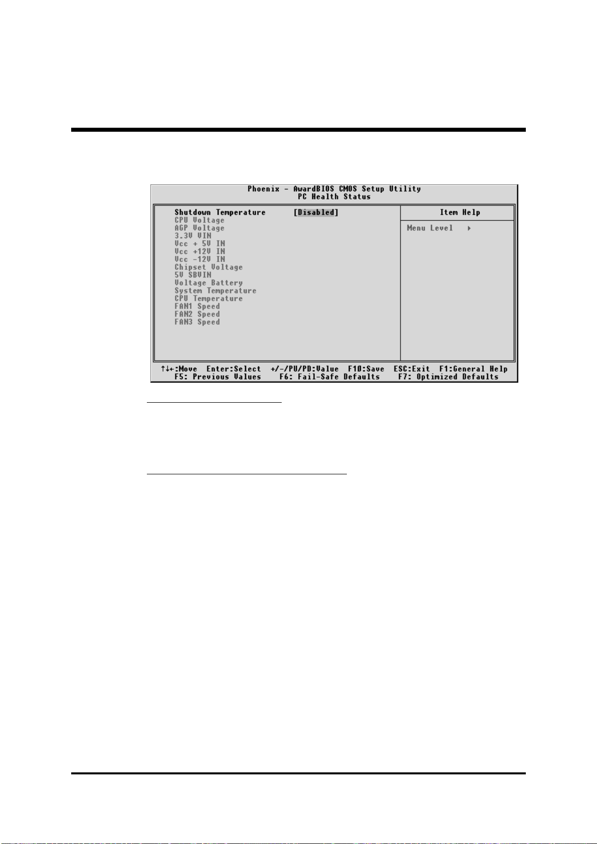
@
PC Health Status
Shutdown TemperatureShutdown Temperature
Shutdown Temperature
Shutdown TemperatureShutdown Temperature
Enables you to set the maximum temperature the system can reach
before powering down.
Ø The choice: Disabled, 60°C/140°F, 65°C/149°F, 70°C/158°F.
System Component CharacteristicsSystem Component Characteristics
System Component Characteristics
System Component CharacteristicsSystem Component Characteristics
These fields provide you with information about the systems current
operating status. You cannot make changes to these fields.
The fields include:
CPU VoltageCPU Voltage
CPU Voltage
CPU VoltageCPU Voltage
AGP VoltageAGP Voltage
AGP Voltage
AGP VoltageAGP Voltage
3.3V VIN3.3V VIN
3.3V VIN
3.3V VIN3.3V VIN
Vcc +5V INVcc +5V IN
Vcc +5V IN
Vcc +5V INVcc +5V IN
Vcc +12V INVcc +12V IN
Vcc +12V IN
Vcc +12V INVcc +12V IN
Vcc -12V INVcc -12V IN
Vcc -12V IN
Vcc -12V INVcc -12V IN
Chipset VoltageChipset Voltage
Chipset Voltage
Chipset VoltageChipset Voltage
5V SBVIN5V SBVIN
5V SBVIN
5V SBVIN5V SBVIN
Voltage BatteryVoltage Battery
Voltage Battery
Voltage BatteryVoltage Battery
System Temperature System Temperature
System Temperature
System Temperature System Temperature
CPU TemperatureCPU Temperature
CPU Temperature
CPU TemperatureCPU Temperature
FAN1 SpeedFAN1 Speed
FAN1 Speed
FAN1 SpeedFAN1 Speed
FAN2 SpeedFAN2 Speed
FAN2 Speed
FAN2 SpeedFAN2 Speed
FAN3 SpeedFAN3 Speed
FAN3 Speed
FAN3 SpeedFAN3 Speed
- 78 -
Page 81
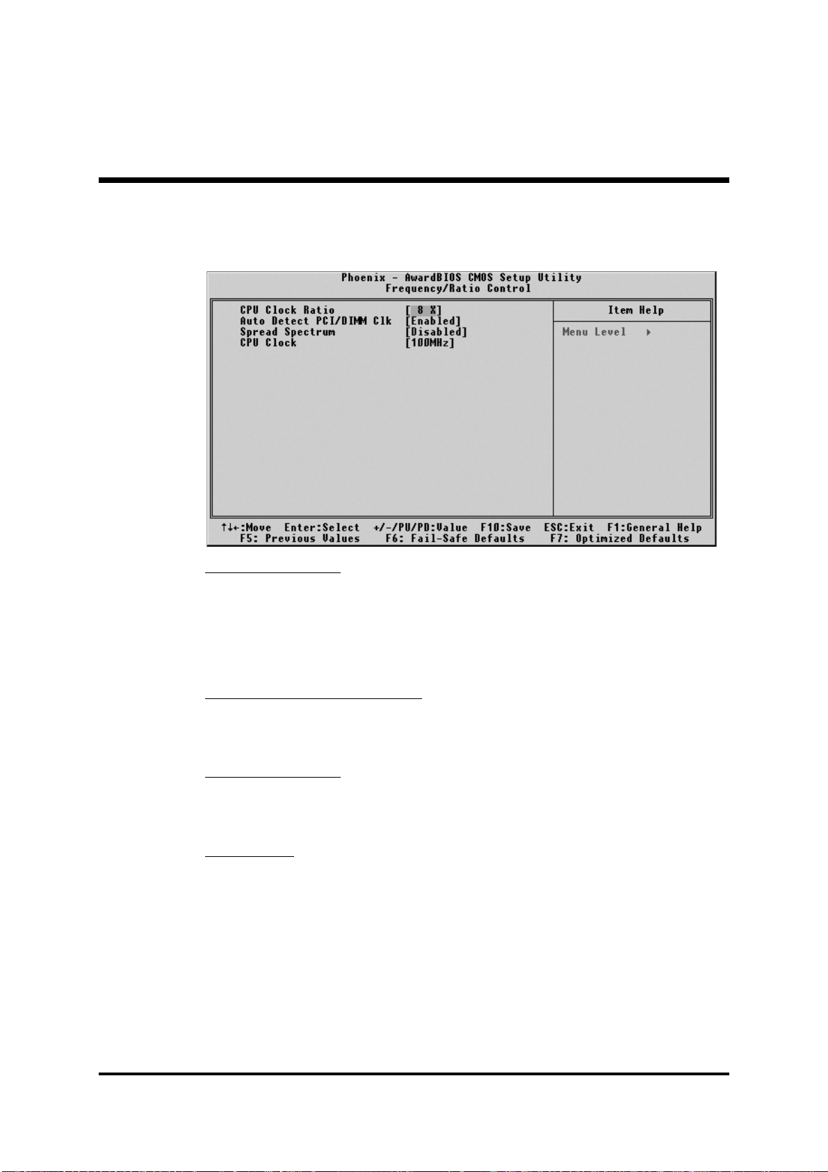
(
Frequency/Ratio Control
CPU Clcok RatioCPU Clcok Ratio
CPU Clcok Ratio
CPU Clcok RatioCPU Clcok Ratio
This item allows the user to adjust CPU Ratio.
Min: 8
Max: 50
Ø Key in a DEC number: (Between Min and Max.)
Auto Detect PCI/DIMM ClkAuto Detect PCI/DIMM Clk
Auto Detect PCI/DIMM Clk
Auto Detect PCI/DIMM ClkAuto Detect PCI/DIMM Clk
This item allows you to enable/disable auto detection DIMM/PCI Clock.
Ø The choice: Enabled, or Disabled.
Spread SpectrumSpread Spectrum
Spread Spectrum
Spread SpectrumSpread Spectrum
This item allows you to enable/disable the spread spectrum modulation.
Ø The choice: Enabled, or Disabled.
CPU ClockCPU Clock
CPU Clock
CPU ClockCPU Clock
This item allows the user to adjust CPU Host Clock from 100 MHz to
160 MHz by 1 MHz step.
Min: 100 MHz
Max: 165 MHz
Ø Key in a DEC number: (Between Min and Max.)
- 79 -
Page 82

@
Load Fail-Safe Defaults
When you press <Enter> on this item, you will get a confirmation
dialog box with a message similar to:
Load Fail-Safe Defaults (Y/N) ? N
Pressing 'Y' loads the BIOS default values for the most stable,
minimal performance system operations.
@
Load Optimized Defaults
When you press <Enter> on this item, you will get a confirmation
dialog box with a message similar to:
Load Optimized Defaults (Y/N) ? N
Pressing 'Y' loads the default values that are factory-set for
optimal performance system operation.
- 80 -
Page 83
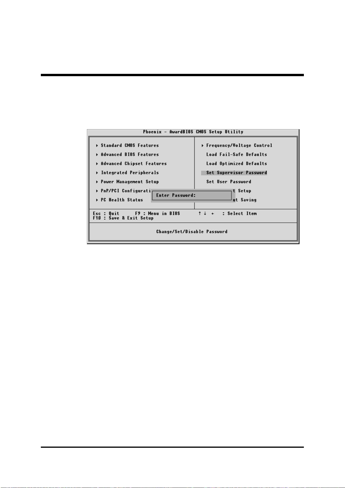
Supervisor/User Password SettingSupervisor/User Password Setting
@
Supervisor/User Password Setting
Supervisor/User Password SettingSupervisor/User Password Setting
You can set either supervisor or user password, or both of them. The
differences between them are:
Supervisor Password and User PasswordSupervisor Password and User Password
Supervisor Password and User Password
Supervisor Password and User PasswordSupervisor Password and User Password
The options on the Password screen menu make it possible to restrict
access to the Setup program by enabling you to set passwords for two
different access modes: Supervisor mode and User mode.
In general, Supervisor mode has full access to the Setup options,
whereas User mode has restricted access to the options. By setting
separate Supervisor and User password, a system supervisor can limit
who can change critical Setup values.
Enter PasswordEnter Password
Enter Password
Enter PasswordEnter Password
Type the password up to eight characters, and press <Enter>. The
password typed now will clear any previously entered password from
CMOS memory. You will be asked to confirm the password. Type the
password again and press <Enter>. You may also press <Esc> to
abort the selection and not enter a password.
To disable password, just press <Enter> when you are prompted to
enter password. A message will confirm the password being disabled.
Once the password is disabled, the system will boot and you can enter
Setup freely.
- 81 -
Page 84

Password DisablePassword Disable
Password Disable
Password DisablePassword Disable
If you select System at Security Option of BIOS Features Setup Menu,
you will be prompted in entering the password whenever the system is
rebooted or you try to enter Setup. If you select Setup at Security Option of BIOS Features Setup Menu, you will be prompted only when
you try to enter Setup.
Warning :Warning :
Warning : Retain a record of your password in a safe place. If you
Warning :Warning :
forget the password, the only way to access the system is
to clear CMOS, please refer to "Clear CMOS" on page 30.
- 82 -
Page 85

@ Save & Exit Setup
Pressing <Enter> on this item asks for confirmation:
Save to CMOS and EXIT (Y/N)? Y
Pressing "Y" stores the selections made in the menus of CMOS - a
special section of memory that stays on after you turn your system off.
The next time you boot your computer, the BIOS configures your
system according to the Setup selections stored in CMOS. After saving
the values the system is restarted again.
@ Exit Without Saving
Pressing <Enter> on this item asks for confirmation:
Quit without saving (Y/N)? Y
This allows you to exit from Setup without storing in CMOS any
change. The previous selections remain in effect. This exits from the
Setup utility and restarts your computer.
- 83 -
 Loading...