

Page 1

AN51R
Socket 754
AMD Athlon
TM
64 Processor
Based DDR MAINBOARD
User's Manual
Page 2

Shuttle® AN51R
Socket 754
AMD Athlon
Based DDR Mainboard
Copyright© 2004 by Shuttle® Inc. All Rights Reserved.
This publication, including all photos, illustrations, and software, is protected under interna-
tional copyright laws, with all rights reserved. Reproducing any of the material contained
herein is prohibited without the consent of the publisher.
Shuttle® Inc. shall not be liable for any incidental or consequential damages resulting from the
performance or use of this product.
TM
64 Processor
Copyright
Disclaimer
This company makes no representations or warranties regarding the contents of this manual.
Information in this manual has been carefully checked for reliability; however, no guarantee is
given as to the correctness of the contents. In the interest of continued product improvement,
this company reserves the right to revise the manual or include changes in the specifications
of the product described within it at any time without notice and without obligation to notify any
person of such revision or changes. The information contained in this manual is provided for
general use by the customers.
Trademarks
Shuttle is a registered trademark of Shuttle Inc.
NVIDIA is a registered trademark of NVIDIA Corporation.
AMD, Athlon TM 64 is registered trademarks of AMD Corporation.
PS/2 is a registered trademark of IBM Corporation.
AWARD is a registered trademark of Award Software Inc.
Microsoft and Windows are registered trademarks of Microsoft Corporation.
General Notice: Other product names used in this manual are ascribed to their respective
owners and acknowledged.
MA10
Page 3
WARNING
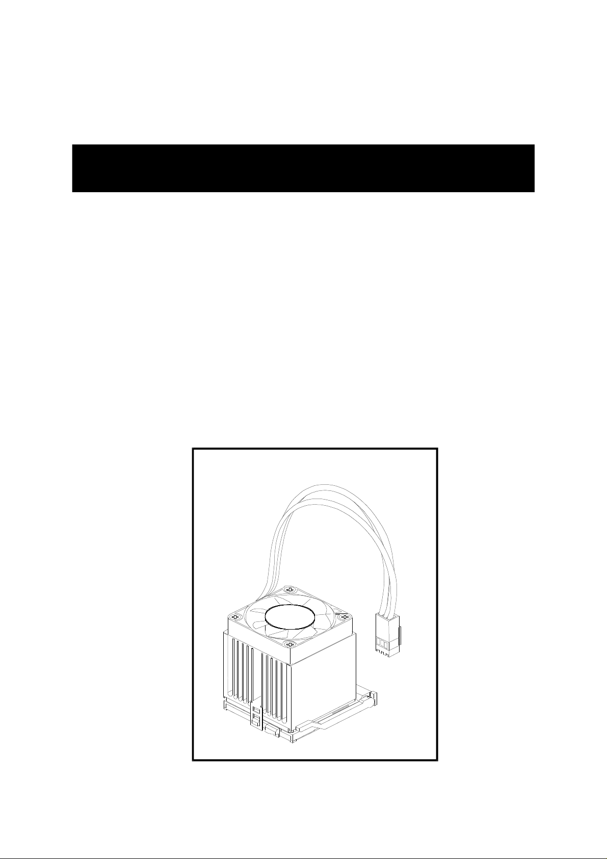
Thermal issue is highly essential for processors with a speed of 600MHz and above.
Hence, we recommend you to use the CPU fan qualified by AMD or motherboard
manufacturer. Meanwhile, please make sure CPU and fan are securely fastened well.
Otherwise, improper fan installation not only gets system unstable but also could
damage both CPU and motherboard because insufficient thermal dissipation.
If you would like to know more about thermal topic please see AMD website for
detailed thermal requirement through the address:
http://www.amd.com
Page 4
NOTICE
If you’ve changed your CPU or overclocked your system, the system may fail to boot up,
even with a Clear CMOS jumper physically resetted. The reason is that NVIDIA’s new
nForce2 chipset introduces a way to reset a Clear CMOS jumper without removing a
chassis. Please follow the steps listed below:
1. Turn off your computer and unplug the power cable. Reconnect it after 30 seconds;
2. Press <Insert > and then press your computer’s start button. Continue holding <Insert>
until the system begins the POST (Power-On Self Test);
3. Immediately press <Del> to enter the BIOS;
4. Select ‘Load Optimized Defaults’ to return your system to a bootable condition; then
select ‘SAVE to CMOS and EXIT’;
5. Reboot your system.
Moreover, if your system fails to boot up after you reset the CPU FSB, select “SAVE to
CMOS and EXIT” in the BIOS. After the system restarts, there is on screen a message
warning you not to reset or turn off your computer:
Warning! New setting is updating now
Do not Reset or Shutdown the system
Your system works after the BIOS is updated.
Page 5

Statement of Shuttle Mainboard via the EMI Test
Shuttle mainboards have been via the EMI test in terms of series of regulations: EN55022/
CISPR22/AS/NZS3548 Class B, EN55024 (1998/AS/NZS), EN4252.1 (1994), EN61000, ANSI
C63.4 (1992), CFR47 Part 15 Subpart B, and CNS13438 (1997). The items tested are illustrated as follows:
(A) Voltage: AC 110V/60HZ & AC 230V/50HZ
(B) Tested Product Information:
Product Name: PC Mainboard
Status: Sample
Model Name: AN51R
S/N: N/A
CPU:
External Frequency: 200 MHz 3000+/ 3200+
Mouse Port: one port with 6 pins
Keyboard Port: one port with 6 pins
Parallel Port: one port with 25 pins
Serial Port: one ports with 9 pins respectively
1394 Port: one port with 6 pins
Mic-In & Center/Bass & Line-In & Rear-Out & SPDIF-Out & Front-Out Ports : one port
for each
LAN Port: one port with 8 pins (10Mbps/ 100Mbps)
USB Port: four ports with 4 pins respectively
DIMM Memory (optional): DDR 400 256 MB*2
Power Cable: Detachable and Shielded (with a GND pin)
Monitor:CRT
Maximum Resolution: 1280 X 1024 V:60Hz
All CPUs have completely been tested, and values offered by the worst EMI combination of
CPU external frequency are listed as follows:
Test Mode
1
(C) Remedy for the Tested Product & Its EMI Interference:
Remedy: N/A
EMI Interference:
External Frequency
200 MHz
Crystal: 14.318MHz(X1)/25.00 KHz(X9)/32.768 MHz(X2)/24.576 MHz(X3)/
25.000 MHz(X6)/24.576 MHz(X7)
Clock Generator: Zu1
CPU
3200+
Page 6
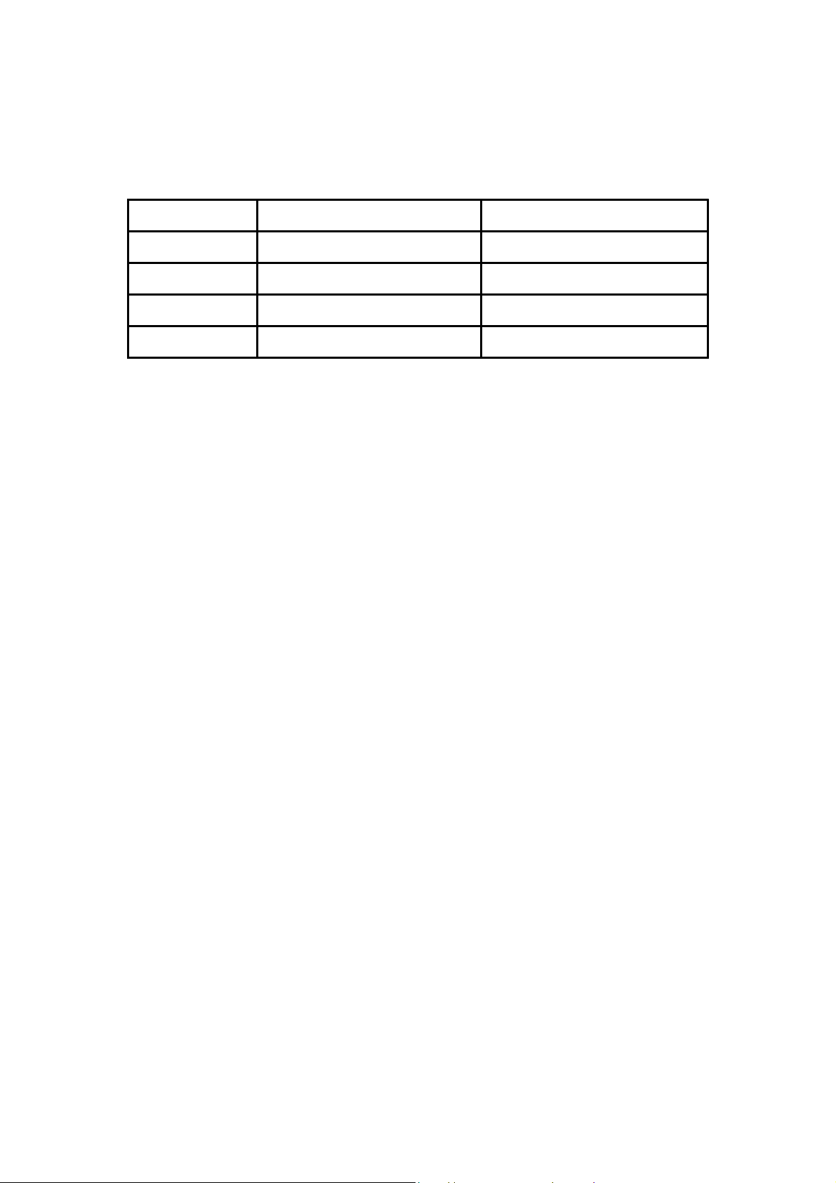
(D) Supported Host Peripherals:
Host Peripheral Product Name Model Name
#1 Case AN51R
#2 Power Supply (300W) ENP-0730
#3 Maxtor HDD (40GB) D740X-6L
#4 CODE DVD Player DVD-116
(E) Notices for Assembling Computers:
1. Cases should be made of iron or other metal that has good electric conductivity.
2. Cylinders in a case should be made of metal, and as having a mainboard mounted
in a case, make sure screws are all utilized and fastened on a mainboard.
3. An I/O shielding should be contacted with I/O metallic parts of a mainboard.
4. Cables should appropriately be arranged and fixed in a case. Follow instructions:
Ø Leave IDE cables not crossed upon CPU and SDRAM;
Ø Leave power cables minimum in length, and not crossed upon a mainboard;
Ø Leave CPU fan cables minimum in length, and not near CPU;
Ø Leave cables on panels and other spare cables tied in a computer case.
5. Make sure an EMI shielding attached to a case has properly been installed.
6. Make sure a 5.25" or 3.5" FDD and screws are fastened to an EMI shielding.
7. Make sure a case is closely in contact with EMI connected points.
8. Make sure there is no cleft in a case which is not deformed.
9. Make sure a PCI or AGP door is bound to a case.
10. Make sure cables of other devices (fans or some others) are fixed in a case.
Page 7

Important Safety Information
SAFETY INSTRUCTIONS
1. Please read these safety instructions carefully.
2. Please keep this User‘s Manual for later reference.
3. Please disconnect this equipment from AC outlet before cleaning. Don‘t use liquid
or sprayed detergent for cleaning.
4. For pluggable equipment, the socket-outlet shall be installed near the equipment
and shall be easily accessible.
5. Please keep this equipment from humidity.
6. Lay this equipment on a reliable surface when install. A drop or fall could cause injury.
7. Do not leave this equipment in an environment unconditioned, it may damage the
equipment.
8. The openings on the enclosure are for air convection hence Protect the equipment
from overheating. DO NOT COVER THE OPENINGS.
9. Make sure the voltage of the power source when connect the equipment to the
power outlet.
10. Place the power cord such a way that people can not step on it. Do not place anything
over the power cord. The power cord must be rated for the product and for the voltage
and current marked on the product’s electrical ratings label. The voltage and current
rating of the cord should be greater than the voltage and current rating marked on the
product.
11. All cautions and warnings on the equipment should be noted.
12. If the equipment is not use for long time, disconnect the equipment from mains to avoid
being damaged by transient over-voltage.
13. Never pour any liquid into ventilation openings, this could cause fire or electrical shock.
14. CAUTION: The computer is provided with a battery-powered real-time clock circuit.
There is a danger of explosion if battery is incorrectly replaced.
Replace only with same or equivalent type recommended by the manufacture.
Discard used batteries according to the manufacturer’s instructions.
CAUTION : RISK OF EXPLOSION IF BATTERY IS REPLACED BY AN
INCORRECT TYPE. DISPOSE OF USED BATTERIES
ACCORDING TO THE INSTRUCTIONS
15. THE COMPUTER IS PROVIDED WITH CD DRIVES COMPLY WITH APPROPRIATE SAFETY STANDARDS INCLUDING IEC 60825.
CLASS 1 LASER PRODUCT
Page 8

TABLE OF CONTENTS
WHAT'S IN THE MANUAL.................................................................... 4
Quick Reference............................................................................................... 4
About This Manual ........................................................................................... 4
1 INTRODUCTION ................................................................................ 5
1.1 TO DIFFERENT USERS ............................................................................. 5
FIRST-TIME DIY SYSTEM BUILDER............................................................ 5
EXPERIENCED DIY USER ......................................................................... 5
SYSTEM INTEGRATOR............................................................................... 5
1.2 ITEM CHECKLIST: ...................................................................................... 6
2 FEATURES ........................................................................................ 8
2.1 SPECIFICATIONS ....................................................................................... 8
3 HARDWARE INSTALLATION.......................................................... 12
3.1 STEP-BY-STEP INSTALLATION............................................................... 12
STEP 1 Install the CPU .............................................................................. 13
STEP 2 Set Jumpers ................................................................................. 14
STEP 3 Install DDR SDRAM System Memory............................................ 14
STEP 4 Install Internal Peripherals in System Case .................................... 15
STEP 5 Mount the Mainboard on the Computer Chassis............................ 16
STEP 6 Connect Front Panel LEDs/Switches/Speaker/USBs .................... 17
STEP 7 Connect IDE ,Floppy Disk Drives................................................. 18
STEP 8 Connect Other Internal Peripherals................................................ 19
STEP 9 Connect the Power Supplies......................................................... 21
STEP 10 Install Add-on Cards in Expansion Slots ...................................... 21
STEP 11 Connect External Peripherals to Back Panel ............................... 22
STEP 12 System Boot Up For the First-Time ............................................. 23
STEP 13 Install Drivers & Software Components ....................................... 24
3.2 JUMPER SETTINGS ................................................................................. 25
JUMPERS & CONNECTORS GUIDE........................................................ 26
Jumpers
Clear CMOS Setting (JP18)...................................................................... 28
Giga LAN Setting (JP21) .......................................................................... 29
1394 Setting (JP22).................................................................................. 29
- 1 -
Page 9

Back Panel Connectors
PS/2 Mouse & PS/2 Keyboard Port Connectors ........................................ 30
Parallel Port Connector.............................................................................. 30
COM1 Port Connector ............................................................................... 30
Clear CMOS Button ................................................................................... 30
SPDIF-In Connector.................................................................................. 30
IEEE 1394 Connector................................................................................ 31
USB Port Connectors ............................................................................... 31
Gigabit LAN Port Connector....................................................................... 31
Mic-In Port Connector ................................................................................ 31
Center/Bass Port Connector ...................................................................... 31
Line-In Port Connector ............................................................................... 32
Rear-Out Port Connector ........................................................................... 32
SPDIF-Out Port Connector......................................................................... 32
Front-Out Port Connector ........................................................................... 32
Front Panel Connectors
HDD LED Connector (HLED) .................................................................... 33
Green LED Connector (GLED) .................................................................. 33
Hardware Reset Connector (RST).............................................................. 34
ATX Power On/Off Switch Connector (PWON) ........................................... 34
EPMI Connector (EPMI)............................................................................. 35
Power LED Connector (PLED) .................................................................. 35
Speaker Connector (SPEAKER) ............................................................... 35
Internal Peripheral Connectors
Enhanced IDE and Floppy Connectors (IDE1/IDE2 & FLP1) ...................... 36
Serial ATA Connectors (SATA #1~4) .......................................................... 36
Other Connectors
ATX Power Supply Connectors (ATX1/CN8) .............................................. 37
CPU and System Fan Connectors (FAN1/2/3)............................................ 38
IR Header (JP8)......................................................................................... 38
Audio CD_IN Connectors (CN4/CN5) ........................................................ 39
Audio AUX_IN Connector (CN6) ................................................................ 39
Extended USB Headers (JP7/JP20) .......................................................... 40
Front Panel Audio Header (JP11)............................................................... 40
- 2 -
Page 10

IEEE 1394 Connector (JP15)..................................................................... 41
Power Button (SW1) .................................................................................. 41
Reset Button (SW2) ................................................................................... 41
3.3 SYSTEM MEMORY CONFIGURATION ..................................................... 42
INSTALL MEMORY .................................................................................... 42
UPGRADE MEMORY................................................................................ 43
4 SOFTWARE UTILITY ......................................................................44
4.1 Mainboard CD Overview ......................................................................... 44
4.2 Install mainboard software Driver .......................................................... 44
4.2.A Install DirectX9 Utility Driver ......................................................... 45
4.2.B Install nVIDIA Chipset Driver ........................................................ 45
4.2.C Install Broadcom Giga LAN Driver............................................... 46
4.2.D Install nVIDIA USB2.0 Driver ........................................................ 46
4.3A View the User's Manual......................................................................... 47
4.3B View the NVIDIA RAID User's Guide .................................................... 47
5 BIOS SETUP ................................................................................... 48
5.1 ENTER BIOS ............................................................................................. 48
5.2 THE MAIN MENU ...................................................................................... 49
STANDARD CMOS FEATURES ............................................................... 51
ADVANCED BIOS FEATURES................................................................. 53
ADVANCED CHIPSET FEATURES .......................................................... 56
INTEGRATED PERIPHERALS .................................................................. 59
POWER MANAGEMENT SETUP.............................................................. 62
PNP/PCI CONFIGURATIONS .................................................................... 64
PC HEALTH STATUS................................................................................ 65
RATIO/VOLTAGE CONTROL..................................................................... 65
LOAD FAIL-SAFE DEFAULTS .................................................................. 66
LOAD OPTIMIZED DEFAULTS ................................................................. 66
SET SUPERVISOR/USER PASSWORD................................................... 66
SAVE & EXIT SETUP................................................................................ 67
EXIT WITHOUT SAVING............................................................................ 67
Appendix A. Update Memory Configurations ............................................... 68
- 3 -
Page 11

WHAT'S IN THE MANUAL
Quick Reference
Hardware Installation >> Step-by-Step ................................................Page 12
Jumper Settings >> A Closer Look.......................................................Page 25
Software Utility >> How to Install..........................................................Page 44
BIOS Setup >> How to Configure.........................................................Page 48
About This Manual
For First-Time DIY System Builder .........................................................Page 5
For Experienced DIY User ......................................................................Page 5
For System Integrator .............................................................................Page 5
- 4 -
Page 12

1 INTRODUCTION
1.1 To Different Users
First-Time DIY System Builder
Welcome to the DIY world! Building your own computer system is not as difficult as you may think. To make your first computer DIY experience successful,
right from the start, we have designed Chapter 3 Hardware Installation in a
step-by-step fashion for all the first-time DIY system builders. Prior to installation, we suggest you read the whole manual to gain a complete understanding
of your new AN51R mainboard.
Experienced DIY User
Congratulate on your purchase of the AN51R mainboard. You will find installing your new AN51R mainboard is quite easy. Bundled with an array of onboard
functions, the highly-integrated AN51R mainboard provides you with a total
solution to build the stablest and most reliable system. Referring to section 3.2
Jumper Settings and Chapter 4 Software Utility, you will find how to work
out your new mainboard. Chapter 5 BIOS Setup also contains the relevant
information on how to tune up your system to achieve higher performance.
System Integrator
You have wisely chosen AN51R to construct your system. AN51R incorporates all the state-of-the-art technology of the nForce3 250 chipset from nVIDIA.
Each integrates the most advanced functions you've ever found in a compact
ATX board.
- 5 -
Page 13
1.2 Item Checklist:
VSO
inbon
d
AN2
1
SPEAKER
EPMI
PCI5
PCI4
PCI2
PCI3
1IRAGP1
A
U
DIO
1
ATXPW
R
USB 5&6
SATA1
SATA2
A
3
n
T
M
USB 7&81JP 18
JP 19
88SR3020-TBCG615241.30304 AOPTaiwan
CN5
CN4
JP22
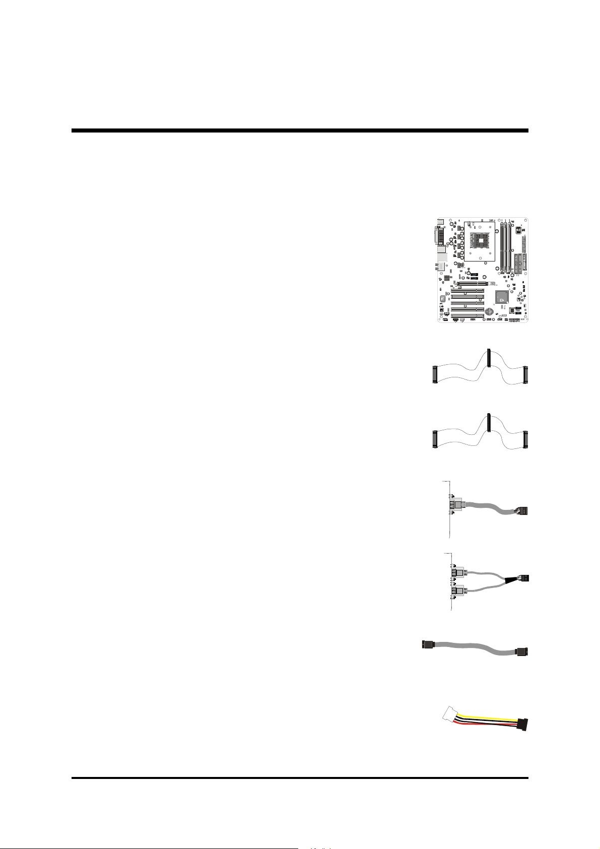
Check all items with your AN51R mainboard to make sure nothing is missing. A complete package should include:
- One Shuttle AN51R Mainboard
- One ATA 133/100/66 Ribbon Cable
- One Floppy Ribbon Cable
KB 1
USB 2
LAN 1
PCI1
JP21
1
1
ALC650
3A289T1 344F
CN6
JP 15
1
1
1394
FAN1
1
SATA3
SATA4
1
JP 11
1
1
Front Audio
TAIWANS
FB3741.1 0332A6
150
FORCE
n
VIDI
F
207GFSA
223503101
W49V002AP
W
1
JP 7
1
SW1SW2
1
-
+
+
-
PWON
GLED
PLED
JP 8
+
-
RST
HLED
- One piece of one port 1394 Cable
- One Twin-Port USB Cable
- One piece of Serial ATA Cable
- Two pieces of Serial ATA Power Cord
SERIAL
ATA
- 6 -
Page 14
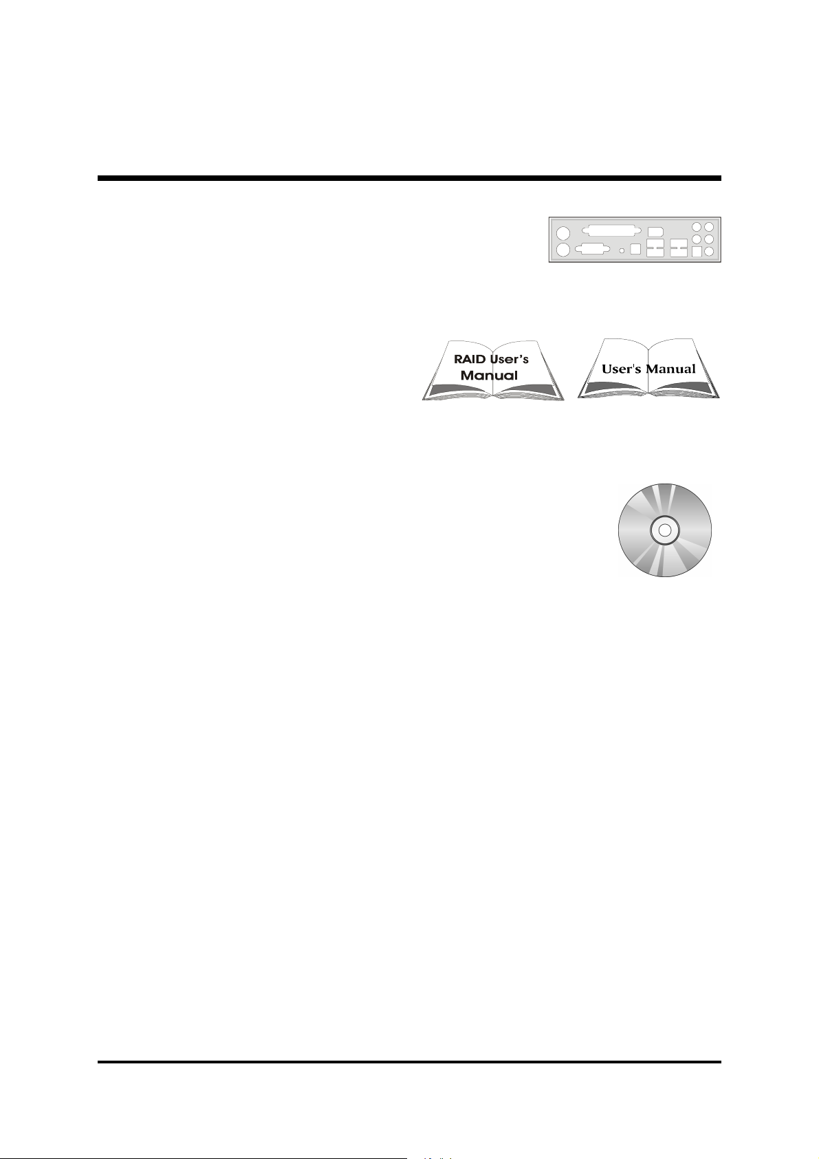
- I/O Shielding
- AN51R User's Manual
NVIDIA RAID User's Manual
- One Bundled CD-ROM, including:
Ø AN51R user's and nVIDIA raid manuals in PDF format
Ø DirectX9 Utility Driver
Ø nVIDIA Chipset Driver
Ø Broadcom Giga Lan Driver
Ø nVIDIA USB2.0 Driver
Ø Award Flashing Utility
- 7 -
Page 15

2 FEATURES
AN51R mainboard is dedicatedly designed for demanding PC users who desire high
performance and maximum intelligent features in a compact package.
2.1 Specifications
- CPU Support
AMD Athlon
- Chipset
nVIDIA nForce3 250 Single Chip for AMD Athlon64 CPU.
- Jumperless CPU Configuration
Soft-configuration FSB (The FSB speed is software configurable from 200MHz
to 280MHz in the Ratio/Voltage Control of BIOS setup program).
TM
64 on 754-pin SMT Socket.
- Integrated Serial-ATA (SATA) Interface
It compliants with SATA specification.
It supports dual channel SATA, 1.5 Gb/s per channel and power down
capabilities.
- External RSPI Serial-ATA PHY Interface (Marvell 3020)
It compliants with SATA specification.
It supports dual channel SATA, 1.5 Gb/s per channel and power down
capabilities.
- AC'97 Audio
Realtek ALC650 include SPDIF-IN function.
It compliants with AC97 2.2 specification.
5.1-Channel output but Line-in & Mic-in are shared with Rear-out & Center/
Bass that can be setting by device panel under OS.
Rear-out & Center/Bass have two set independent header which aren't
shared with any function.
It supports CD-IN/AUX-IN/Front Audio Panel/SPDIF-IN connectors & headers.
nForce 3 250 chipset build-in SPDIF-OUT that support pass-through function.
- Versatile Memory Support
Three 184-pin DIMM slots to support up to 3.2GB bandwidth for PC1600,
PC2100, PC2700, PC3200 compliant with DDR SDRAM module.
- 8 -
Page 16

System memory supports 64/128/256/512Mb technologies up to 3GB
capacity max and 1GB per DIMM.
- AGP Expansion Slot
Provides single 1.5V 8x AGP slot which supports 4X / 8X AGP devices.
- PCI Expansion Slots
It provides five PCI slots and supports 5788 Gigabit Lan (GbE)/VT6307 2
ports IEEE 1394 firewire on board.
- 8 USB 2.0/1.1 Interface Onboard
4X USB ports on back panel and two extended USB headers (4 ports) on front
panel.
- Gigabit Ethernet Controller (BCM5788KFB)
10/100/1000 Mbps operation rate. Support Wake-on-Lan (WOL) function.
- IEEE 1394 (VT6307)
Compliant with 1394 OHCI specification revision V1.0 and V1.1. Support
400Mb/s, 200Mb/s, 100Mb/s data transfer rate.
- I/O Interface
Provides a variety of I/O interfaces:
Ø 1 x PS/2 Mouse
Ø 1 x PS/2 Keyboard
Ø 1 x Serial port
Ø 1 x Parallel port
Ø 1 x Clear CMOS button
Ø 1 x SPDIF-In port
Ø 1 x 1394 port
Ø 4 x USB ports
Ø 1 x Gigabit Lan port
Ø 1 x Mic-In port
Ø 1 x Center /Bass Out port
Ø 1 x Line-In port
Ø 1 x Rear-Out port
Ø 1 x SPDIF-Out port
Ø 1 x Front-Out port
- 9 -
Page 17

- PCI Bus Master IDE Controller Onboard
Two Ultra DMA 133/100/66/33 bus master dual-channel IDE ports support up
to two IDE devices (one Master and one Slave per channel).
The IDE bus implentents data transfer speeds to 133/100/66/33 Mb / Sec and
also supports PIO mode 0, 1, 2, 3, 4.
80-pin cable backward compatible legacy ATAPI devices, ATAPI IDE CDROM, CD-R, CD-RW and LS-120 supports.
- ATX Power Supply Connector
ATX power supply unit can be connected to the onboard 20-pin ATX power
connector, and 4-pin ATX power connector. The unit supports Suspend and
Soft-On/Off modes by the dual-function power button.
- Advanced Configuration and Power Interface
Features four power-saving modes: S1 (Snoop), S3 (Suspend to RAM), S4
(Suspend to DISK), and S5 (Soft-Off). ACPI provides more efficient energysaving features controlled by your operating system that supports OS Direct
Power Management (OSPM) functionality.
- System BIOS
Provides licensed Award BIOS V6.0 PG on the 4Mb Flash ROM, and supports Green PC, Desktop Management Interface (DMI).
- Form Factor
System board conforms to the Full ATX specification.
Board dimension: 305 x 244 (mm).
- Advanced Features
Ø Low EMI - Built in spread spectrum. Unused PCI/SDRAM slots are shut off
by the automatic clock for reducing EMI.
Ø Dual Function Power Button - The system can be in any of the two
states: one is Suspend mode and the other is Soft-Off mode. Pushing the
power button for less than 4 seconds places the system into Suspend
mode. When the power button is pressed for longer than 4 seconds, the
system will enter Soft-Off mode.
Ø Modem Ring Power-On - The system can be powered on automatically
by the activation of modem ringing.
Ø CPU Multiplier Setting - This item allows users to adjust CPU Multiplier
in BIOS.
- 10 -
Page 18

Ø CPU/RAM/AGP Voltage Setting - These items allow users to adjust
CPU/RAM/AGP Voltage in BIOS.
- Intelligent Features
Ø Voltage Monitoring - Monitors various voltages of key elements, such as
the CPU, and other critical system voltage levels to ensure a stable current
passing through mainboard components.
Ø Fan Status Monitoring - To prevent the CPU from overheating, the CPU
fan is monitored by RPM, with which the cooling fan is required.
Ø Temperature Monitoring - This item allows users to make sure whether
the CPU or system runs under a suitable temperature.
- 11 -
Page 19
3 HARDWARE INSTALLATION
inbon
d
FAN21
SPEAKER
EPMI
PCI5
PCI4
PCI2
PCI3
1IRAGP1
JP 11
AUDIO 1
ATX
PWR
USB 5&6
SATA3
SATA4
SATA1
SATA2
A
3
n
T
M
USB 7&81JP 18
JP 19
88SR3020-TBCG615241.30304 AOPTaiwan
CN5
CN4
Floppy ConnectorTwo IDE ConnectorsSuper I/O & H/W Monitoring - IT 8712F-AATX Power Connector - ATX1
nVIDIA nForce3 250 Chipset
SPDIF-In Port
Front Panel Audio
Extended USB 5&6 and
7&8 Headers -JP7/JP20
Before removing/installing any of these devices: CPU, DIMMs, Add-On
Cards and Cables, please unplug the onboard power connector.
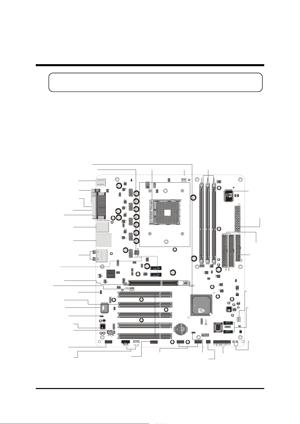
This section outlines how to install and configure your mainboard. Referring to the
following mainboard layout helps you identify various jumpers, connectors, slots
and ports.
3.1 Step-by-Step Installation
Accessories Of AN51R
ATX12V Power Connector - CN8
PS/2 Keyboard/Mouse
Port Connectors
Serial Port Connector
Parallel Port Connector
Clear CMOS Button
Connector
IEEE1394 Port /USB
Connectors
Giga LAN Port /USB
Connectors
Mic-In / Center-Bass
Line-In / Rear-Out
SPDIF-Out / Front-Out
Port Connectors
SATA 3 & 4
1.5V AGP Slot
FAN3
GIGA LAN Select-JP21
Five PCI Slots
VIA VT 6307
IEEE 1394 Chipset
1394 Select-JP22
Realtek ALC650
AUX_IN Connector
- CN6
Extended 1394a
Headers - JP 15
CD_IN Connectors
-CN4/CN5
KB 1
USB 2
LAN 1
PCI1
JP2 1
1
JP22
1
ALC650
3A289T1 344F
CN6
JP 15
1
1394
Header - JP 11
Socket 754
1
FAN1
FAN1
Three DIMM Slots
1
TAIWAN
S
FB3741.1 0332A6
150
FORCE
n
VIDI
FAN2
SATA 1 & 2
207GFSA
223503101
W49V002AP
JP 8
W
GLED+
PWON
+HLED-
1
JP 8
-
+
+
-
PWON
GLED
PLED
+
-
RST
HLED
Front Panel
Header - JP 19
+PLED-
SW1 SW2
Power Switc h - SW1/
Reset Switch - SW2
1
1
1
1
Front Audio
JP 7
1
Clear CMOS - JP18
IR Header - JP8
- 12 -
Page 20
Step 1
AMD CPU
Z
ADA3100AEP5AJAAAIC 0319PAWF358197 24002
5
Install the CPU
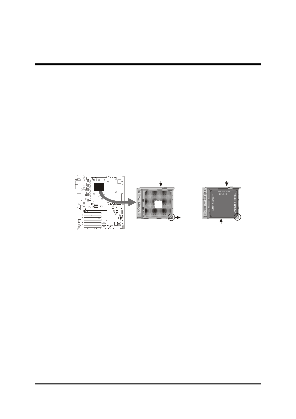
1. Locate the CPU ZIF (Zero Insertion Force) socket on the upper-right sector
of your mainboard (between the back panel connectors and the DIMM
memory slots).
2. Pull the CPU ZIF socket lever slightly sideways away from the socket to
unlock the lever, and then bring it to an upwardly vertical position.
3. Place your AMD Athlon TM 64 processor in the socket. Note that the CPU's
edges have been purposely designed non-symmetrically to prevent from in
serting the processor in the wrong direction. The following diagram demon
strates the correct placement of the CPU in the ZIF socket.
Lever
A Triangle
Mark
Lever
4. Slightly push the AMD Athlon TM 64 processor into the socket without apply
ing excessive force while making sure there is no gap between CPU and
socket. Then lower the socket-lever all the way down to its horizontal position and lock it to secure the CPU in place.
5. The AMD Athlon TM 64 processor requires a set of heatsink/fan to ensure
proper cooling of the processor. If heatsink/fan have not been already
mounted on your CPU, you must purchase the heatsink/fan separately and
have it in stalled. Plug the cable throught the heatsink/fan in the CPU fan
power connector located nearby. Note that there are several types of CPU
fan connectors. Normally, if your mainboard supports the hardware moni
toring function, a 3-pin fan power connector should allow your system to
detect the CPU fan's speed. The CPU fan can also run with a 2-pin fan power
connector, however, detection of CPU fan's speed is not supported. An
other type of CPU fan may feature a large 4-pin fan power connector, which
does not support CPU fan's speed detection and must be directly connected
to the system's power supply unit. Please refer to the following diagram.
- 13 -
Page 21
Step 2
Set Jumpers
The default jumper settings have been set for the common usage standard of
this mainboard. Therefore, you need not to reset the jumpers unless you require special adjustments as the following case:
Clear CMOS Setting
For first-time DIY system builders, we recommend that you not change the
default jumper settings if you are not quite familiar with the mainboard configuration procedures. The factory-set default settings are tuned for optimum
system performance. For advanced users who prefer to customize their system, section 3.2 Jumper Settings provides the detailed information on how
to configure your mainboard manually.
Step 3
Install DDR SDRAM System Memory
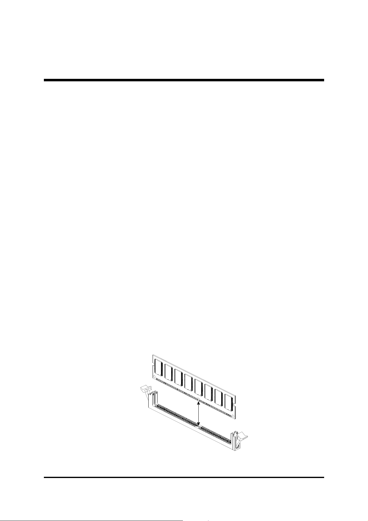
To install memory, insert DDR SDRAM memory module(s) in the DIMM
banks. Note that DDR SDRAM modules are directional and will not go in the
DIMM banks if they are not properly oriented. After the module is fully inserted into the DIMM bank, lift the clips of both sides of the DIMM bank to
lock the module in place.
DDR SDRAM
- 14 -
Page 22

Step 4
Install Internal Peripherals in System Case
Before you place the mainboard into your system case, we recommend that
you first assemble all the internal peripheral devices into the computer housing, including, but not limited to, the hard disk drive (IDE/HDD), floppy disk
drive (FDD), CD-ROM drive, and ATX power supply unit.
To install IDE & FDD drives, follow these procedures:
1. Set the required jumpers on each device according to the instructions provided by the manufacturer. (IDE, HDD, and CD-ROM have to set jumpers
to Master or Slave mode depending on whether you install more than one
device of each kind.)
2. Connect the IDE cable and FDD cable on the back panel of the internal
peripheral devices to the corresponding headers on board. Note that the
cable should be oriented with its colored stripe (usually red or magenta)
connected to pin#1 of the IDE or FDD connector on the mainboard and
on the device as well.
3. Connect an available power cable from your system power supply unit to
the back panel of each peripheral device. Note that the power cable is directional and cannot fit in if not properly positioned.
- 15 -
Page 23
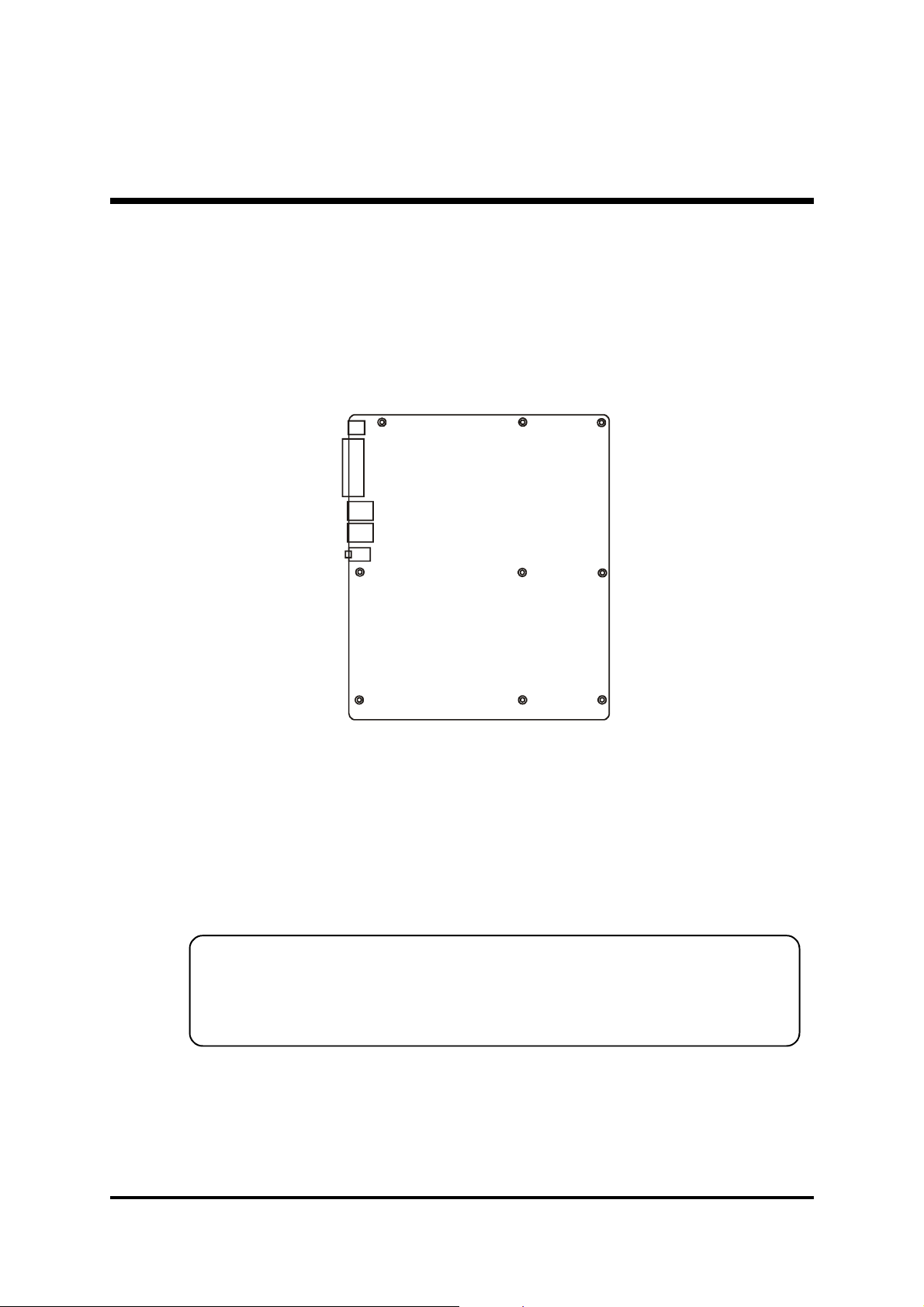
Step 5
Mount the Mainboard on the Computer Chassis
1. You may find there are a lot of mounting holes on your computer chassis
and mainboard. To match the holes on both properly, the key point is to
make the back panel of the mainboard in a close fit with your system case,
as shown below.
2. Position the studs between the chassis and the mainboard. The studs are
used to fix the mainboard and to keep a certain distance between them,
for avoiding any electrical shorts in-between.
(If your computer case is already equipped with mounting studs, you need
to tighten the screws to attach the mainboard.)
Note: In most computer housings, you can find 4 or more holes to place
studs for fixing the mainboard. If there aren't enough matching holes,
screw at least 4 studs to ensure the proper attachment of the mainboard.
- 16 -
Page 24
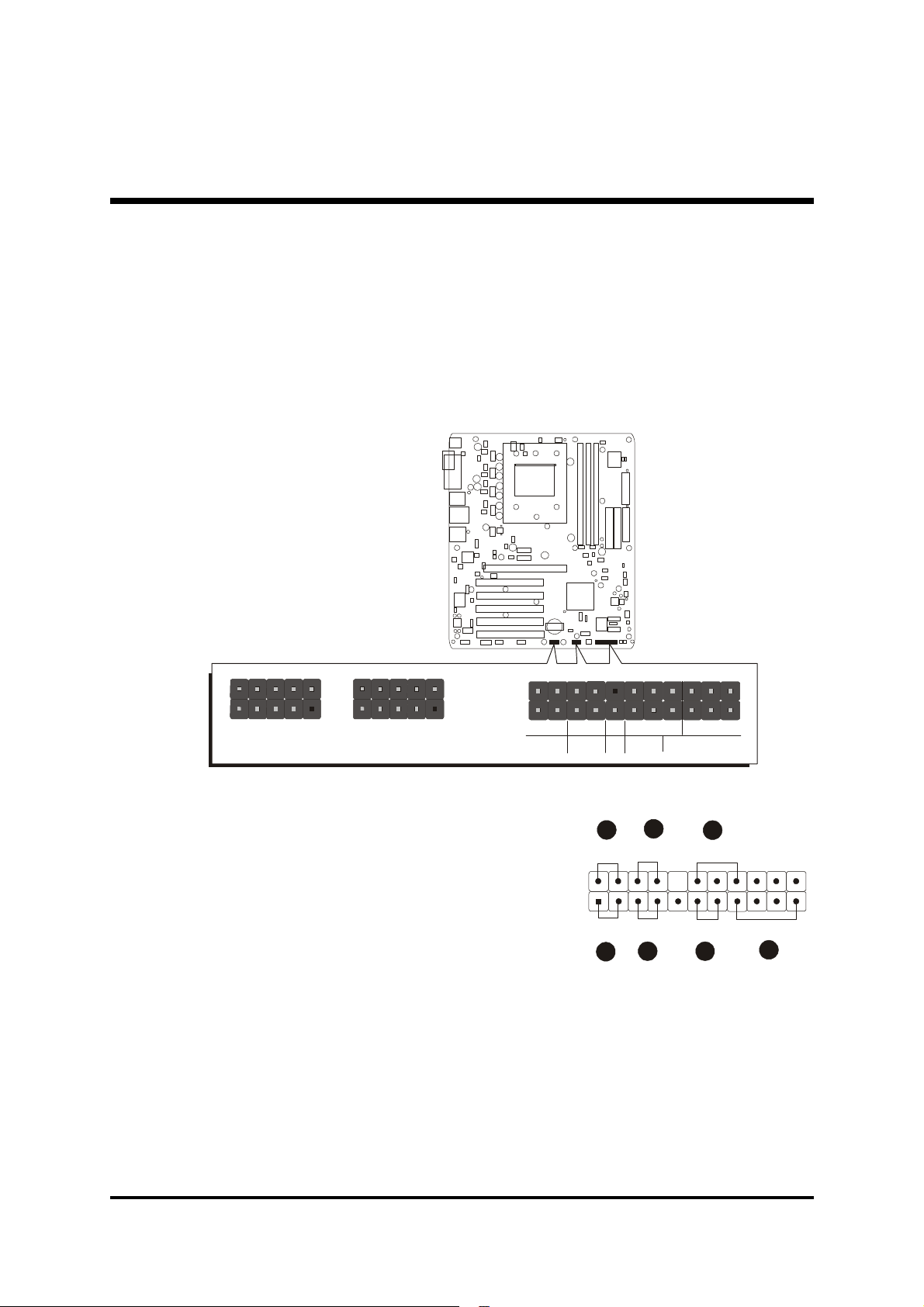
Step 6
SPEAKER
34567
SPEAKER
EPMI
PWON
GLED
HLED
PLED
Connect Front Panel LEDs/Switches/Speaker/USBs
You can find there are several cables existing in the system case and originating from the front panel devices (HDD LED, Green LED, Reset switch, PC
Speaker and USB devices etc.). These cables serve to connect the front-panel
LEDs, switches, speaker and USB connectors to the mainboard's front-panel
connectors group, as shown below.
JP 19
1
JP 7
USB 5&6
1
USB 7&8
1
-
+
+
-
RST
+
-
1. Green LED (GLED)
2. HDD LED (HLED)
3. ATX Soft Power On/Off (PWON)
4. Hardware Reset Switch (RST)
5. Power LED (PLED)
6. Hardware System Management
Interface (EPMI)
7. PC Speaker (SPEAKER)
8. Extended USB 5&6 and 7&8 Headers
- 17 -
JP 19
GLED
-
1
+
HLED
1
PLEDPWON
+
-
RST
2
+
EPMI
-
Page 25
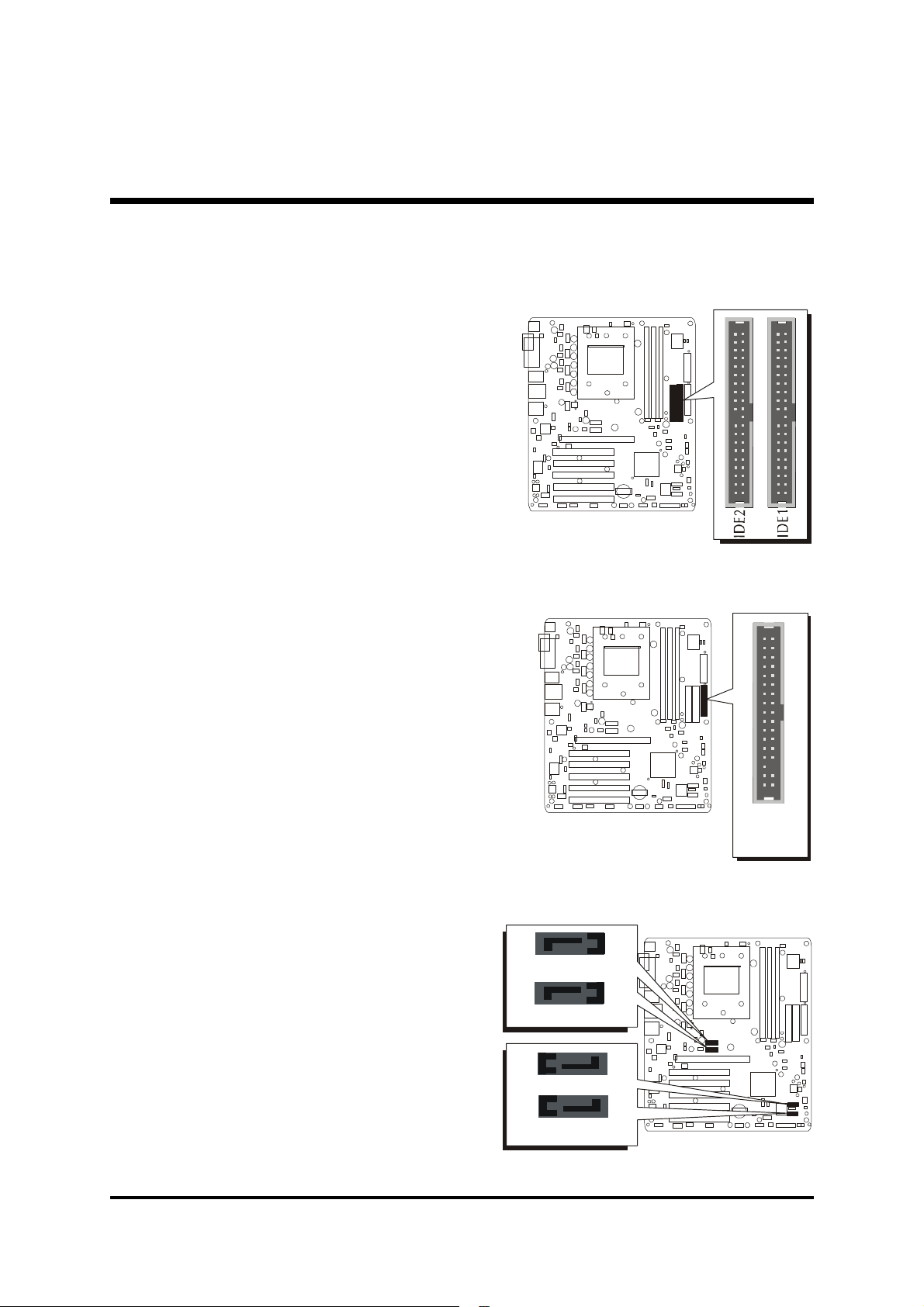
Step 7
1
1
1
P
1
1
Connect IDE and Floppy Disk Drives
1. IDE cable connectors
2. Floppy cable connector
FL
3.Serial ATA Connectors (SATA #1~4)
1
SATA3
1
SATA4
1
SATA2
1
SATA1
- 18 -
Page 26
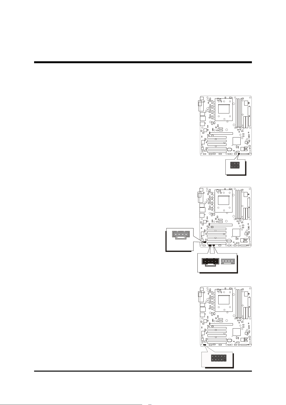
Step 8
JP8
CD_IN
CD_IN
1394
Connect Other Internal Peripherals
1. IR header (JP8)
2. Audio CD_IN connectors (CN4/CN5);
Audio AUX_IN connector (CN6)
1
IR
3. 1394 header (JP15)
1
CN6
AUX_IN
1
CN4
CN5
1
5
1
P
1
J
- 19 -
Page 27
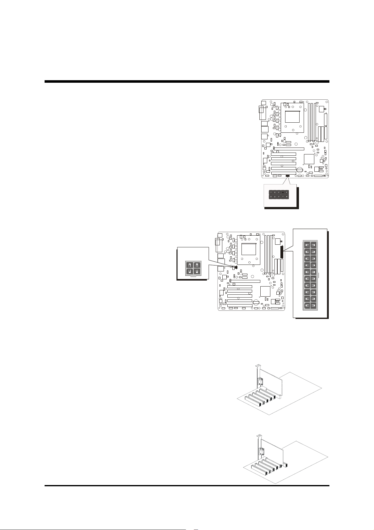
4. Front Panel Audio Header (JP11)
JP11
ATX1
Step 9
Connect the Power Supplies
1. System power connectors
1
Front Audio
(ATX1/CN8)
CN8
Step 10
Install Add-On Cards in Expansion Slots
1. Accelerated Grapics Port (AGP) Card
2. PCI Card
- 20 -
Page 28
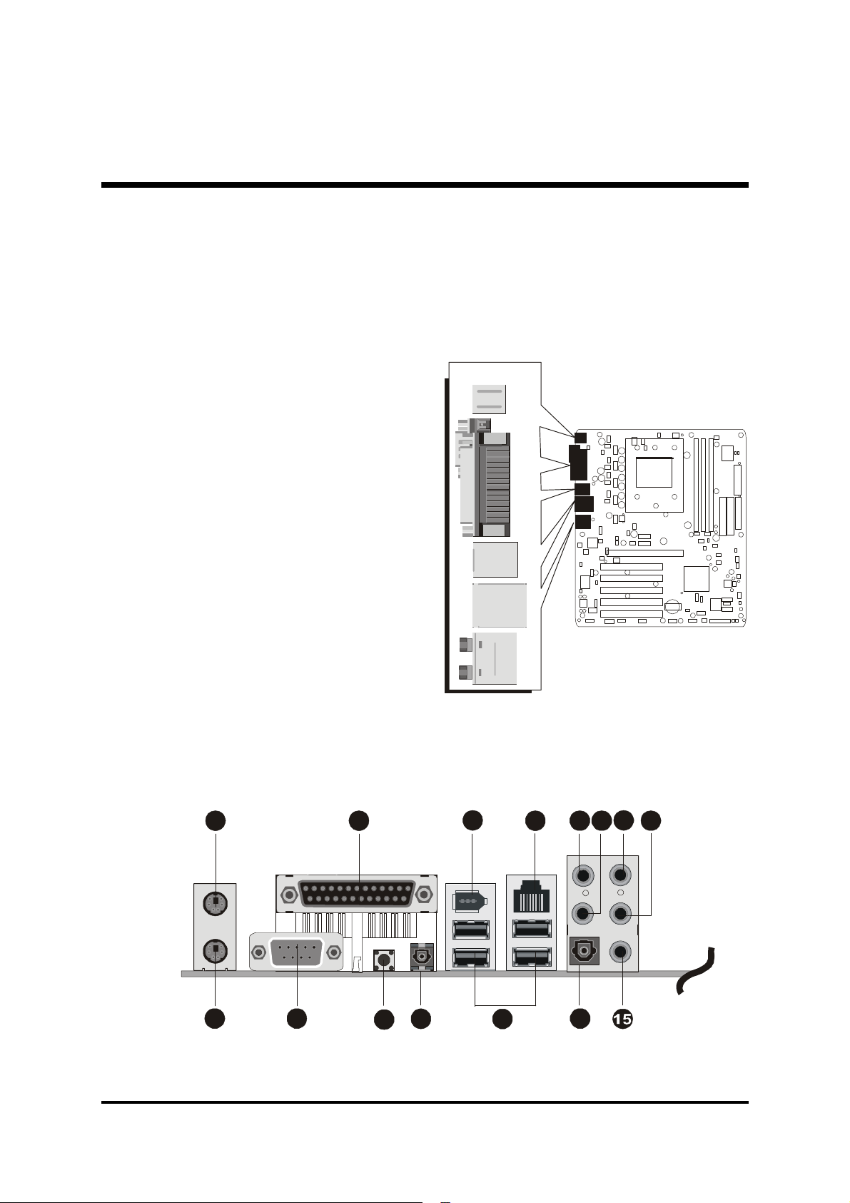
Step 11
789
12
14
Connect External Peripherals to Back Panel
You are now ready to connect the external peripherals to your system's back
panel.
1. PS/2 Mouse Port
2. PS/2 Keyboard Port
3. LPT1 Port
4. COM1 Port
5. Clear CMOS Button
6. SPDIF-In Port
7. 1394 Port
8. USB2.0 /1.1 Port #0~3
9. Gigabit Lan Port
10. 5.1-Channel Mic-in Port
11. 5.1-Channel Center/Bass Port
12. 5.1-Channel Line-In Port
13. 5.1-Channel Rear-Out Port
14. SPDIF-Out Port
15. 5.1-Channel Front-Out Port
1
2 6
4
3
5
12 13
10
11
- 21 -
Page 29

Step 12
System Boot Up For the First-Time
To ensure your system completedly and correctly installed, please refer to the
above installation steps once again before first booting up your system.
1. Insert a system-bootable floppy disk (DOS 6.2X, Windows 9X/NT, or
others), which contains the FDISK and FORMAT utilities.
2. Turn on the system power.
3. First, you need to use the FDISK utility to create a primary partition of the
hard disk. You can also add an extended partition if your primary partition
does not use all of the available hard disk space. If you choose to add an
extended partition, you will have to create one or more logical partitions
to occupy all the space available to the extended partition. The FDISK
utility will assign a drive letter (i.e. C:, D:, E:,......) to each partition shown in
the FDISK program. After the FDISK procedure, reboot your system by
using the same disk.
Note: DOS 6.2X and Windows 95A can only support up to 2.1GB of HDD
partition. If you use the FDISK utility with one of the operating systems mentioned above, you can only install your HDD into any partitions no larger than 2.1GB.
4. Now, use the FORMAT utility to format all the partitions you've created.
When formatting the primary partition (C:), key in the command, "FORMAT C:/S."
Note: FORMAT C:/S can transfer all the necessary boot system files into the
primary partition of your hard disk. Afterwards, your HDD will
become a bootable drive.
5. Install all the necessary drivers for CD-ROM, Mouse, etc.
6. Setup the complete operating system according to your OS installation
guide.
- 22 -
Page 30

Step 13
Install Drivers & Software Components
Please note that all the system utilities and drivers are designed for Win 9x/
2000/ME/NT/XP operating systems. Make sure your operating system is
already installed before running the installation programs on CD-ROM.
1. Insert the AN51R bundled CD-ROM into your CD-ROM drive. The auto-
run program will display the main installation window on screen.
2. Choose "Install Mainboard Software Driver."
3. Choose "Install DirectX9 Utility Driver" and complete it.
4. Choose "Install nVIDIA Chipset Driver" and complete it.
5. Choose "Install Broadcom Giga LAN Driver " and complete it.
6. Choose "Install nVIDIA USB2.0 Driver " and complete it.
7. Choose "Install AN51R user's/nVIDIA Raid Manual" and complete it.
8. Exit from the autorun drivers installation program.
- 23 -
Page 31
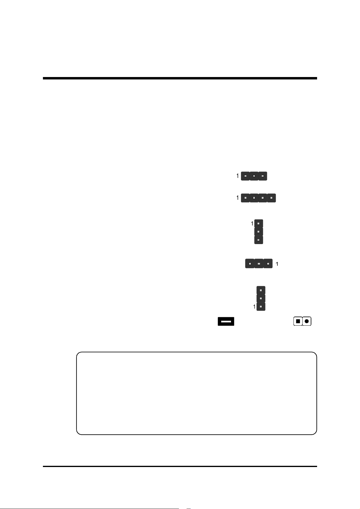
3.2 Jumper Settings
Several hardware settings are made through the use of mini jumpers to connect jumper pins on the mainboard. Pin #1 could be located at any corner of
jumpers, and the corner with a white right angle stands for Pin #1. There are
several types of Pin #1 as shown below:
3-pin and multi-pin (>3) jumpers shown as follows:
Pin #1 to the left:
Pin #1 on the top:
Pin #1 to the right:
Pin #1 on the bottom:
Jumpers with two pins capped are shown as for Close [On] or
for Open [Off]. To do this, please place a plastic mini cap on the desired pair
of pins.
Caution!
1. Do not remove the mainboard from its antistatic protective packaging
until you are ready to install it.
2. Carefully hold the mainboard by its edges and avoid touching its compo-
nents. When putting the mainboard down, place it on top of its original
packaging film, with the component side up.
3. Wear an antistatic wrist strap or take other suitable measures to prevent
electrostatic discharge (ESD) as handling this equipment.
- 24 -
Page 32
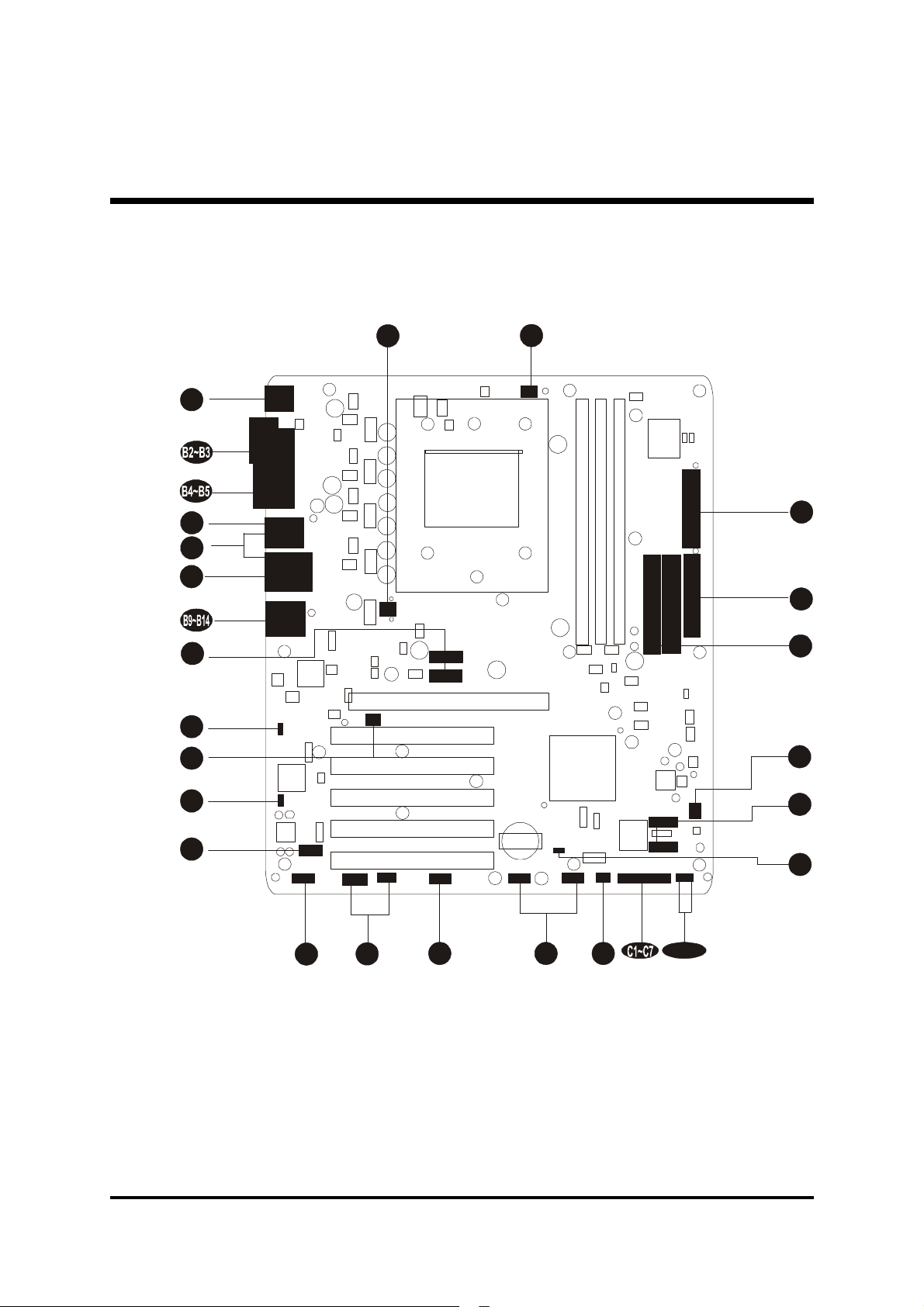
Jumpers & Connectors Guide
E6
E3E7E4
E8
E1D1D1E2A1
E9/E10
E2E2D2D2
Refer to the mainboard layout on page 12 and this section to help you identify jumpers, slots, and connectors along with their assigned functions.
B1
B6
B7
B8
A2
E2
E1
E2
A3
E5
CPU/Memory/Expansion Slots
Socket 754 : CPU socket for AMD Athlon TM 64 , 754-pins processor.
DIMM1/2/3 : Provides three DIMM slots for 64, 128, 256, 512 MB, and
supports up to 3GB capacity max and 1GB per DIMM.
(The total installed memory does not exceed 4GB.)
AGP : One AGP slot supports up to 8X AGP device.
PCI : Five 32-bit PCI expansion slots.
- 25 -
Page 33
Jumpers
A1
A2
A3
JP18 : Clear CMOS setting
JP21 : Giga LAN setting
JP22 : 1394 setting
Back Panel Connectors
B1
B1
B2
B3
B4
B5
B6
B7
B8
B9
B10
B11
B12
B13
B14
MS : PS/2 mouse port
KB : PS/2 keyboard port
LPT 1 : Parallel port
COM1 : Serial port
Clear CMOS : Clear CMOS button
SPDIF-In : SPDIF-In port
1394 : IEEE1394 Port
USB : USB ports 0/1/2/3
Lan Port : Gigabit Lan Port
MIC-In : Mic-In port
Center/Bass : Center/Bass port
Line-In : Line-In port
Rear-Out : Rear-Out port
SPDIF-Out : SPDIF-Out port
Front-Out : Front-Out port
Front Panel Connectors
C1
C2
C3
C4
C5
C6
C7
HLED : HDD LED
GLED : Green LED
RST : Hardware reset switch
PWON : ATX power on/off switch
EPMI : EPMI connector
PLED : Power LED
SPEAKER : Speaker connector
Internal-Peripheral Connectors
D1
D1
D1
D2
IDE1 : IDE primary interface (dual-channel)
IDE2 : IDE secondary interface (dual-channel)
FLP1 : Floppy disk drive interface
SATA1/2/3/4 : Serial ATA1/2/3/4 interface
- 26 -
Page 34

Other Connectors
E1
ATX1/CN8 : ATX power supply connectors
FAN1 : CPU fan connector
E2
FAN2/FAN3 : System fan connectors
E2
JP8 : IR header
E3
CN4/CN5 : Audio CD_IN connectors
E4
E5
CN6 : Audio AUX_IN connector
E6
JP7/JP20 : Extended USB header
E7
JP11 : Front-Panel Audio header
E8
JP15 : 1394 header
SW1 : PWRON button
E9
E10
SW2 : RESET button
- 27 -
Page 35
F Jumpers
JP18
A1
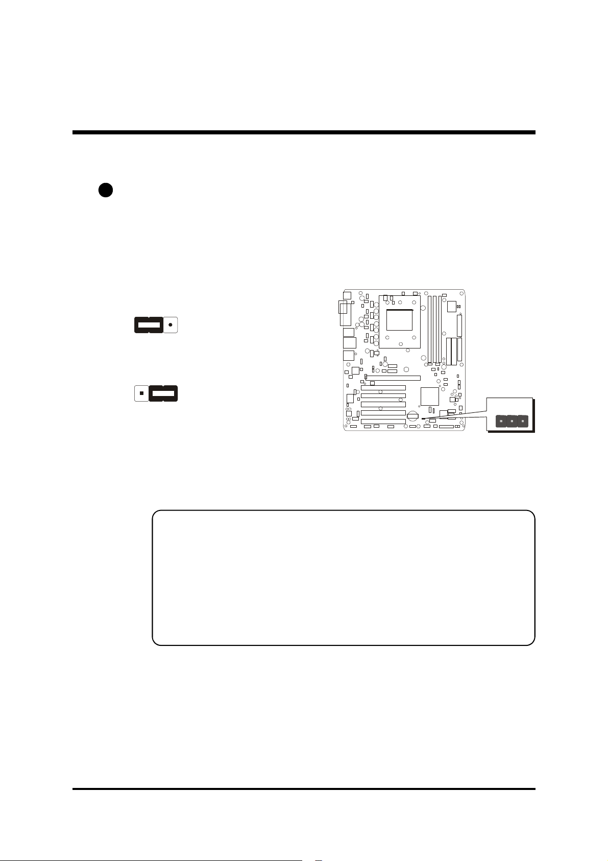
Clear CMOS Setting (JP18)
JP18 is used to clear CMOS data. Clearing CMOS will result in permanently
erasing previous system configuration settings and the original factory-set
system settings.
1
1
Pin 1-2 (Default)
Pin 2-3 (Clear CMOS)
1
Step 1. Turn off the system power (PC-->Off).
Step 2. Remove the ATX power cable from the ATX power connector.
Step 3. Remove the jumper cap from pins 1-2.
Step 4. Place the jumper cap on pins 2-3 for a few seconds.
Step 5. Restore the jumper cap to pins 1-2.
Step 6. Plug the ATX power cable into the ATX power connector.
Step 7. Turn on the system power (PC-->On).
- 28 -
Page 36
A2
1
1
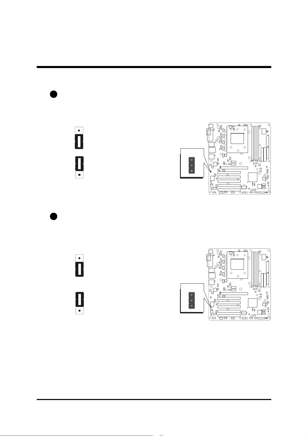
Giga LAN Setting (JP21)
JP21 is used to set Giga LAN.
Pin 1-2 Enable (Default)
JP21
Pin 2-3 Disable
1
A3
1394 Setting (JP22)
JP22 is used to set 1394.
Pin 1-2 Enable (Default)
Pin 2-3 Disable
1
1
JP22
1
- 29 -
Page 37
F Back Panel Connectors
B1
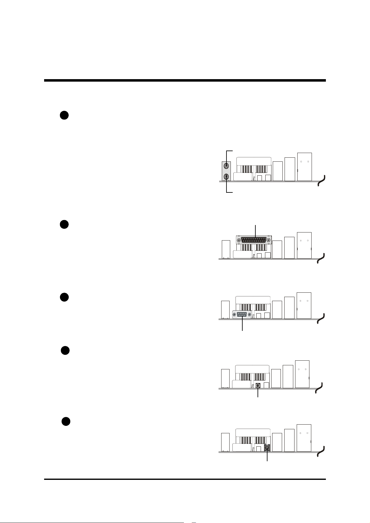
PS/2 Mouse & PS/2 Keyboard Port
Connectors
Two 6-pin female PS/2 Mouse & Keyboard
connectors are located on the rear panel of
the mainboard. In a desktop computer, the
PS/2 Mouse connector is situated on the top
of the PS/2 Keyboard connector. In a tower
computer, the PS/2 Mouse connector is located on the rightside of the PS/2 Keyboard
connector.
PS2 Mouse Port
PS2 Keyboard Port
B2
Parallel Port Connector
One DB25 female parallel connector is located on the rear panel of the mainboard.
Plug the cable from your parallel device
(printer, scanner, etc.) into this connector.
B3
COM1 Port Connector
Attach serial device cables to the DB9 serial ports COM1 at the back panel of your
computer.
B4
Clear CMOS Button
Please follow the steps as below:
Step 1. Turn off the system power (pc->
off).
Step 2. Remove ATX Power cable from
ATX Power connector.
Step 3. Push the button for a few seconds.
Parallel Port
COM1 Port
Clear CMOS Button
B5
SPDIF-In Port Connector
SPDIF-In connector can convey digital audio data from optic fiber.
SPDIF-In Port
- 30 -
Page 38
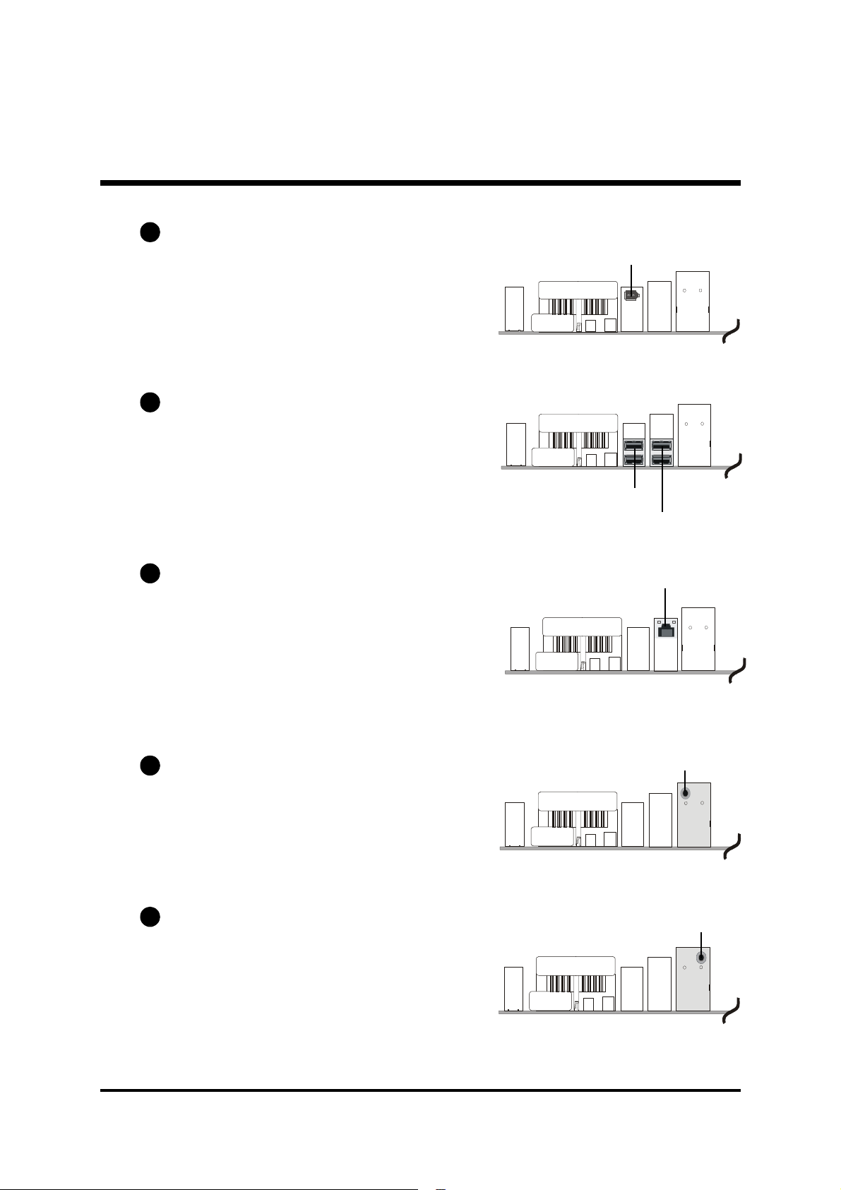
B6
IEEE 1394 Port Connector
This mainboard offers one 1394 port on
back-panel. Plug device jack into an available 1394 connector.
B7
USB Port Connectors
This mainboard offers 4 USB ports on back
panel. Plug each USB device jack into an
available USB0~USB3 connector.
B8
Gigabit LAN Port Connector
This mainboard can accommodate one
device on LAN. Attach a LAN cable to the
LAN port at the back-panel of your computer.
IEEE 1394 Port
USB Port 0/1
USB Port 2/3
Gigabit LAN Port
B9
Mic-In Port Connector
Mic-In is a 1/8-inch jack that provides a
mono input. It can use a dynamic mono
or stereo microphone with a resistance of
not more than 600 Ohms.
B10
Center/Bass Out Port Connector
Center/Bass is a stereo output port through
which the combined signal of all internal
and external audio sources on the board
is output. It can be connected to 1/8-inch
TRS stereo headphones or to bass/center
amplified speakers.
- 31 -
Mic-InPort
Center/Bass Out Port
Page 39
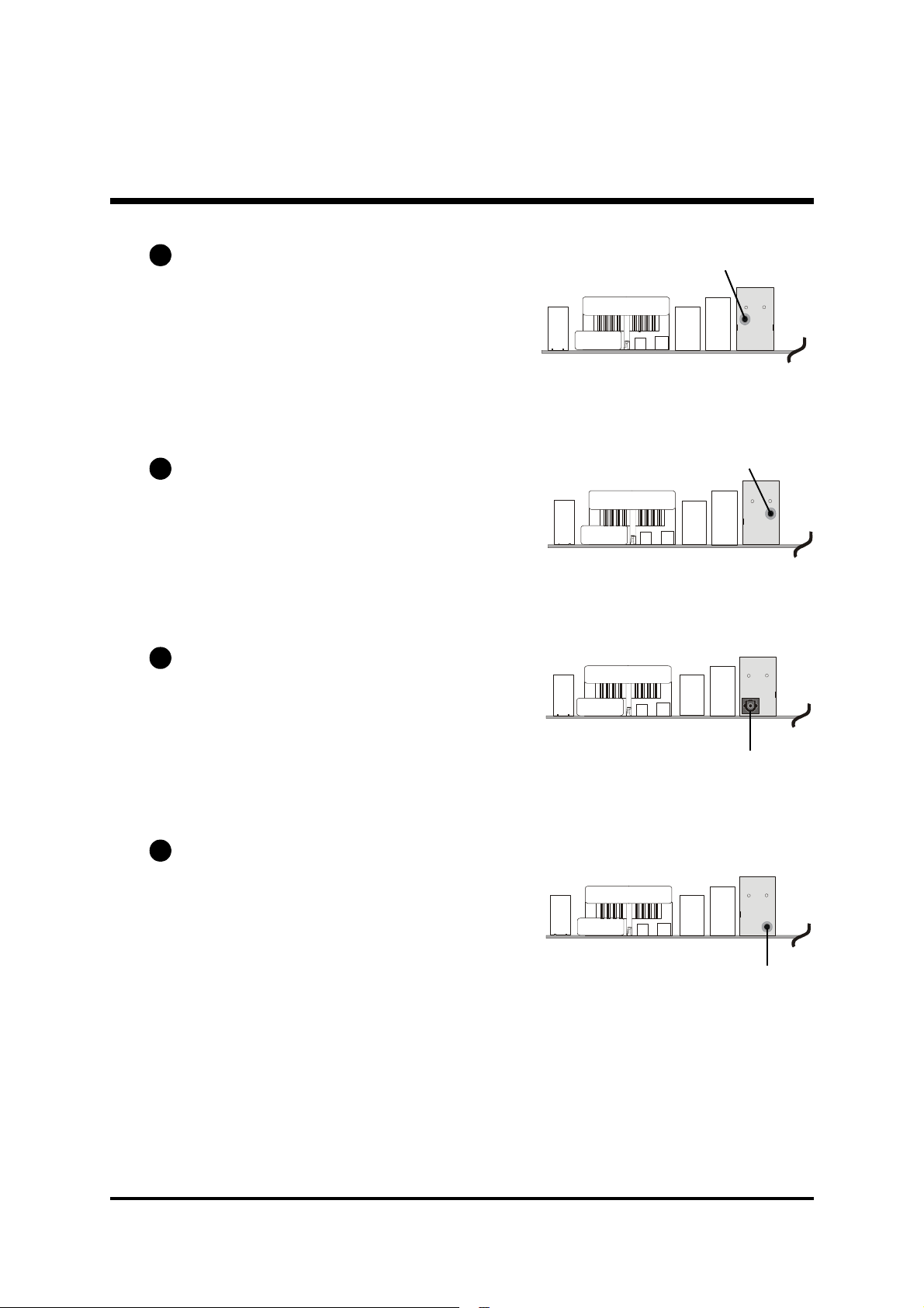
B11
Line-In Port Connector
Line-In is a stereo line-level input port that
accepts a 1/8-inch TRS stereo plug. It can
be used as a source for digital sound recording, and a source to be mixed with
the output, or both.
Line-In Port
B12
Rear-Out Port Connector
Rear-Out is a stereo line-level input port
that accepts a 1/8-inch TRS stereo plug. It
can be used as a source for digital sound
recording, and a source to be mixed with
the output, or both.
B13
SPDIF-Out Port Connector
SPDIF-Out connector can convey digital
audio data to digital decoder.
B14
Front-Out Port Connector
Front-Out is a stereo output port through
which the combined signal of all internal
and external audio sources on the board
is output. It can be connected to 1/8-inch
TRS stereo headphones or to amplified
speakers.
Rear-Out Port
SPDIF-Out Port
Front-Out Port
- 32 -
Page 40
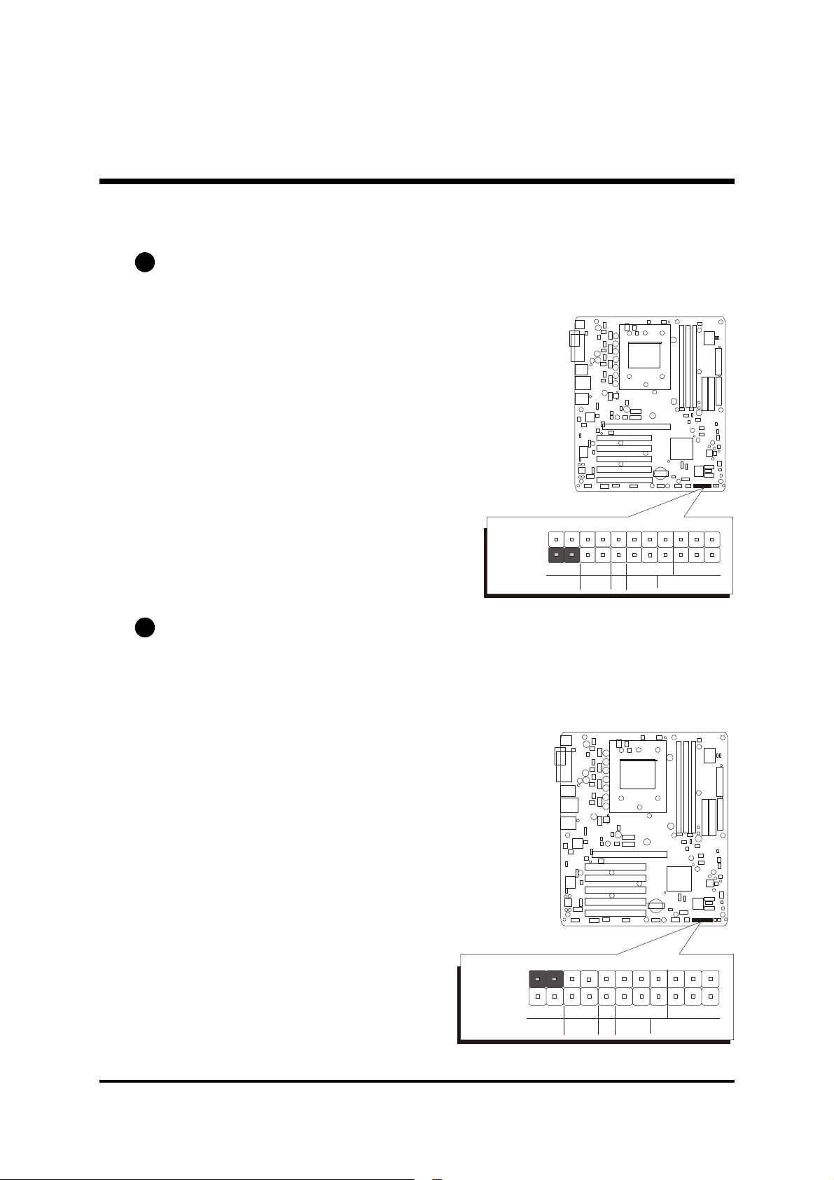
F Front Panel Connectors
SPEAKER
EPMI
PWON
GLED
HLED
PLED
SPEAKER
EPMI
PWON
GLED
HLED
PLED
HDD LED Connector (HLED)
C1
Attach a connector cable from the IDE device LED to the 2-pin (HLED) header.
The HDD LED lights up whenever an IDE device is active.
Pin Assignments:
1= HDD LED+
3= HDD LED-
C2
Green LED Connector (GLED)
JP 19
1
-
+
+
-
RST
+
-
The Green LED (GLED) indicates that the system is currently in one of the power
saving modes (Doze/Standby/Suspend). When the system resumes to the normal operation mode, the Green LED will go off. Attach a 2-pin Green LED cable
to the (GLED) header.
Pin Assignments:
2= GRLED4= GRLED+
JP 19
1
-
+
+
-
RST
+
-
- 33 -
Page 41
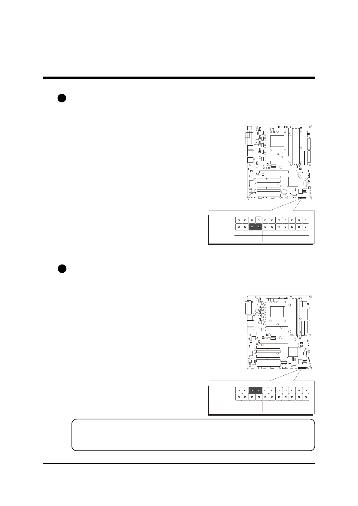
C3
SPEAKER
EPMI
PWON
GLED
HLED
PLED
SPEAKER
EPMI
PWON
GLED
HLED
PLED
Hardware Reset Connector (RST)
Attach a cable to the 2-pin (RST) header. Pressing the reset switch causes the
system to restart.
Pin Assignments:
5= Reset button
7= Ground
JP 19
C4
ATX Power On/Off Switch Connector (PWON)
1
-
+
+
-
RST
+
-
The Power On/Off Switch is a momentary type switch used for turning on or off
the ATX power supply. Attach a connector cable to the 2-pin (PWON) header
on the mainboard.
Pin Assignments:
6= Power-on button
8= Ground
JP 19
1
-
+
+
-
Note : Please notice all the LED connectors are directional. If your
chassis's LED does not light up during running, please change it
to the opposite direction.
RST
+
-
- 34 -
Page 42
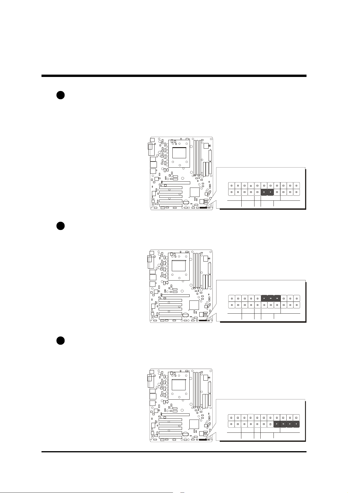
C5
SPEAKER
EPMI
PWON
PLED
SPEAKER
EPMI
PWON
PLED
SPEAKER
EPMI
PWON
PLED
EPMI Connector (EPMI)
A Hardware System Management Interface (EPMI) header may be attached to a
2-pin momentary switch. Press the switch to force the system into a power saving mode; press it again to resume it to a normal operation situation.
Pin Assignments:
11= EXT-SMI
13= Ground
C6
Power LED Connector (PLED)
Attach a 3-pin Power LED connector cable to the (PLED) header. The power
LED stays light while the system is on.
Pin Assignments:
12= Power LED+
14= NC
16= Ground
1
-
+
1
-
+
JP 19
GLED
HLED
JP 19
GLED
HLED
+
-
+
-
RST
RST
+
-
+
-
C7
Speaker Connector (SPEAKER)
Attach a PC speaker cable to the 4-pin speaker connector (Speaker).
Pin Assignments:
15= Speaker out
17= NC
19= NC
21= VCC(5VSB)
- 35 -
1
+
JP 19
-
GLED
HLED
+
-
RST
+
-
Page 43
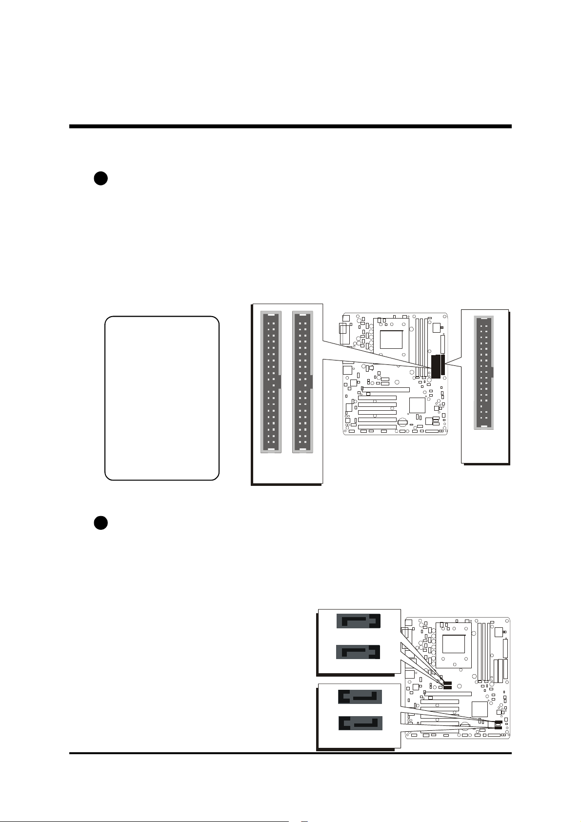
F Internal Peripherals Connectors
FLP
1
1
D1
Enhanced IDE, Floppy Connectors
The mainboard features two 40-pin dual-channel IDE device connectors
(IDE1/IDE2) providing support for up to four IDE devices, such as CD-ROM
and Hard Disk Drives (H.D.D.).
This mainboard also includes one 34-pin floppy disk controller (FDC) to
accommodate the Floppy Disk Drive (FDD). Moreover, this mainboard
comes with one 80-pin ATA 100/66/33 ribbon cable to connect to IDE
H.D.D. and one 34-pin ribbon cable for F.D.D. connection.
Important:
Ribbon cables are
directional, therefore, make sure to
always connect
with the red cable
stripe on the same
side as pin #1 of
the IDE1/IDE2 or
FDC connector on
the mainboard.
1 1
IDE2
IDE1
D2
Serial ATA Connectors
The Serial ATA is an envolutionary replacement for the Parallel ATA physical storge interface. Serial ATA is scalable and will allow future enhancements to the computing platform. The Serial ATA supports all ATA and
ATAPI device, including CDs, DVDs, tapes devices, high capacity removable devices, zip drivers, and CDRW's. The Serial ATA interface supports
data transfer rates up to 150MB/s.
1
SATA3
1
SATA4
1
SATA2
1
SATA1
- 36 -
Page 44
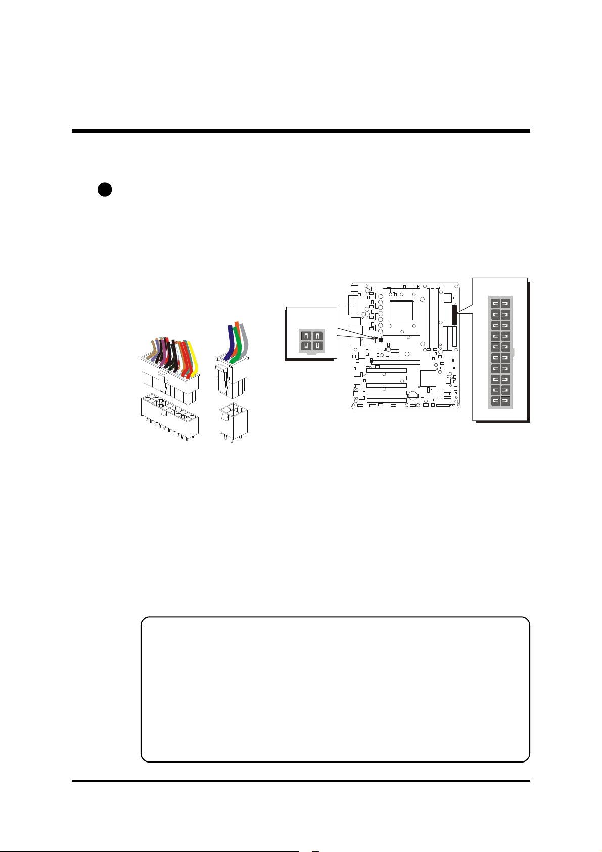
F Other Connectors
ATX1
E1
ATX Power Supply Connectors (ATX1/CN8)
This motherboard uses 20-pin ATX power header (ATX1), and comes with
the other one header (CN8). Please make sure you plug each in the right
direction. It is essential to have these two power supply connectors plugged
or your system won't boot up.
ATX1
A traditional ATX system remains in the power-off stage when AC power resumes from power failure. However, it is inconvenient for a network server or
workstation if there is not an UPS to execute power-on. Thus, this motherboard
supports an AC Power Auto Recovery function to solve this problem. You may
enable the function, "PWRON After PWR-Fail," in the sub-menu of "Power
Management Setup" within the BIOS setup program.
CN8
CN8
Note 1: The ATX power connector is directional and will not go in
unless the guides match perfectly, making sure that pin#1 is
properly positioned.
Note 2: Make sure the latch of the ATX power connector clicks into
place to ensure a solid attachment.
Note 3: Your ATX power supply must be supplied to ACPI+5V stand-
by power and at least 720mA compatible.
Note 4: Make sure your power supply have enough power for higher
speed processor installed.
- 37 -
Page 45
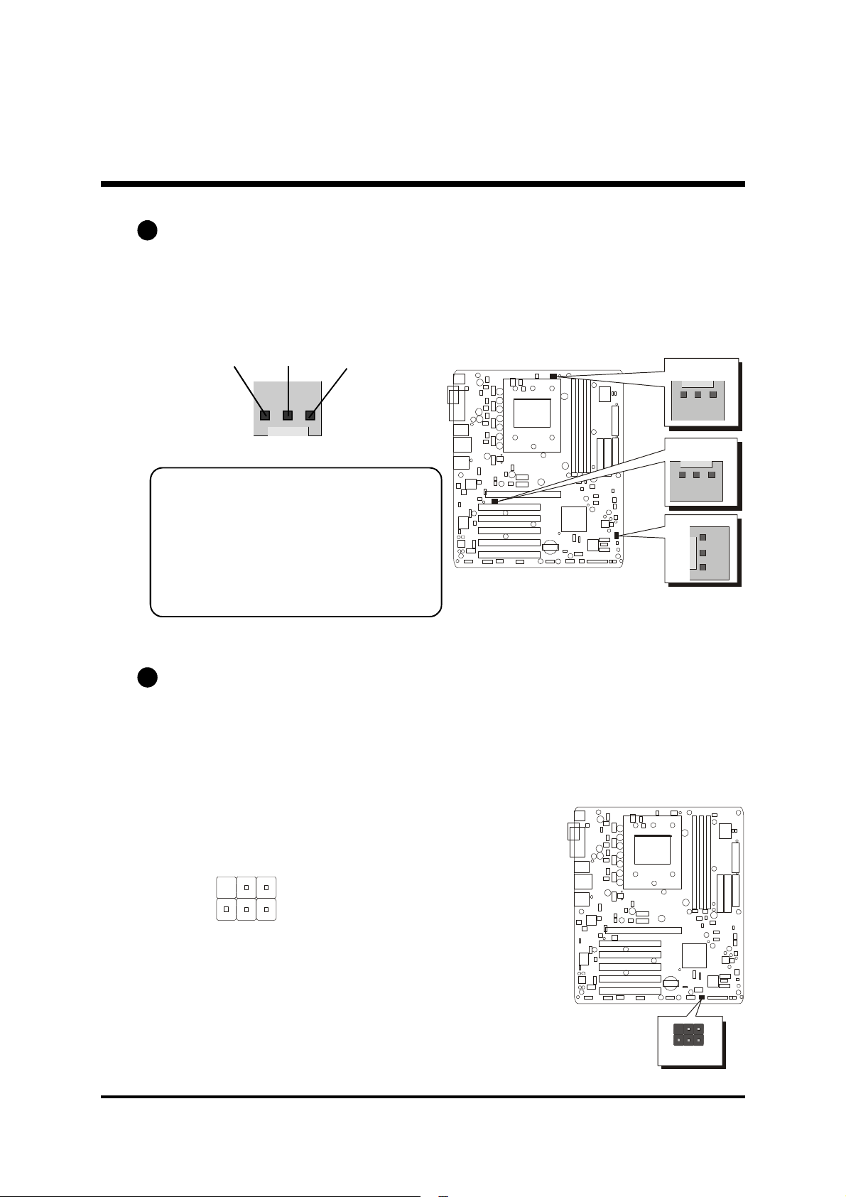
E2
JP8
1
3
5
FAN21
FAN3
JP8
CPU and System Fan Connectors (FAN1/2/3)
The mainboard provides three onboard 12V cooling fan power connectors
to support the CPU (FAN1) and the system (FAN2 / FAN3) cooling fans.
GND +12V
SENSE
1
Note: Both cable wiring and type of
plug may vary, which depend on the
fan maker. Keep in mind that the red
wire should always be connected to
the +12V header and the black wire
to the ground (GND) header.
E3
IR Header (JP8)
If you have an infrared device, this mainboard can implement IR transfer
function. This mainboard supports Normal, IrDA, ASKIR, or SCR transfer
modes. To enable this function, attach a 6-pin infrared device cable to the IR
header (JP8). Please note that every pin is properly allocated. If not, your IR
device may be damaged.
FAN1
1
1
4 6
2
1
Pin Assignments:
1=N/C 2=KEY
3=VCC 4=GND
5=IRTX 6=IRRX
- 38 -
1
IR
Page 46
E4
1
2
4
3
CN 4
1
124
3
CN 5
1
2
4
3
CN 6
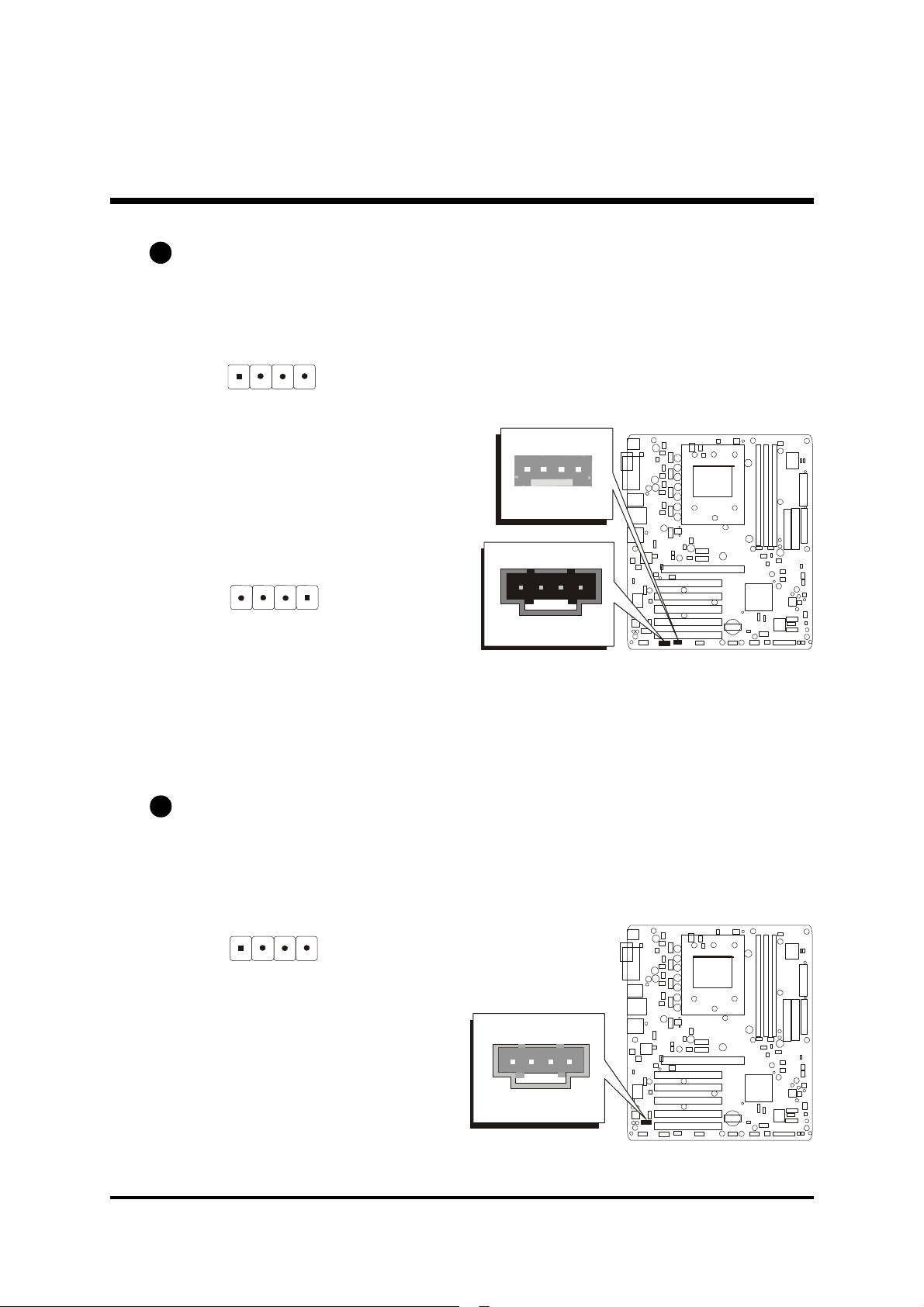
Audio CD_IN Connectors (CN4/CN5)
Ports CN4 (Black)/CN5 (White) can be used to connect stereo audio inputs
from CD-ROM, TV-tuner or MPEG card.
1
Pin Assignments:
1=CD In-Left
2=Ground
3=Ground
4=CD IN-Right
Pin Assignments:
1=Ground
2=CD-IN-Right
CN5
1
CD_IN
CN4
1
CD_IN
3=Ground
4=CD In-Left
E5
Audio AUX_IN Connector (CN6)
Port CN6 (White) can be used to connect a stereo audio input from CD-ROM,
TV-tuner or MPEG card.
1
Pin Assignments:
1=AUX-IN-Left
2=Ground
3=Ground
4=AUX-IN-Right
CN6
1
AUX_IN
- 39 -
Page 47
E6
1
13579
246810
USB 7&8
JP11
1
13579
246810
JP11
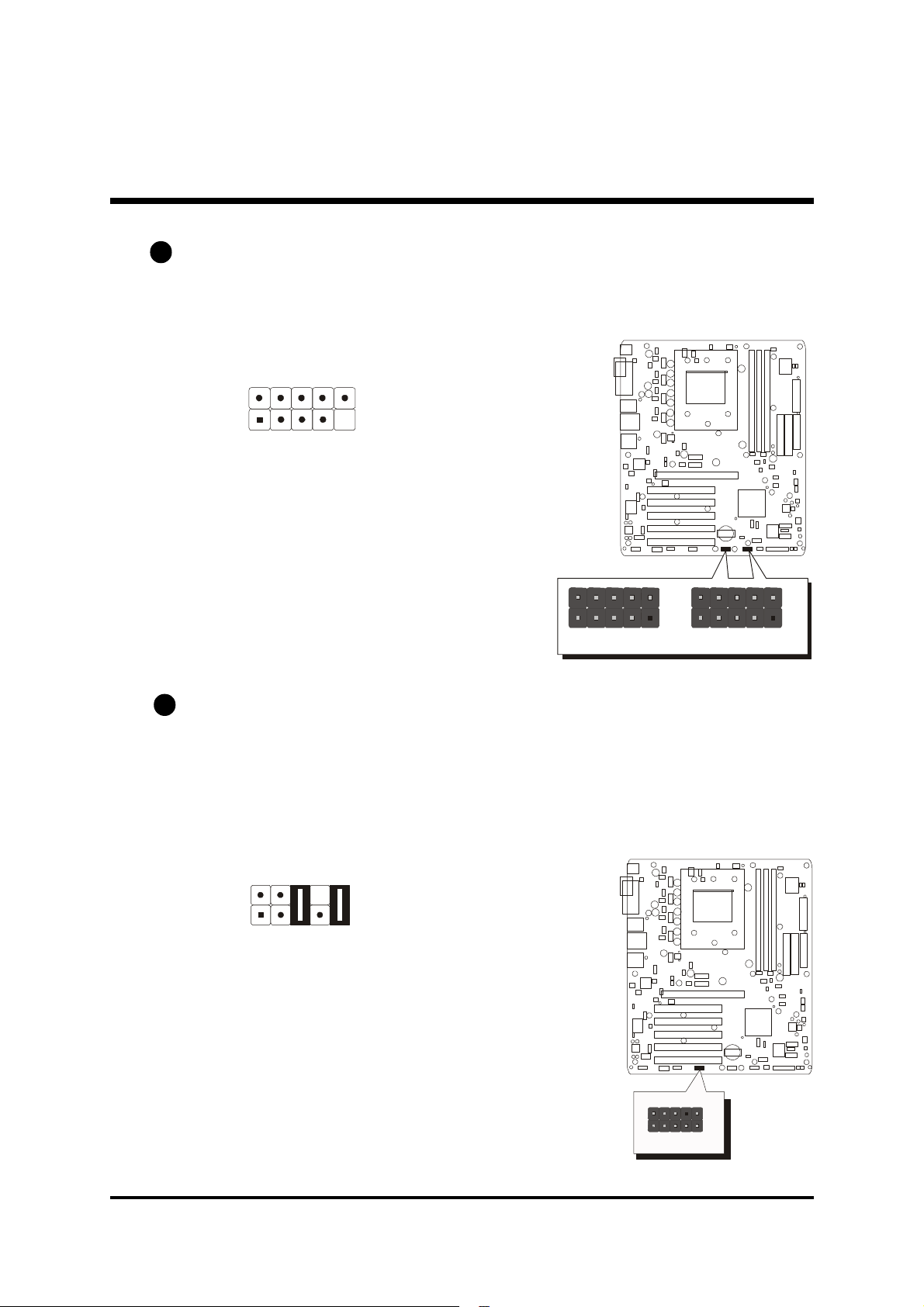
Extended USB Headers (JP7/JP20)
Headers JP7/JP20 (USB 5&6 and 7&8) are used to connect cables to USB
connectors mounted on front panel or back panel. The USB cable is optional
at the time of purchase.
JP 7
Pin Assignments:
1=VCC 2=VCC
3=Data0- 4=Data15=Data0+ 6=Data1+
7=Ground 8=Ground
9=KEY 10=N/C
E7
Front Panel Audio Header (JP11)
This header allows users to install an auxiliary Front-Oriented Audio port for
easier access. Either the Line-Out port connector on back panel or the front
panel Audio header is available at the same time. If you would like to use this
header on front panel, please remove all jumpers from it and install your special extra audio cable instead. Two mini jumpers must be setted on pins 5-6
and pins 9-10 when this header is not used.
Pin Assignments:
1=AUD_MIC 2=AUD_GND
3=AUD_MIC_VCC 4=RESERVE
5=AUD_FRONT_R 6=AUD_RET_R
1
JP 7
1
USB 5&6
7=HP_ON 8=KEY
9=AUD_FRONT_L 10=AUD_RET_L
- 40 -
1
Front Audio
Page 48
E8
1
23456
7
9
8
10
JP 15
1394
SW1
PWR ON
SW2
RESET
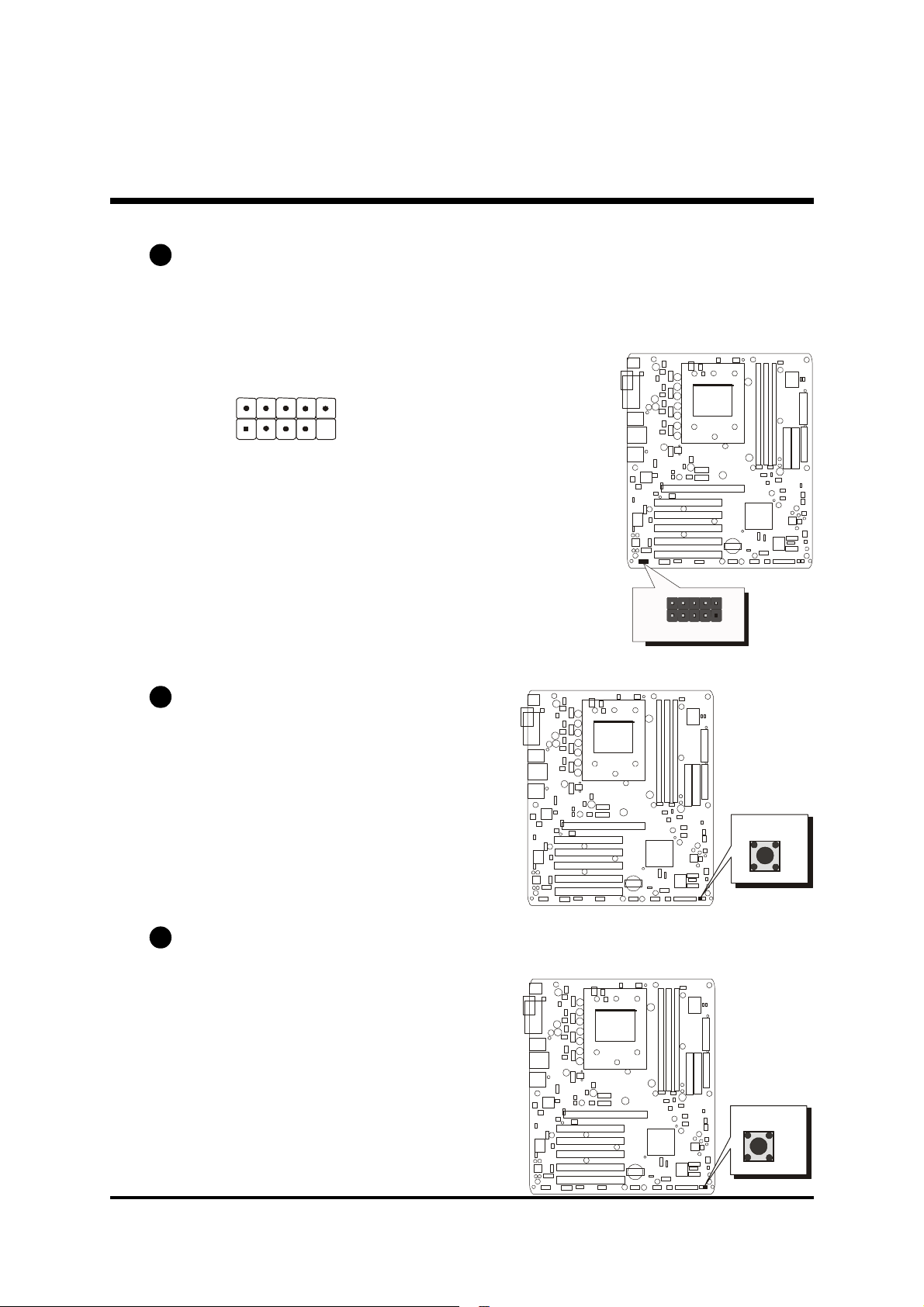
IEEE1394 Connector (JP15)
The header are used to connect the cable attached to 1394 connector which
are mounted on front panel or back panel. But the 1394 cable is optional at
the time of purchase.
1
Pin Assignments:
1=TPA+ 2=TPA3=GND 4=GND
5=TPB+ 6=TPB7=+12V(fused) 8=+12V(fused)
9=KEY 10=GND
E9
Power Button (SW1)
5
1
P
1
J
The Power On/Off Switch is a momentary
type switch used for turning on or off the
ATX power supply.
E10
Reset Button (SW2)
Pressing the reset switch causes the
system to restart.
- 41 -
Page 49

3.3 System Memory Configuration
The AN51R mainboard has three 184-pin DIMM slots that allow you to
install from 64MB up to 3GB of system memory. Each 184-pin DIMM (Dual
In-line Memory Module) slot can accommdate 64MB, 128MB, 256MB,
512MB, and 1GB compliant 2.5V/2.6V single or double side 64-bit wide
data path with or without ECC DDR-SDRAM modules. You do not need to
set any jumper to configure memory since the BIOS utility can detect the
system memory automatically. You can check the total system memory value
in the BIOS Standard CMOS Setup menu. As started previously, all DIMMs
must operate at the same frequency. The default frequency is the lowest of all
the DIMMs populated.
Note: The total installed memory does not exceed 3GB.
1. Memory Configurations:
Install memory in any or all of the banks. The combination shown as follows.
No.of dimms DIMM1
1 x8 single rank or x16 empty empty DDR 400
1 empty x8 single rank or x16 empty DDR 400
1 empty empty x8 single rank or x16 DDR 400
1 x8 duoble rank empty empty DDR 400
1 empty x8 duoble rank empty DDR 400
1 empty empty x8 duoble rank DDR 400
2 x8 single rank or x16 x8 single rank or x16 empty DDR 400
2 x8 single rank or x16 x8 duoble rank empty DDR 400
2 x8 single rank or x16 empty x8 single rank or x16 DDR 400
2 x8 single rank or x16 empty x8 duoble rank DDR 400
2 x8 duoble rank x8 single rank or x16 empty DDR 400
2 x8 duoble rank x8 duoble rank empty DDR 400
2 x8 duoble rank empty x8 single rank or x16 DDR 400
2 empty x8 single rank or x16 x8 single rank or x16 DDR 333
2 empty x8 single rank or x16 x8 duoble rank DDR 200
2 empty x8 duoble rank x8 single rank or x16 DDR 200
2 empty x8 duoble rank x8 duoble rank DDR 200
2 x8 duoble rank empty x8 duoble rank DDR 400
1,3
DIMM2
2,3
DIMM3
2
MAX
SPEED
- 42 -
Page 50

No.of dimms DIMM1
3 x8 single rank or x16 x8 single rank or x16 x8 single rank or x16 DDR 333
3 x8 single rank or x16 x8 single rank or x16 x8 duoble rank DDR 200
3 x8 single rank or x16 x8 duoble rank x8 single rank or x16 DDR 200
3 x8 single rank or x16 x8 duoble rank x8 duoble rank DDR 200
3 x8 duoble rank x8 single rank or x16 x8 single rank or x16 DDR 333
3 x8 duoble rank x8 single rank or x16 x8 duoble rank DDR 200
3 x8 duoble rank x8 duoble rank x8 single rank or x16 DDR 200
3 x8 duoble rank x8 duoble rank x8 duoble rank DDR 200
1,3
DIMM2
2,3
DIMM3
2. Upgrade Memory:
You can easily upgrade the system memory by inserting additional
DDR SDRAM modules in available DIMM banks. The total system
memory is calculated by simply adding up the memory in all DIMM
banks. After upgrade, the new system memory value will automatically
be computed and displayed in the field "Standard CMOS Setup" of
BIOS setup program.
2
MAX
SPEED
- 43 -
Page 51
4 SOFTWARE UTILITY
4.1 Mainboard CD Overview
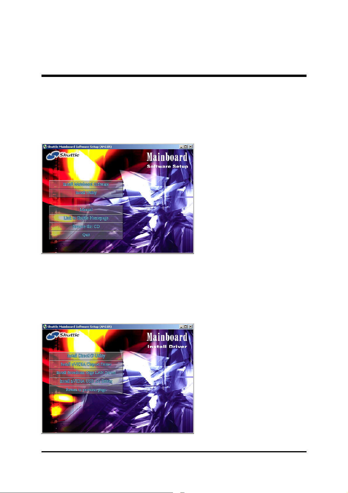
To start your mainboard CD disc, just insert it into your CD-ROM drive and
the CD AutoRun screen should appear. If the AutoRun screen does not
appear, double click or run D:\Autorun.exe (assuming that your CD-ROM
drive is drive D:)
Navigation Bar Description:
F Install Mainboard Software -
Installing DirectX9 Utility, nVIDIA
Chipset Driver, Broadcom Giga
LAN Driver and nVIDIA USB 2.0
Driver.
F Install Utility - Installing Acrobat
Reader and Winflash Utility.
F Manual - Installing Acrobat
Reader and AN51R user's manual
in PDF format.
F Link to Shuttle Homepage -
Link to shuttle website homepage.
F Browse this CD - Allows you to
see contents of this CD.
F Quit - Close this CD.
4.2 Install Mainboard Software
Select using your pointing device (e.g. mouse) on the "Install Mainboard
Software" bar to run into sub-menu.
The AN51R Software include:
[4.2.A] Install DirectX9 Utility Driver
[4.2.B] Install nVIDIA Chipset Driver
[4.2.C] Install Broadcom LAN Driver
[4.2.D] Install nVIDIA USB 2.0 Driver
- 44 -
Page 52
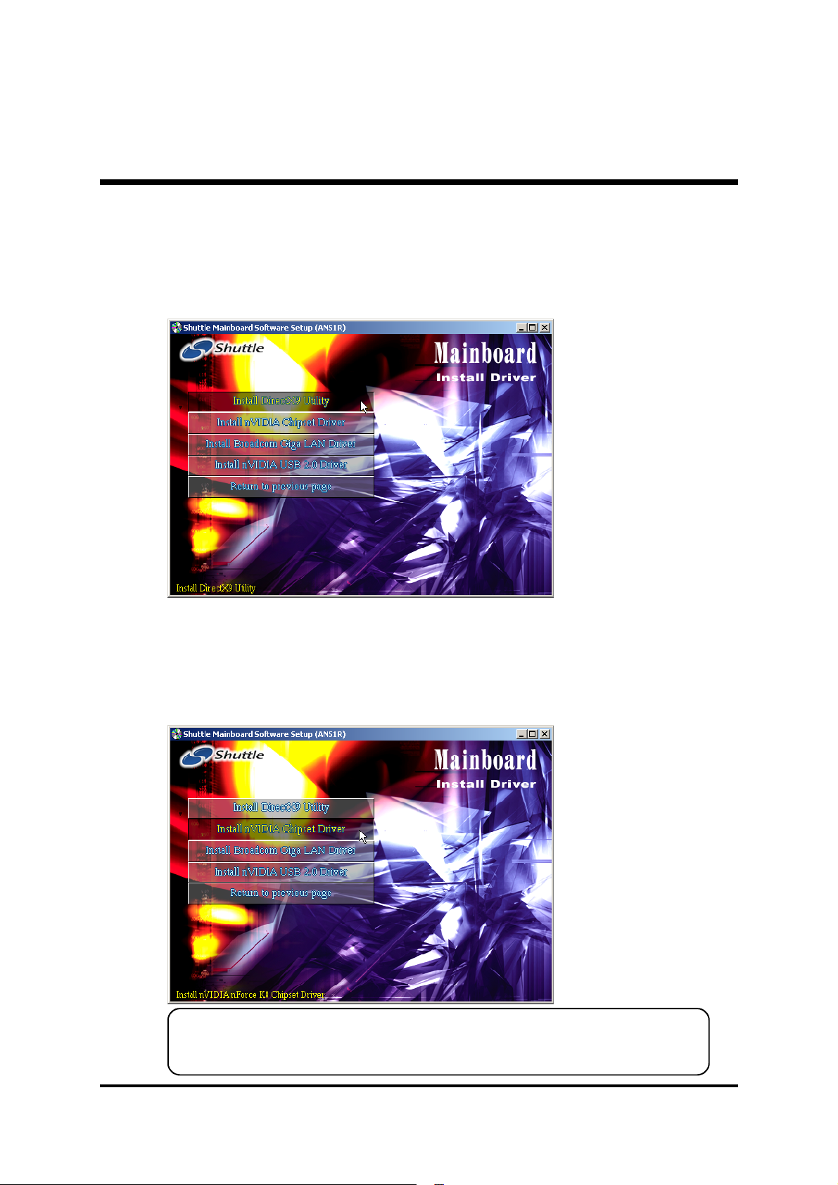
4.2.A Install DirectX9 Utility Driver
Select using your pointing device (e.g. mouse) on the "Install DirectX9
Utility Driver" bar to install DirectX9 Utility driver.
Once you made your selection, a Setup window
run the installation
automatically.
When the copying files
is done, make sure you
reboot the system to
take the installation
effect.
4.2.B Install nVIDIA Chipset System Driver
Select using your pointing device (e.g. mouse) on the "Install nVIDIA
Chipset Driver" bar to install chipset system driver.
Once you made your selection, a Setup window
run the installation
automatically.
When the copying files
is done, make sure you
reboot the system to
take the installation
effect.
Under Windows 98/ME, if the system doesn't have Serial-ATA harddisk,
please don't install this RAID Utility.
- 45 -
Page 53
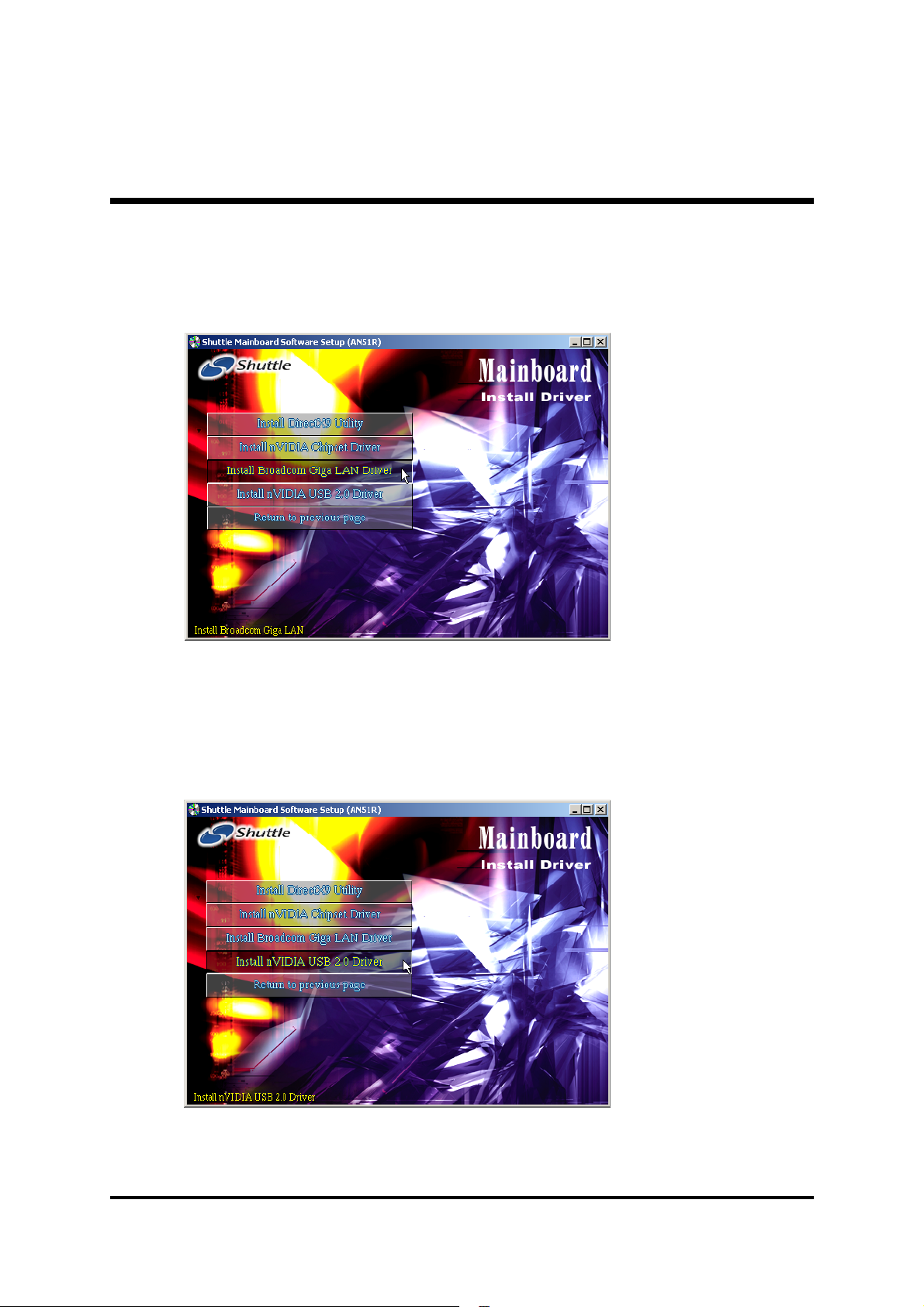
4.2.C Install Broadcom Giga LAN Driver
Select using your pointing device (e.g. mouse) on the " Install Broadcom
Giga LAN Driver" bar to install LAN driver .
Once you made your selection, a Setup window
run the installation
automatically.
When the copying files
is done, make sure you
reboot the system to
take the installation
effect.
4.2.D Install nVIDIA USB2.0 Driver
Select using your pointing device (e.g. mouse) on the "Install nVIDIA
USB2.0 Driver" bar to install USB2.0 driver.
Once you made your selection, a Setup window
run the installation
automatically.
When the copying files
is done, make sure you
reboot the system to
take the installation
effect.
- 46 -
Page 54
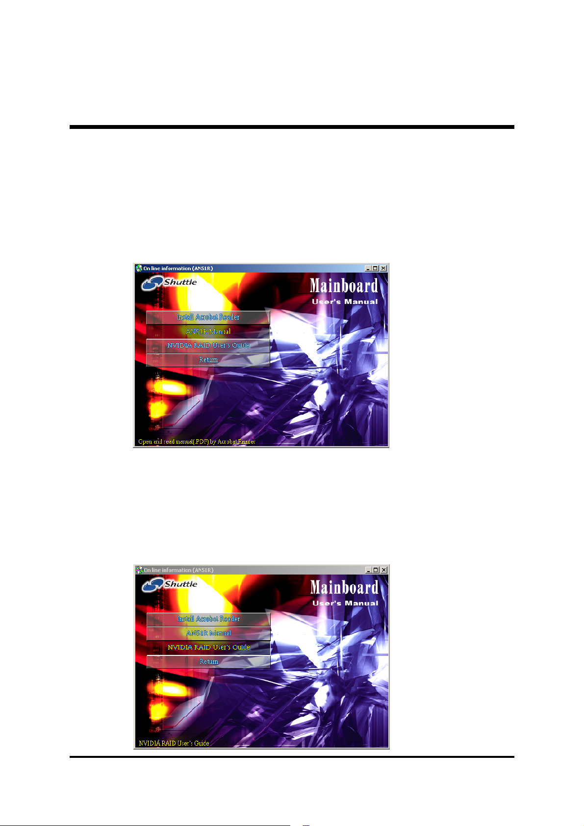
4.3A View the User's Manual
Insert the attached CD into your CD-ROM drive and the CD AutoRun screen
should appear. If the AutoRun screen does not appear, double click on
AutoRun icon in My Computer to bring up Shuttle Mainboard Software
Setup screen.
Select using your pointing device (e.g. mouse) on the "AN51R Manual"
bar.
Then Online Information windows will
appear on your screen.
Click on the "Install
Acrobe Reader" bar
if you need to install
acrobe reader.
Then click on
"AN51R Manual"
bar to view user's
manual.
4.3B View the NVIDIA RAID User's Guide
Insert the attached CD into your CD-ROM drive and the CD AutoRun screen
should appear. If the AutoRun screen does not appear, double click on
AutoRun icon in My Computer to bring up Shuttle Mainboard Software
Setup screen.
Select using your pointing device (e.g. mouse) on the "NVIDIA RAID
User's Guide" bar.
Then Online Information windows will
appear on your screen.
Click on the "Install
Acrobe Reader" bar
if you need to install
acrobe reader.
Then click on
"NVIDIA RAID
User's Guide" bar to
view user's manual.
- 47 -
Page 55

5 BIOS SETUP
AN51R BIOS ROM has a built-in Setup program that allows users to modify
the basic system configuration. This information is stored in battery-backed
RAM so that it retains the Setup information even if the system power is
turned off.
The system BIOS is managing and executing a variety of hardware related
functions in the system, including:
System date and time
Hardware execution sequence
Power management functions
Allocation of system resources
5.1 Enter BIOS
To enter the BIOS (Basic Input /Output System) utility, follow these steps:
Step 1. Power on the computer, and the system will perform its
POST (Power-On Self Test) routine checks.
Step 2. Press <Del> key immediately, or at the following message:
Press DEL to enter SETUP, or simultaneously press <Ctrl>,
<Alt>, <Esc> keys.
Note1. If you miss trains of words mentioned in step2 (the message
disappears before you can respond) and you still wish to enter BIOS Setup, restart the system and try again by turning the
computer OFF and ON again or by pressing the <RESET>
switch located at the computer front panel. You may also
reboot by simultaneously pressing the <Ctrl>, <Alt>,
<Del> keys.
Note2. If you do not press the keys in time and system does not
boot, the screen will prompt an error message, and you will
be given the following options:
"Press F1 to Continue, DEL to Enter Setup"
Step 3. As you enter the BIOS program, CMOS Setup Utility will
prompt you the Main Menu, as shown in the next section.
- 48 -
Page 56
5.2 The Main Menu
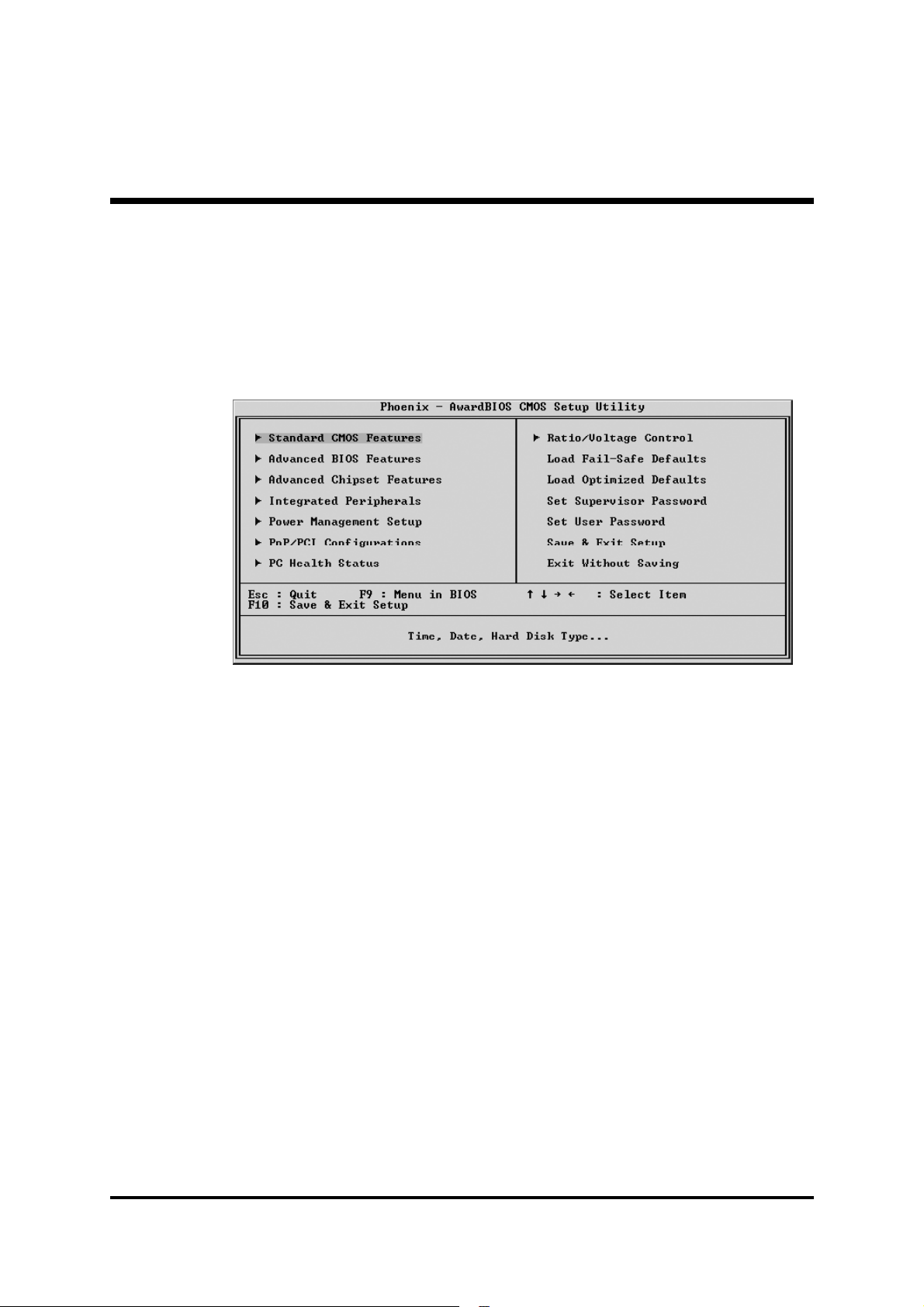
Once you enter the Award BIOS(tm) CMOS Setup Utility, the Main
Menu will appear on the screen. The Main Menu allows you to select
from several setup functions and two exit choices. Use the arrow keys
to select among the items and press <Enter> to accept and enter the
sub-menu.
Note that a brief description of each highlighted selection appears at the
bottom of the screen.
Setup Items
The main menu includes the following main setup categories. Recall
that some systems may not include all entries.
Standard CMOS Features
This menu displays the basic information about your system.
Advanced BIOS Features
Use this menu to set the advanced features available on your system.
Advanced Chipset Features
Use this menu to change the values in the chipset registers and optimize your system's performance.
Integrated Peripherals
Use this menu to specify your settings for integrated peripherals.
Power Management Setup
Use this menu to specify your settings for power management.
- 49 -
Page 57

PnP/PCI Configurations
This option configures how PnP (Plug and Play ) and PCI expansion
cards operate in your system.
PC Health Status
This entry shows the current system temperature, voltage, and fan
speed.
Ratio/Voltage Control
Use this menu to specify your settings for the ratio/voltage control.
Load Fail-Safe Defaults
Use this menu to install fail-safe defaults for all appropriate items in the
setup utility.
Load Optimized Defaults
Use this menu to install optimized defaults for all appropriate items in
the setup utility.
Set Supervisor Password
Use this menu to change, set, or disable supervisor/user password. It
allows you to limit access to the system and Setup, or only to Setup.
Save & Exit Setup
Save the changes that you have made in the Setup Utility and exit the
Setup Utility.
Exit Without Saving
Abandon all changes that you have made in the Setup Utility and exit
the Setup Utility.
- 50 -
Page 58
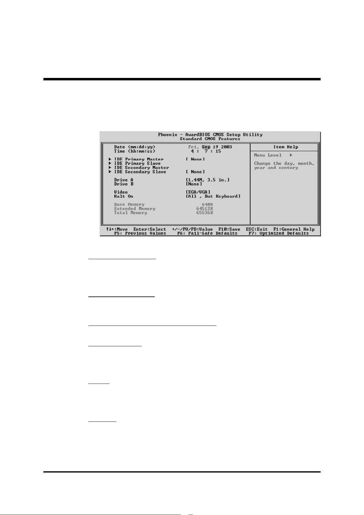
@ Standard CMOS Features
Use the arrow keys to highlight the item and then use the <PgUp> or
<PgDn> keys to select the value you want in each item.
Date (mm : dd : yy)
Set the system date. Note that if you are running a Windows OS, this
items are automatically updated whenever you make changes to the
Windows Date.
Time (hh : mm : ss)
Set the system time. The time is converted based on the 24-hour military-time clock. For example, 5:00:00 p.m. is 17:00:00.
IDE Primary/Secondary Master/Slave
Press <Enter> to enter the sub-menu of detailed options.
Drive A/DriveB
Select the type of floppy disk drive installed in your system.
Ø The choice: None, 360K, 5.25 in, 1.2M, 5.25 in, 720K, 3.5 in,
1.44M, 3.5 in, or 2.88M, 3.5 in.
Video
This item defines the video mode of the system. Leave this item at the
default value.
Ø The choice: EGA/VGA, CGA 40, CGA 80, or MONO.
Halt On
This item defines the operation of the system POST (Power-On Self Test)
routine. You can use this item to select which situation you want the
BIOS to stop the POST process and notify you.
Ø The choice: All Errors, No Errors, All, But Keyboard, All, But Diskette,
or All, But Disk/Key.
- 51 -
Page 59

Base Memory/Extended Memory/Total Memory
These items are automatically detected by the system at start up time.
These are display-only fields. You can't make change to these fields.
******************************************************
IDE Adapters
The IDE adapters control the hard disk drive. Use a separate sub-menu
to configure each hard disk drive.
IDE HDD Auto-Detection
Press <Enter> to auto-detect HDD on this channel. If detection is
successful, it fills the remaining fields on this menu.
IDE Primary Master
Selecting 'Manual' lets you set the remaining fields on this screen and
select the type of fixed disk.
Ø The choice: None, Auto, or Manual.
Access Mode
Choose the access mode for this hard disk.
Ø The choice: CHS, LBA, Large, or Auto.
Capacity
Note that the disk drive capacity (approx.) is usually slightly greater than
the size of a formatted disk given by a disk checking program.
The following options are selectable only if the 'IDE Primary Master'
item is set to 'Manual', and the 'Access Mode' item is set to 'CHS'.
Cylinder
Set the number of cylinders for this hard disk.
Ø Min = 0, Max = 65535
Head
Set the number of read/write heads.
Ø Min = 0, Max = 255
Precomp
Warning: Setting a value of 65535 means no hard disk.
Ø Min = 0, Max = 65535
Landing Zone
Set the Landing Zone size.
Ø Min = 0, Max = 65535
Sector
Number of sector per track.
Ø Min = 0, Max = 255
******************************************************
- 52 -
Page 60
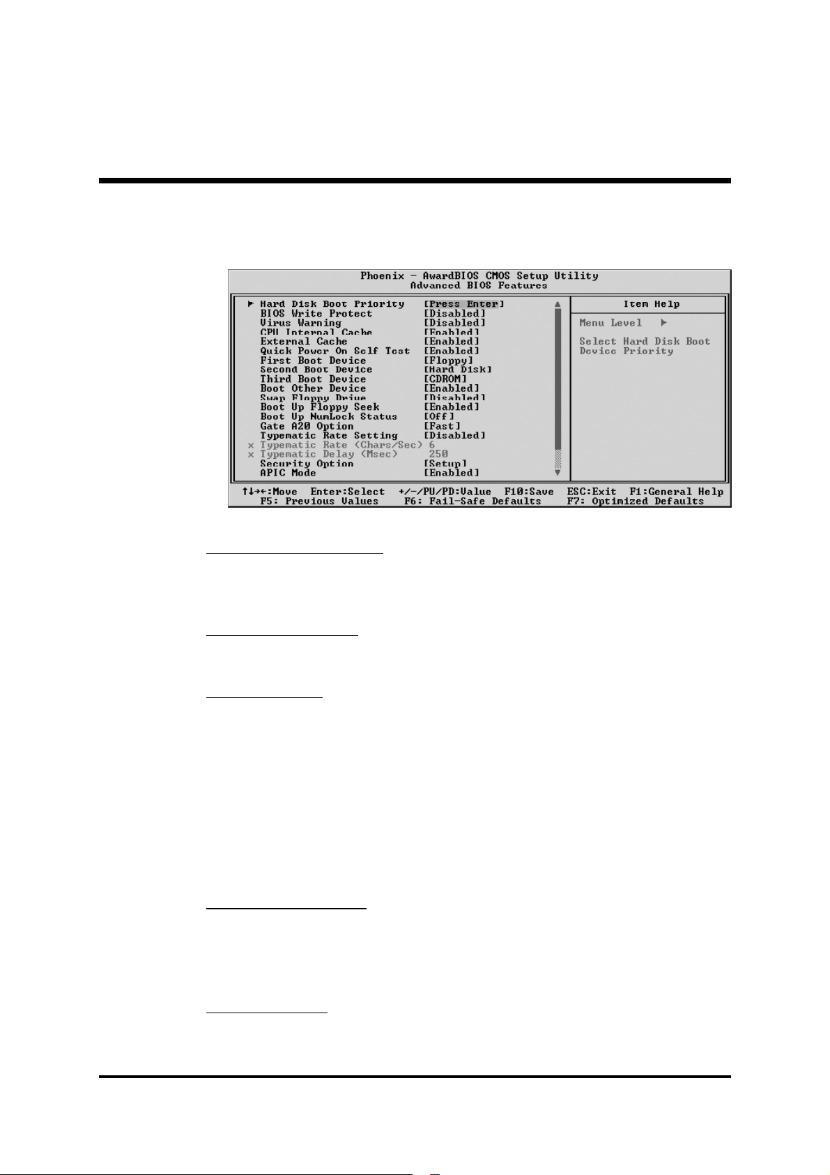
@ Advanced BIOS Features
This section allows you to configure your system for basic operation.
Hot Disk Boot Priority
This item let you select hot disk boot priority.
Ø The choice: Pri.Master/Slave, Sec.Master/Slave, USB HDD 0~2,
Bootable Add-in Cards.
BIOS Write Protect
This item let you enable or disable the BIOS Write Protect.
Ø The choice: Enabled or Disabled.
Virus Warning
Allows you to choose the VIRUS Warning feature for IDE Hard Disk boot
sector protection. Enable this item to prevent someone from writing data
into this area.
Enabled Activates automatically when the system boots up, caus-
ing a warning message to appear when anything attempts
to access the boot sector or hard disk partition table.
Disabled No warning message will appear when anything attempts
to access the boot sector or hard disk partition table.
Ø The choice: Enabled or Disabled.
CPU Internal Cache
All processors that can be installed in this mainboard use internal level
1 (L1) cache memory to improve performance. Leave this item at the
default value for better performance.
Ø The choice: Enabled or Disabled.
External Cache
Most processors that can be installed in this system use external level 2
(L2) cache memory to improve performance. Leave this item at the
default value for better performance.
- 53 -
Page 61

Ø The choice: Enabled or Disabled.
Quick Power On Self Test
Enable this item to shorten the power on testing (POST) and have your
system start up faster. You might like to this item after you are confident
that your system hardware is operating smoothly.
Ø The choice: Enabled or Disabled.
First/Second/Third Boot Device
Use these three items to select the priority and order of the devices that
your system searches for an operating system at start-up time.
Ø The Choice: Floppy, LS120, Hard disk, CDROM, ZIP100, USBFDD, USB-ZIP,USB-CDROM, Legacy LAN or Disabled.
Boot Other Device
If you enable this item, the system searches all other possible locations
for and operating system if it fails to find one in the devices specified
under the First, Second, and Third boot devices.
Ø The choice: Enabled or Disabled.
Swap Floppy Drive
If you have two floppy diskette drives in your system, this item allows
you to swap the assigned drive letters so that drive A becomes drive B,
and drive B becomes drive A.
Ø The choice: Enabled or Disabled.
Boot Up Floppy Seek
If this item is enabled, it checks the size of the floppy disk drives at startup time. You don't need to enable this item unless you have a legacy
diskette drive with 360k capacity.
Ø The choice: Enabled or Disabled.
Boot Up NumLock Status
This item defines if the keyboard Num Lock key is active when your
system is started.
Ø The choice: Off or On.
Gate A20 Option
This item defines how the system handles legacy software that was
written for an earlier generation of processors. Leave this item at the
deafult value.
Ø The choice: Normal or Fast.
Typematic Rate Setting
If this item is enabled, you can use the following two items to see the
typematic rate and the typematic delay settings for your keyboard.
Ø The choice: Enabled or Disabled.
- 54 -
Page 62

Typematic Rate (Chars/Sec)
This item sets how many times the keystroke will be repeated in a
second when you hold a key down.
Ø The choice: 6, 8, 10, 12, 15, 20, 24, or 30.
Typematic Delay (Msec)
Sets the delay time after a key is held down.
Ø The choice: 250, 500, 750, or 1000.
Security Option
If you have installed password protection, this item defines if the password is required at system start up, or if it is only required with a user
tries to enter the Setup Utility.
Ø The choice: Setup or System.
APIC Mode
This option is used to enable or disable APIC (Advanced Programmable
Interrupt Controller) functionality.
Ø The choice: Enabled or Disabled.
MPS Version Control For OS
Selects the operating system multiprocessor support version.
Ø The choice: 1.1 or 1.4
OS Select For DRAM > 64MB
This item is only required if you have installed more than 64 MB of
memory and you are running the OS/2 operating system. Otherwise,
leave this item at the default.
Ø The choice: Non-OS2 or OS2.
Small Logo(EPA) Show
This item allows you to enable or disable the EPA Logo.
Ø The choice: Enabled or Disabled.
- 55 -
Page 63
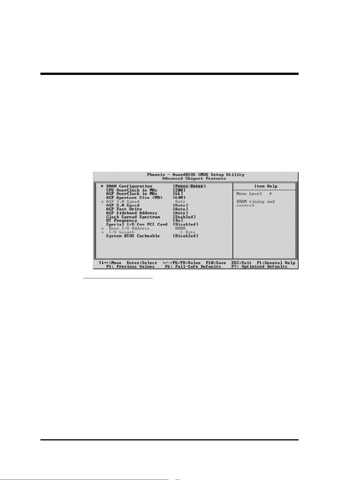
@ Advanced Chipset Features
This section allows you to configure the system based on the specific
features of the installed chipset. This chipset manages bus speeds and
access to system memory resources, such as DRAM and the external
cache. It also coordinates communications between the conventional PCI
bus. It states that these items should never need to be altered.
The default settings have been chosen because they provide the best
operating conditions for your system. If you discovered that data was being lost while using your system, you might consider making any charges.
DRAM Configuration
Options are in its sub-menu.
Press<Enter> to enter the sub-menu of detailed options.
Max Memclock (Mhz)
Places an artificial memory clock limit on the system.
Memory is prevented from running faster than this frequency.
Ø The choice: Auto,100,133 or 166.
CAS# latency
When synchronous DRAM is installed, the number of clock cycles of
CAS latency depends on the DRAM timing. Don't change this field
from the default value specified by the system designer.
Ø The choice: Auto, CL=2.0, CL=2.5 or CL=3.0.
RAS# to CAS# delay (tRCD)
This field let you insert a timing delay between the CAS and RAS trobe
signals, and you can use it when DRAM is written to, read from, or
refreshed. Faster performance is gained in high speed, more stable
performance, in low speed. This field is applied only when synchronous DRAM is installed in the system.
Ø The choice: Auto, 2~7 Bus Clocks.
- 56 -
Page 64

Min RAS# active time (tRAS)
The item defines the numbers of cycles for RAS to be allowed to
precharge.
Ø The choice: Auto, 5~15 Bus Clocks.
Row precharge Time (tRP)
If an insufficient number of cycles is allowed for the RAS to accumulate
its charge before DRAM refresh, the refresh may be-incompleted, and
the DRAM may fail to retain data. Fast gives faster performance; and
Slow gives more stable performace. This field is applied only when
synchronous DRAM is installed in the system.
Ø The choice: Auto, 2~6 Bus Clocks.
1T/2T Memory Timing
The item defines the memory timing for CPU version CG or after.
Ø The choice: Auto, 1T or 2T.
CPU OverClock in MHz
This item selects the CPU OverClock in MHz.
Ø The choice: 200~280.
AGP OverClock MHz
This item selects the AGP OverClock in MHz.
Ø The choice: 66~100.
AGP Aperture Size(MB)
Select the size of Accelerated Graphics Port (AGP) aperture.
The aperture is a portion of the PCI memory address range dedicated to
graphics memory address space. Host cycles that hit the aperture range
are forwarded to the AGP without any translaton.
Ø The choice: 32M,64M,128M,256M or 512M.
AGP 3.0 Speed
This item allows you to set the AGP 3.0 Speed.
Ø The choice: Always Auto.
AGP 2.0 Speed
This item allows you to set the AGP 2.0 Speed.
Ø The choice: Auto,1x,1x2x or 1x2x4x.
AGP Fast Write
This item allows you to set the AGP Fast Write.
Ø The choice: Auto or Disabled.
AGP Sideband Address
This item auto/disable the AGP sideband addressing capability for AGP
Card.
Ø The choice: Auto or Disabled.
- 57 -
Page 65

Clock Spread Spectrum
This item allows you to set the Clock spread spectrum modulation.
Ø The choice: Enabled or Disabled.
HT Frequency
This item allows you to set the HT Frequency.
Ø The choice: 1X, 2X, 3X, 4X or 5X.
Special I/O for PCI Card
This item enable/disable the Special I/O for PCI Card.
Ø The choice: Enabled or Disabled.
Base I/O Address
This item allows you to set the Base I/O Address.
Ø The choice: 0000~FFFF.
I/O Length
This item allows you to set the I/O Length.
Ø The choice: 1 Byte, 4 Bytes, 8 Bytes, 16 Bytes, 32 Bytes, 64 Bytes,
128 Bytes or 256 Bytes.
System BIOS Cacheable
Select Enable allows caching of the system BIOS ROM at F000h~FFFFFh,
resulting in better system performance. However, if any program is writen
to this memory area, a system error may result.
Ø The choice: Enabled or Disabled.
- 58 -
Page 66
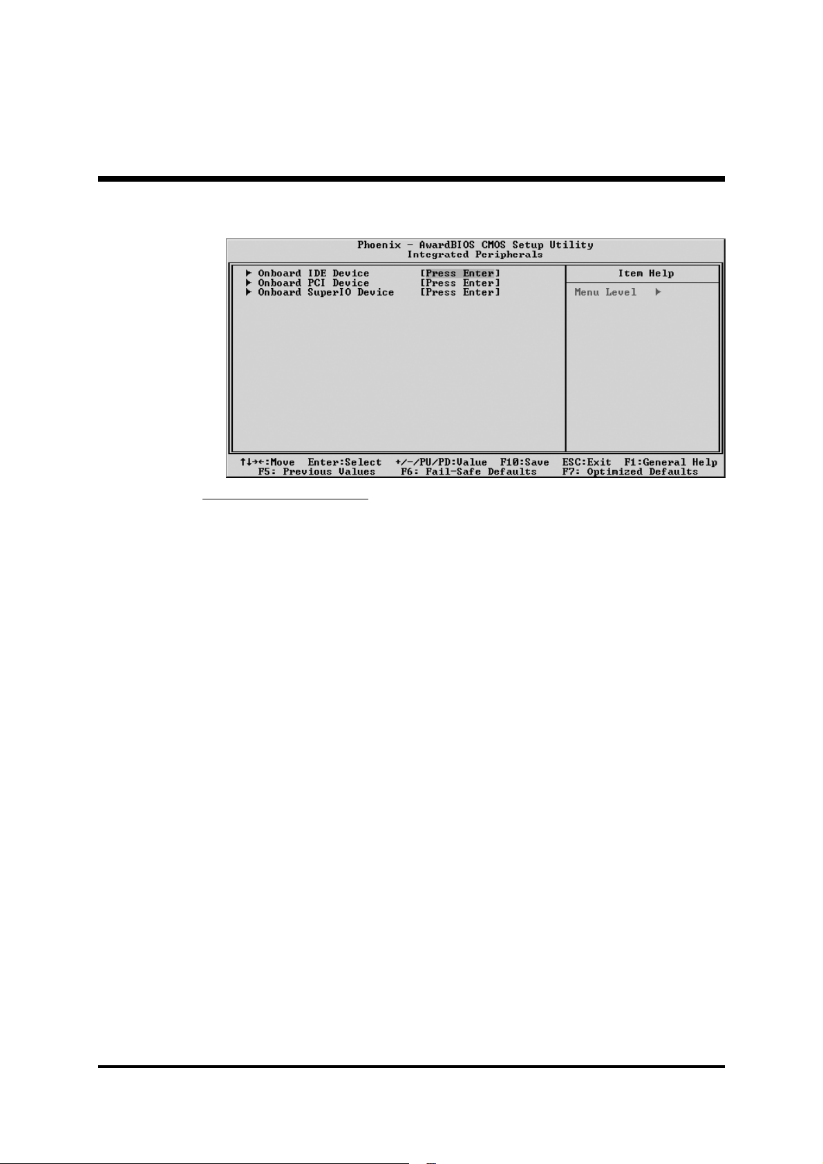
@ Integrated Peripherals
Onboard IDE Device
Press <Enter> to enter the sub-menu of detailed options.
Raid Function Setup
Press <Enter> to enter the sub-menu of detailed options.
IDE RAID, IDE Channel 0/1 Master/Slave RAID or SATA/
SATA-2 Primary/Secondary Master RAID.
The item allows you to set raid function.
Ø The Choice: Enabled or Disabled.
OnChip IDE Channel 0/1
The chipset contains a PCI IDE interface with support to two IDE chan-
nels. Select Enabled to activate the primary/secondary IDE interface.
Select Disabled to deactivate the primary/secondary interface.
Ø The Choice: Enabled or Disabled.
Primary/Secondary Master/Slave PIO
The four IDE PIO (Programmed Input/Output) fields let you set a PIO
mode (0-4) for each of the two IDE devices that the onboard IDE interface supports. Modes 0 through 4 provide successively increased
performance. In Auto mode, the system automatically determines the
best mode for each device.
Ø The choice: Auto, Mode 0, Mode 1, Mode 2, Mode 3, or Mode 4.
Primary/Secondary Master/Slave UDMA
Ultra DMA implementation is possible only if your IDE hard drive
supports it and the operating environment includes a DMA driver
(Windows 95 OSR2 or a third-party IDE bus master driver). If both of
your hard drive and your system software support Ultra DMA, select
Auto to enable BIOS support.
Ø The choice: Auto or Disabled.
- 59 -
Page 67

IDE Prefetch Mode
The onboard IDE drive interface support IDE prefetching for faster drive
access. If you install a primary and/or secondary add-on IDE interface,
set this field to Disabled if the interface does not support prefetching.
Ø The Choice: Enabled or Disabled.
Serial-ATA (External PHY)
This item allows you to enable or disable Serial-ATA (External PHY).
Ø The Choice: Enabled or Disabled.
Serial-ATA2 (Internal PHY)
The item allows you to enable or disable Serial-ATA2 (Internal PHY).
Ø The Choice: Enabled or Disabled.
IDE DMA transfer access
Use these items to enable or disable the IDE DMA transfer access that
are intergrated on the mainboard.
Ø The Choice: Enabled or Disabled.
IDE HDD Block Mode
Block mode is also called block transfer, multiple commands, or mul-
tiple sector read/write. If your IDE hard drive supports block mode (most
new drivers do), select Enabled for automatic detection of the optimal
number of block read/write per sector the drive can support.
Ø The Choice: Enabled or Disabled.
Onboard PCI Device
Press <Enter> to enter the sub-menu of detailed options.
Init Display First
This item is used to determine initial device when system power on.
Ø The choice: PCI Slot or AGP Slot.
OnChip USB
Do not disable this item if your system has a USB installed on the sys-
tem board and you want to use it.
Ø The choice: Disabled, V1.1+V2.0, or V1.1.
USB KB/Storeage Support
Select Enabled if your system contains a Universal Serial Bus (USB)
controller and you have a USB keyboard.
Ø The Choice: Enabled or Disabled.
OnChip Audio
This item allows you to control the OnChip Audio.
Ø The Choice: Auto or Disabled.
- 60 -
Page 68

Broadcom Gb/FE LAN ROM
This item allows you to enable or disable the the Gb/FE LAN ROM.
Ø The Choice: Enabled or Disabled.
Onboard Super I/O Device
Press <Enter> to enter the sub-menu of detailed options.
Onboard FDC Controller
This item specifices onboard floppy disk drive controller. This setting
allows you to connect your floppy disk drives to the onboard floppy
connector.
Ø The choice: Enabled or Disabled.
Onboard Serial Port 1
The option is used to assign the I/O address and interrupt request (IRQ)
for the onboard serial port 1 (COM1).
Ø The Choice: Disabled, 3F8-IRQ4, 2F8-IRQ3, 3E8-IRQ4, 2E8-IRQ3
or Auto.
Onboard Infrared Port
This option is used to assign the I/O address and interrupt request (IRQ)
for the onboard infrared port.
Ø The Choice: Disabled, 3F8-IRQ4, 2F8-IRQ3, 3E8-IRQ4, 2E8-IRQ3,
or Auto.
UART Mode Select
This item allows you to select an operating mode for the IrDA infrared.
Ø The choice: IrDA, ASKIR or SCR.
UR2 Duplex Mode
This item allows you to select the IR half or full duplex function.
Ø The choice: Full or Half.
Onboard Parallel Port
Allows you to determine an I/O address and interrupt request (IRQ) for
the onboard parallel port.
Ø The choice: 378/IRQ7, 278/IRQ5, 3BC/IRQ7 or Disabled.
Parallel Port Mode
Select an operating mode for the onboard parallel port. Select SPP
unless you are certain your system supports other modes.
Ø The choice: SPP, EPP, ECP or ECP+EPP.
ECP Mode Use DMA
When the parallel port mode is set to ECP, this item becomes seletable.
Ø The choice: 1 or 3.
- 61 -
Page 69
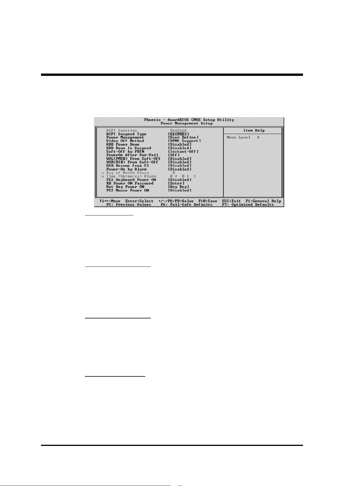
@ Power Management Setup
The Power Management Setup allows you to configure your system to
most effectively saving energy while operating in a manner consistent
with your own style of computer use.
ACPI Function
This item defines the ACPI (Advanced Configuration and Power Management) feature that makes hardware status information available to
the operating system, enables a PC to turn its peripherals on or off for
improving the power management, and allows a PC turned on or off by
external devices, so that a mouse or keyboard can wake up it.
ACPI Suspend Type
This item allows you to select sleep state when suspend. In the default,
S1(POS), the suspend mode is equivalent to a software power down;
S3(STR), to the system that shuts down with the exception of a refresh
current to the system memory.
Ø The choice: S1(POS), S3(STR), or S1&S3.
Power Management
This item acts like a master switch for the power-saving modes and hard
disk timeouts. If this item is set to Max Saving, power-saving modes
occur after a short timeout. If it is set to Min Saving, power-saving
modes occur after a longer timeout. If it is set to User Define, you can
insert your own timeouts for the power-saving modes.
Ø The choice: Min Saving, Max Saving or User Define.
Video Off Method
This determines the manner in which the monitor is blanked.
V/H SYNC+Blank This selection will cause the system to turn off
Blank Screen The item only writes blanks to the video buffer.
DPMS Support Initial display power management signaling.
Ø The choice: V/H SYNC+Blank, Blank Screen, or DPMS Support.
the vertical and horizontal synchronization
ports and write blanks to the video buffer.
- 62 -
Page 70

HDD Power Down
The IDE hard drive will spin down if it is not accessed within a specified
length of time. Options are from 1 Min to 15 Min and Disabled.
Ø The choice: Disabled or 1 Min~15 Min.
HDD Down In Suspend
The item allows you to enable or disable the HDD Down In Suspend.
Ø The choice: Enabled or Disabled.
Soft-Off by PBTN
Under ACPI you can create a software power down. In a software
power down, the system can be resumed by Wake UP Alarms.
Ø The choice: Delay 4 Sec or Instant-Off.
PWRON After PWR-Fail
This item defines your computer to shut off or automatically restart.
Ø The choice: Former-Sts, Off or On.
WOL(PME#) From Soft-Off
If this item sets to Enabled, the system power will be turned on when the
LAN port receives an incoming signal.
Ø The choice: Enabled or Disabled.
WOR(RI#) From Soft-Off
If this item is enabled, it allows the system to resume from a software
power down or power-saving mode whenever there is an incoming call
to an installed fax/modem. You have to connector the fax/modem to
the mainboard.
Ø The choice: Enabled or Disabled.
USB Resume from S3
If you are using USB devices, and the ACPI Suspend Type is set to S3 or
S1&S3, enable this item to have USB devices wake up the system from
power saving mode.
Ø The choice: Enabled or Disabled.
Power-On by Alarm
When set to Enabled, the following four fields become available and
you can set the date, hour, minute and second to turn on your system.
Ø The choice: Enabled or Disabled.
Day of Month Alarm
This item selects the alarm date.
[dd] Ø Key in a DEC number: Min=0, Max=31.
Time(dd : hh : mm) of Alarm
This item selects the alarm time.
[hh] Ø Key in a DEC number: Min=0, Max=23.
[mm] Ø Key in a DEC number: Min=0, Max=59.
[ss] Ø Key in a DEC number: Min=0, Max=59.
- 63 -
Page 71
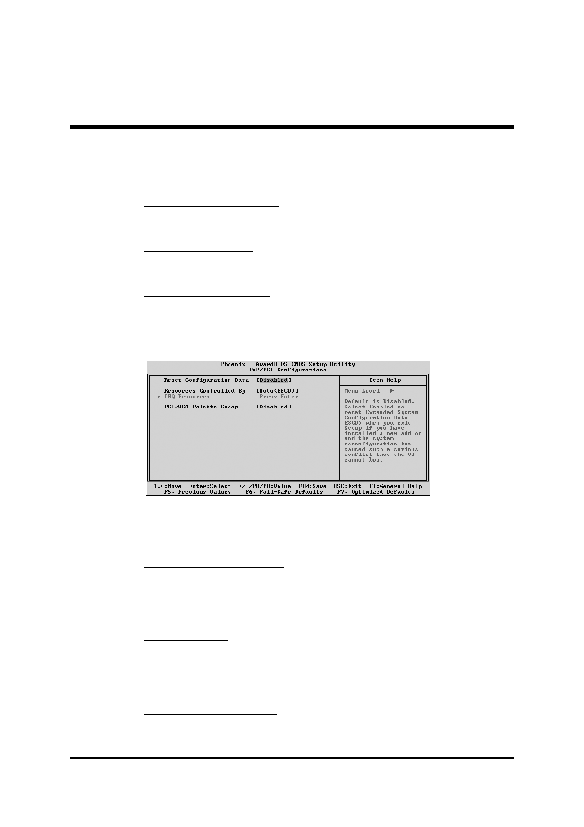
PS2 Keyboard Power ON
Set a key to awaken the system from a PS2 keyboard.
Ø The choice: Password, Hot KEY or Disabled.
KB Power ON Password
Press <Enter> to set a password to awaken the system from a keyboard.
Hot Key Power ON
Set a key to awaken the system from a keyboard.
Ø The choice: Any Key or Ctrl-F1~F12.
PS2 Mouse Power ON
Set a key to awaken the system from a PS2 mouse.
Ø The choice: Enabled or Disabled.
@ PnP/PCI Configurations
This category configures how PnP and PCI operate in your system.
Reset Configuration Data
When enabled, any PnP configuration data stored in the BIOS will be
cleared from memory, with new data created.
Ø The choice: Enabled or Disabled.
Resources Controlled By
As stays auto(ESCD), the system will dynamically allocate resources to
PnP devices as they are required. As set to manual, the following item
become available.
Ø The choice: Auto(ESCD) or Manual.
IRQ Resources
When the previous item is set to manual, this item allows you respectively assign an interruptive type for IRQ-3, 4, 5, 7, 9, 10, 11, 12, 14,
and 15.
Ø The choice: PCI Device or Reserved.
PCI/VGA Palette Snoop
The item is designed to solve problems caused by some non-standard
VGA cards.
Ø The choice: Enabled or Disabled.
- 64 -
Page 72
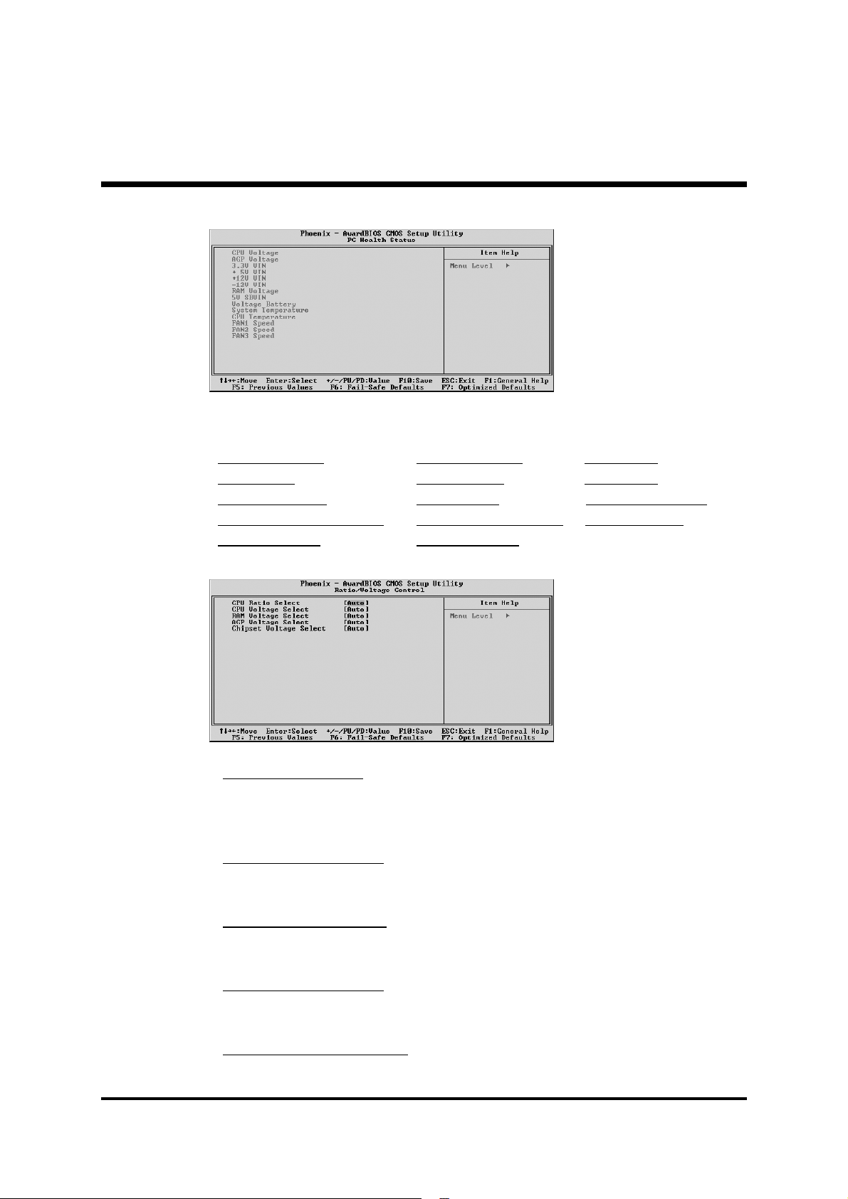
@ PC Health Status
The following items provide you with information about the system's
current operating status. You cannot make changes to one of them.
CPU Voltage AGP Voltage 3.3V VIN
+5V VIN +12V VIN -12V VIN
RAM Voltage 5V SBVIN Voltage Battery
System Temperature CPU Temperature FAN1 Speed
FAN2 Speed FAN3 Speed
@ Ratio/Voltage Control
CPU Ratio Select
This item allows you to adjust CPU Ratio.
Ø The choice: Auto, X4 800 MHz, X5 1000 MHz, X6 1200 MHz~
X20 4000 MHz.
CPU Voltage Select
This item allows you to adjust CPU Voltage.
Ø The choice: Auto, 0.800V~1.700V.
RAM Voltage Select
This item allows you to adjust RAM Voltage.
Ø The choice: Auto, 2.70 V, 2.80V or 2.90 V.
AGP Voltage Select
This item allows you to adjust AGP Voltage.
Ø The choice: Auto, 1.60 V, 1.70V or 1.80 V.
Chipset Voltage Select
This item allows you to adjust chipset Voltage.
Ø The choice: Auto, 1.70 V,1.80V or 1.90 V.
- 65 -
Page 73
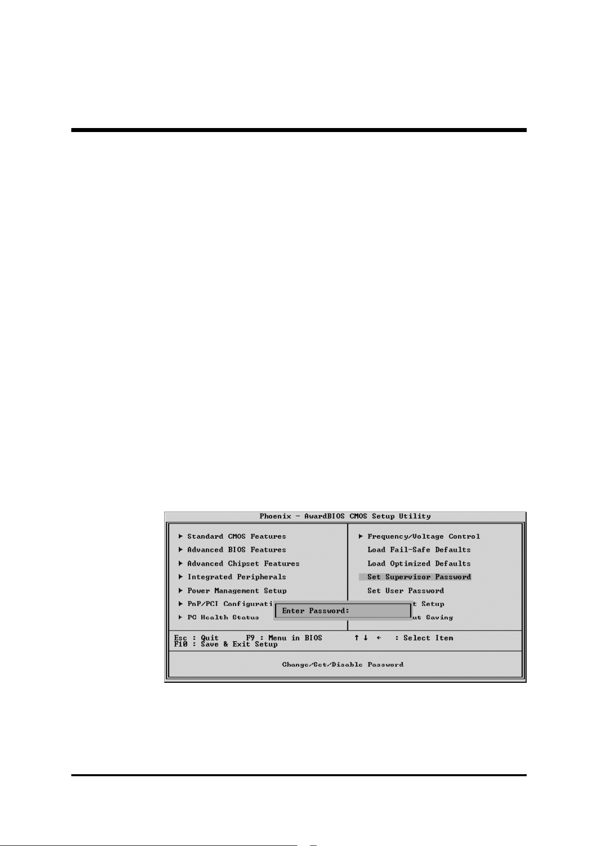
@ Load Fail-Safe Defaults
When you press <Enter> on this item, you will get a confirmation
dialog box with a message similar to:
Load Fail-Safe Defaults (Y/N) ? N
Pressing 'Y' loads the BIOS default values for the most stable, minimal
performance system operations.
@ Load Optimized Defaults
When you press <Enter> on this item, you will get a confirmation
dialog box with a message similar to:
Load Optimized Defaults (Y/N) ? N
Pressing 'Y' loads the default values that are factory-set for optimal
performance system operation.
@ Set Supervisor/User Password
Steps to set supervisor/user password are described as follows:
- 66 -
Page 74

New Password Setting:
1. While pressing <Enter> to set a password, a dialog box appears to
ask you enter a password.
2. Key in a new password. The password can not exceed eight characters.
3. System will request you to confirm the new password again.
4. When completed, new code takes effect.
No Password Setting:
If you want to disable the password, just press <Enter> as a password
input is requested.
If You Forget Password:
If you forget the password, the only way to access the system is to clear
the CMOS memory. Please refer to page 28 on clear CMOS setting.
@ Save & Exit Setup
Pressing <Enter> on this item asks for confirmation:
SAVE to CMOS and EXIT (Y/N)? Y
Pressing "Y" stores the selections made in the menus of CMOS - a
special section of memory that stays on after you turn your system off.
The next time you boot your computer, the BIOS configures your
system according to the Setup selections stored in CMOS. After saving
the values the system is restarted again.
@ Exit Without Saving
Pressing <Enter> on this item asks for confirmation:
Quit Without Saving (Y/N)? N
This allows you to exit from Setup without storing in CMOS any
change. The previous selections remain in effect. This exits from the
Setup utility and restarts your computer.
- 67 -
Page 75

Appendix A. Update Memory Configurations:
Unbuffered DIMM Support
No.of dimms DIMM 1 DIMM 2 DIMM 3 Max Speed 1T Max Speed 2T
1 SS DDR 400 DDR 400
1 SS DDR 400 DDR 400
1 SS DDR 400 DDR 400
1 DS DDR 400 DDR 400
1 DS DDR 400 DDR 400
1 DS DDR 400 DDR 400
2 SS SS DDR 400 DDR 400
2 SS DS DDR 400 DDR 400
2 SS SS DDR 400 DDR 400
2 SS DS DDR 400 DDR 400
2 DS SS DDR 400 DDR 400
2 DS DS DDR 400 DDR 400
2 DS SS DDR 400 DDR 400
2 SS SS DDR 333 DDR 400
2 SS DS DDR 200 DDR 400
2 DS SS DDR 200 DDR 400
2 DS DS DDR 200 DDR 333
2 DS DS DDR 400 DDR 400
3 SS SS SS DDR 333 DDR 400
3 SS SS DS DDR 200 DDR 333
3 SS DS SS DDR 200 DDR 333
3 SS DS DS DDR 200 DDR 333
3 DS SS SS DDR 333 DDR 333
3 DS SS DS DDR 200 DDR 333
3 DS DS SS DDR 200 DDR 333
3 DS DS DS DDR 200 DDR 333
SS: x8 single rank or x16
DS: x8 double rank
- 68 -
 Loading...