

Page 1

AK10
AMD Socket-A Based
MAIN BOARD
User's Manual
Page 2

Shuttle AK10
AMD Socket-A based Mainboard
Manual Version 1.0
Copyright
Copyright© 2000 by Shuttle Inc. All Rights Reserved.
No part of this publication may be reproduced, transcribed, stored in a retrieval system,
translated into any language, or transmitted in any form or by any means, electronic,
mechanical, magnetic, optical, chemical, photocopying, manual, or otherwise, without
prior written permission from Shuttle Inc.
Disclaimer
Shuttle Inc. shall not be liable for any incidental or consequential damages resulting from the
performance or use of this product.
This company makes no representations or warranties regarding the contents of this manual.
Information in this manual has been carefully checked for reliability; however, no guarantee is
given as to the correctness of the contents. In the interest of continued product improvement,
this company reserves the right to revise the manual or include changes in the specifications
of the product described within it at any time without notice and without obligation to notify any
person of such revision or changes. The information contained in this manual is provided for
general use by the customers.
Trademarks
Spacewalker is a registered trademark of Shuttle Inc.
VIA is a registered trademarks of VIA Corporation.
PS/2 is a registered trademark of IBM Corporation.
AWARD is a registered trademark of Award Software Inc.
Microsoft and Windows are registered trademarks of Microsoft Corporation.
General Notice: Other brand and product names used herein are for identification
purposes only and may be trademarks of their respective owners.
M386
Page 3

TABLE OF CONTENTS
WHAT’S IN THE MANUAL ....................................................................... 4
Quick Reference........................................................................................................... 4
About This Manual....................................................................................................... 4
1 INTRODUCTION.................................................................................... 5
1.1 TO DIFFERENT USERS....................................................................................... 5
FIRST-TIME DIY SYSTEM BUILDER............................................................... 5
EXPERIENCED DIY USER .............................................................................. 5
SYSTEM INTEGRATOR .................................................................................... 5
1.2 ITEM CHECKLIST.................................................................................................. 6
2 FEATURES............................................................................................. 7
2.1 SPECIFICATIONS .................................................................................................. 7
3 HARDWARE INSTALLATION............................................................. 10
3.1 STEP BY STEP INSTALLATION .......................................................................10
Accessories Of AK10 ......................................................................................10
STEP 1 Install the CPU.................................................................................... 11
STEP 2 Set Jumpers .......................................................................................12
STEP 3 Install SDRAM System Memory .......................................................12
STEP 4 Install Internal Peripherals in System Case .....................................13
STEP 5 Mount the Mainboard on the Computer Chassis............................14
STEP 6 Connect Front Panel Switches/LEDs/Speaker ..............................15
STEP 7 Connect IDE & Floppy Disk Drives..................................................17
STEP 8 Connect Other Internal Peripherals ..................................................18
STEP 9 Connect the Power Supply................................................................18
STEP 10 Install Add-on Cards in Expansion Slots .......................................19
- 1 -
Page 4

STEP 11 Connect External Peripherals to Back Panel................................20
STEP 12 First Time System Boot Up .............................................................22
STEP 13 Install Drivers & Software Components.........................................23
3.2 JUMPER SETTINGS ...........................................................................................24
Jumpers & Connectors Guide .........................................................................25
Enable On Board Sound Chip (JP12) ............................................................28
Hardware Monitor (JP13).................................................................................28
Clear CMOS (JP14) .........................................................................................29
Thermal Sense (JP26,JP27) ...........................................................................30
IR Connector (JP9) ...........................................................................................30
PS/2 Keyboard & PS/2 Mouse Connectors ..................................................31
USB1 / USB2 Port Connectors .......................................................................31
COM1 Connector..............................................................................................31
Parallel Port Connector ....................................................................................31
Speaker and Line-In and Mic Header.............................................................32
MIDI/GAME Port................................................................................................32
KEYLOCK Connector (KEYLOCK) ................................................................33
HDD LED Connector (HDD LED) ..................................................................33
Speaker Connector (SPEAKER)....................................................................33
ATX Power On/Off Switch Connector (SPWR)..............................................34
POWER LED (PWRLED)................................................................................34
Hardware Reset Connector (RESET) ............................................................34
Enhanced IDE and Floppy Connectors ..........................................................35
ATX Power Connector......................................................................................36
CPU Fan and Housing Fan Connector (CPU FAN, FAN2)..........................36
CD Audio Connector (CD_IN).........................................................................37
AUX_IN Connector (AUX_IN)..........................................................................37
- 2 -
Page 5

COM2 Connector (COM2)...............................................................................37
USB3/USB4 Ports (USB2)..............................................................................38
Wake On Lan Connector (WOL) .....................................................................38
PC-Doctor Debug LED....................................................................................39
3.3 SYSTEM MEMORY CONFIGURATION ............................................................41
Install Memory....................................................................................................41
Upgrade Memory..............................................................................................41
4 SOFTWARE UTILITY.......................................................................... 42
4.1 AK10 MAINBOARD CD OVERVIEW...............................................................42
4.2 INSTALL MAINBOARD SOFTWARE ..............................................................43
4.3 INSTALL Audio Device SOFTWARE..............................................................44
4.4 INSTALL VIA Hardware Monitor .....................................................................45
4.5 VIEW THE USER'S MANUAL ..........................................................................46
5 BIOS SETUP ........................................................................................ 47
5.1 ENTER THE BIOS ...............................................................................................47
5.2 THE MAIN MENU .................................................................................................48
Standard CMOS Setup ....................................................................................50
Advanced BIOS Features................................................................................52
Advanced Chipset Features............................................................................56
Integrated Peripherals ......................................................................................60
Power Management Setup ..............................................................................65
PnP / PCI Configurations .................................................................................69
PC Health Status ..............................................................................................71
Frequency/Voltage Control..............................................................................72
Load Setup/Turbo Defaults..............................................................................73
User Password Setting ....................................................................................74
Save & Exit Setup/Exit without Saving ...........................................................76
- 3 -
Page 6

WHAT’S IN THE MANUAL
Quick Reference
Hardware Installation >> Step-by-Step...................................................... Page 10
Jumper Settings >> A Closer Look ............................................................ Page 24
Software Utility >> How to Install ................................................................ Page 42
BIOS Setup >> How to Configure ............................................................... Page 47
About This Manual
For First-Time DIY System Builder ................................................................Page 5
For Experienced DIY User ...............................................................................Page 5
For System Integrator.......................................................................................Page 5
- 4 -
Page 7

1 INTRODUCTION
1.1 To Different Users
First-Time DIY System Builder
Welcome to the DIY world! Building your own computer system is not as
difficult as you may think. To make your first computer DIY experience
successful, right from the start, we have designed the 3 Hardware Installation
section in a step-by-step fashion for all the first-time DIY system builders. Prior
to installation, we also suggest you to read the whole manual carefully to gain
a complete understanding of your new AK10 mainboard.
Experienced DIY User
Congratulate on your purchase of the Shuttle AK10 mainboard. You will find
that installing your new Shuttle AK10 mainboard is just easy. Bundled with an
array of onboard functions, the highly-integrated AK10 mainboard provides
you with a total solution to build the most stable and reliable system. Refer to
sections 3.2 Jumper Settings and Chapter 4 Software Utility to find out how to
get the best out of your new mainboard. Chapter 5 BIOS Setup also contains
the relevant information on how to tune up your system to achieve higher performance.
System Integrator
You have wisely chosen Shuttle AK10 to construct your system. Shuttle
AK10 incorporates all the state-of-the-art technology of the VT8363 chipset
from VIA. It integrates the most advanced functions you can find to date in a
compact ATX board. Refer to sections 3.2 Jumper Settings and Chapter 4
Software Utility for an in-depth view of system construction.
- 5 -
Page 8

1.2 Item Checklist
SOCKET462
Check all items with your AK10 mainboard to make sure nothing is missing.
The complete package should include:
- One Shuttle AK10 Mainboard
- One ATA/66 Ribbon Cable
- One Floppy Ribbon Cable
- One 9-pin COM2 Cable
AK10 MB
00113 SB
48 36K01 OSB
-
+
KT133
VT82C686A0021CG TAIWAN
13CON3400
AWARD 1999
PCI/PNP K7202062269
C
MC
- AK10 User’s Manual
- One CD-ROM containing:
Ø AK10 user’s manual on PDF format
Ø VIA 4 IN 1 Drivers
Ø Audio Device Software
Ø VIA Hardware Monitor
Ø Award Flashing Utility
- 6 -
Page 9

2 FEATURES
AK10 mainboard is carefully designed for the demanding PC user who wants high
performance and maximum intelligent features in a compact package.
2.1 Specifications
-- CPU Support
Supports AMD Athlon Processor 600 ~ 1000+ MHz
and AMD Duron Processor 600 ~ 750+ MHz
-- Chipset
Features VIA Apollo KT133 Chipset VT8363 with super south I/O bridge
VT82C686A, and 200MHz EV6 Bus.
-- Jumperless CPU Configuration
Soft-configure CPU Speed (The CPU operating speed is software
configurable from Frequency/Voltage Control of BIOS Setup program.
-- Versatile Memory Support
Equipped with three DIMM banks of PC66/100/133 compliant SDRAM
and VCM SDRAM to provide up to 1.5GB of system memory.
Configurable support to EC (Error Checking) and ECC (Error Checking and
Correcting).
-- AGP Slot
A component level of device interconnected to AGP cards which supports
up to 4x Accelerated Graphics Port cards for high performance and is
directed to the 3D graphical display application.
-- PCI Expansion Slots
Provides five 32-bit PCI slots.
-- Super I/O Interface:
Provides a variety of I/O interfaces:
Ø 1 × Floppy interface for 3.5-inch FDD with 720KB, 1.44MB, 2.88MB
format or for 5.25-inch FDD with 360KB or 1.2MB format.
- 7 -
Page 10

Ø 1 × PS/2 mouse connector
Ø 1 × PS/2 Keyboard connector
Ø 2 ports of USB connectors on back panel
Ø One set of 2-port USB headers on front panel
Ø 2 × DB9 Serial connectors 16550 UART compatible
Ø 1 × Infrared communication port ASKIR and HPSIR compatible.
(Serial port COM2 can also be redirected to an external IrDA Adapter
for wireless connection.)
Ø 1 × DB25 Parallel port supporting Standard Parallel Port (SPP),
Enhanced Parallel Port (EPP) and Extended Capabilities Port (ECP)
data transmission schemes.
Ø 1 x DB15 MIDI/GAME port , and another 3 ports which are Speaker,
Line-In and Mic.
-- PCI Bus Master IDE Controller Onboard
Two Ultra DMA 33/66 Bus Master Dual-channel IDE ports provide support to a
maximum of four IDE devices (one Master and one Slave per channel). The
IDE Bus implements the data transfer speed up to 33/66 MB/sec and also supports Enhanced PIO Modes 0 ~ 4.
-- ATX Power Supply Connector
ATX power supply unit can be connected to the onboard 20-pin ATX power
connector, supporting Suspend and Soft-On/Off by dual-function power
button.
-- Advanced Configuration and Power Interface
Features four power saving modes: Snoop, Suspend to RAM, Suspend to
Disk, and Soft-Off. ACPI provides more efficient Energy Saving Features
controlled by your operating system that supports OS Direct Power Management (OSPM) functionality.
-- System BIOS
Provides licensed Award BIOS on 2Mb Flash EEPROM.
Supports Green PC and Desktop Management Interface (DMI) and bundled
with NCR SCSI BIOS.
- 8 -
Page 11

-- ATX Form Factor
System board conforms to the ATX specification.
Board dimension: 304mm × 244mm
-- Advanced Features
Ø Dual Function Power Button - The system can be in one of two states;
one is Suspend mode and the other is Soft-Off mode. Pushing the power
button for less than 4 seconds places the system into Suspend mode.
When the power button is pressed for longer than 4 seconds, the system
enters the Soft-Off mode.
Ø Wake-on-LAN (WOL) - The onboard WOL connector can be attached to
a network card that supports this function to wake up the system via LAN.
ØModem Ring Power-On - The system can be powered on automatically
by the activation of modem ring.
-- Other Features
Ø Hardware Monitoring - This motherboard implements a hardware moni-
toring system. As you turn on your system, this smart design will continue
to monitor your system's working voltage, fan status and CPU temperature.
If any of these systems's status goes wrong, there will be an alarm through
the VIA Hardware Monitoring Utility to warn the user.
Ø PC-Doctor Debug LED (Optional) - In conjunction with PC Doctor (Op-
tional). The DR. LED can easily show what kind of problem you may incur
on your system during assembly. It can clearly indicate whether there is a
component issue or an installed issue by the 8 LEDs on front panel of PCDoctor. This helps you quickly self diagnostic your system status.
Ø Thermal Sensor (Optional) - With the increasing performance, the compo-
nents nowadays always generate enormous heat inside the system, such as
CPU, VGA card, HDD, and so on. In the meanwhile, they're the most
important components while we concern about the stability of the system.
The thermal sensor provides a convenient and flexible way of an extensible sensor for users to detect the temperature of any component.
Ø RAM Power LED - This LED indicates there is power which applies to
memory. It is useful to check RAM power during Suspend to RAM. Don
not unplug memory module when this LED is On.
- 9 -
Page 12

3 HARDWARE INSTALLATION
Before removing or installing any of these devices including CPU, DIMMs, Add-On
Cards, Cables, Please make sure to unplug the onboard power connector.
This section outlines how to install and configure your AK10 mainboard. Refer to the
following mainboard layout to help you identify various jumpers, connectors, slots, and
ports. Then follow these steps designed to guide you through a quick and correct installation of your system.
3.1 Step-by-Step Installation
Accessories Of AK10
ATX Power Connector
PS2 Keyboard/
PS/2 Mouse Connectors
USB1/USB2Connectors
CPU FAN Connector
Socket 462
Serial Port Connector
(COM1)
Parallel Connector
VIA KT133 Chipset
200MHz EV6 Bus
Speaker/Line_In/Mic
MIDI/GAME Port Connectors
AGP 2x/4x Slot
PC133 DIMM
CD_IN Connector-CN11
Onboard Sound Setting -JP12
AUX_IN Connector-CN20
H/W Monitor-JP13
AC97 Audio CODEC
Five PCI Slots
RAM POWER LED2
(Optional)
VT8373
CPU Thermal Sense
- JP26 (Optional)
SOCKET462
C
VT82C686A
0021CG TAIWAN
13CON3400
AWARD
1999
C
U22
RN52
PCI/PNP K7
202062269
Two IDE Connectors
Floppy Connector
JP9 IRDA
IrDA Connector-JP9
Serial Port Connector(COM2)- CN17
USB3/USB4 header- CN15
Wake On Lan Connector- CN16
2Mb Flash ROM
Clear CMOS- JP14
DR. LED-CN19
- 10 -
AK10 MB
00113 SB
-
48 36K01 OSB
Housing Fan- FAN2
System Thermal
Sense- JP27(Optional)
Front Panel Connectors- CN18
Page 13

Step 1
SOCKET462
Install the CPU:
1. Locate the CPU socket on the upper-rightsector of your mainboard (between the back panel connectors and the DIMM memory banks).
2. Pull the CPU socket lever slightly sideways away from the socket
to unlock the lever, and then bring it to an upwardly vertical position.
3. Place your AMD 462 Athlon/Duron processor in the socket A. Note that
the CPU’s edges have been purposely designed non-symmetrically to
prevent from inserting the processor in the wrong direction. And the CPU
will only fit in the orientation as shown. The following diagram demonstrates the correct placement of the CPU in socket A. You can see that the
two blunt-edged corners should be oriented toward the blank space on
the socket.
Blank
AMD CPU
SOCKET462
Lever Blank
ASSEMBLED IN MALAYSIA
Notch
4. Slightly push the AMD 462 Athlon/Duron processor into the socket without applying excessive force while making sure there is no gap between
CPU and socket. Then lower the socket-lever all the way down to the
horizontal position and lock it to secure the CPU in place.
5. The AMD 462 Athlon/Duron processor requires a set of heatsink/fan to
ensure proper cooling of the processor. If the heatsink/fan have not been
mounted on your CPU, you must purchase the heatsink/fan separately and
have it installed. Plug the cable through the heatsink/fan in the CPU fan
power connector located nearby. Note that there are several types of CPU
fan connectors. Normally, if your mainboard supports the hardware
monitoring function, a 3-pin fan power connector should allow your
system to detect the CPU fan’s speed . The CPU fan can also run with a 2pin fan power connector, however, detection of CPU fan’s speed is not
supported. Another type of CPU fan may feature a large 4-pin fan power
connector, which does not support CPU fan's speed detection and must
be directly connected to the system’s power supply unit.
- 11 -
Page 14

Step 2.
Set Jumpers
This mainboard is jumperless! The default jumper settings have been set for
the common usage standard of this mainboard. Therefore, you do not need
to reset the jumpers unless you require special adjustments as any of the
following cases:
1. Clear CMOS
2. Disable the onboard audio before installing an add-on sound card
For first-time DIY system builders, we recommend that you should not
change the default jumper settings if you are not totally familiar with
mainboard configuration procedures. The factory-set default settings are
tuned for optimum system performance. For the advanced users who wish to
customize their system, section 3.2 Jumper Settings will provide the detailed
information on how to configure your mainboard manually.
Step 3
Install SDRAM System Memory
To install memory, insert SDRAM or VCM SDRAM memory module(s) in any
one, two or three DIMM banks. Note that SDRAM modules are directional
and will not go in the DIMM slots unless they are properly oriented. After the
module is fully inserted into the DIMM socket, lift the clips of both sides of the
DIMM bank to lock the module in place.
- 12 -
Page 15

Step 4
Install Internal Peripherals in System Case
Before you install and connect the mainboard into your system case, we
recommend that you first assemble all the internal peripheral devices into the
computer housing, including but not limited to the hard disk drive (IDE/
HDD), floppy disk drive (FDD), CD-ROM drive, and ATX power supply unit.
This will greatly facilitate in making the connection to the mainboard described below.
To install IDE & FDD drives, follow this procedure:
1. Set the required jumpers on each device according to the instructions
provided by the manufacturer. (IDE devices, HDD and CD-ROM, must
have jumpers on Master or Slave mode depending on your willing to
install more than one device for each kind.
2. Connect IDE cable and FDD cable to the back panel of the internal
peripheral devices. Note that the cable should be oriented with its
colored stripe (usually in red or magenta) connected to pin#1 both on the
mainboard IDE or FDD connector and on the device as well.
3. Connect an available power cable through your system power supply unit
to the back panel of each peripheral device. Note that the power cable is
directional and cannot fit in if not properly positioned.
- 13 -
Page 16

Step 5
Mount the Mainboard on the Computer Chassis
1. You may find that there are a lot of different mounting hole positions
both on your computer chassis and on the mainboard. To choose a
correct mounting hole, the key point is to keep the back panel of the
mainboard in a close fit with your system case, as shown below.
2. After deciding the proper mounting holes, position the studs between
the frame of chassis and the mainboard. The studs are used to fix the
mainboard and to keep a certain distance between the system chassis
and the mainboard, in order to avoid any electrical short between the
board and the metal frame of chassis. (If your computer case is already
equipped with mounting studs, you will need to tighten screws to attach
the mainboard.)
Note: In most computer housings, you will be able to find 4 or more
attachment points to install mounting studs and fix the mainboard.
If there aren’t enough matching holes, then make sure to install at
least 3 mounting studs to ensure proper attachment of the
mainboard.
- 14 -
Page 17

Step 6
Connect Front Panel Switches/LEDs/Speaker
You can find there are several different cables already existing in the system
case and originating from the computer’s front-panel devices (HDD LED,
Power LED, Reset Switch, PC Speaker, etc.) These cables serve to connect the
front-panel switches and LEDs to the mainboard’s front-panel connectors
group, as shown below :
CN18
PANEL
RESET
+
LED
+
SPWR PWR LED
1. KEYLOCK (KEYLOCK)
HDD
LED
HDD
+ +
1
KEYLOCK SPEAKER
2. HDD LED (HDD LED)
RESET
CN18
PANEL
SPWR PWR LED
RESET
CN18
PANEL
SPWR PWR LED
SPEAKER
+
+
+
1
+
1
HDD
HDD
+
KEYLOCK
+
+
HDD
HDD
+
KEYLOCK SPEAKER
LED
LED
LED
LED
- 15 -
Page 18

3. SPEAKER (SPEAKER)
RESETSPWR PWR LED
4. Power Switch (SPWR) ATX Soft Power On/Off
5. POWER LED (PWRLED)
CN18
PANEL
RESET
CN18
PANEL
SPWR PWR LED
+
++
+
1
LED
HDD
LED
HDD
KEYLOCK SPEAKER
SPEAKER
+
++
+
1
LED
HDD
LED
HDD
KEYLOCK
- 16 -
RESET
CN18
PANEL
SPWR PWR LED
SPEAKER
+
+
+
1
HDD
HDD
+
KEYLOCK
LED
LED
Page 19

6. RESET (RESET)
RESET
Step 7
Connect IDE & Floppy Disk Drives
1. IDE cable connector
CN13
CN12
CN18
PANEL
SPWR PWR LED
+
+
+
1
HDD
HDD
+
KEYLOCK SPEAKER
LED
LED
2. Floppy cable connector
IDE 1
FDC CN14
- 17 -
1
1
IDE 2
1
Page 20

Step 8
Connect Other Internal Peripherals
1. IR connector
Step 9
Connect the Power Supply
1. System power connector
JP9
1
IRDA
- 18 -
Page 21

Step 10
Install Add-on Cards in Expansion Slots
1. Accelerated Graphics Port (AGP) Card
2. PCI Card
- 19 -
Page 22

Step 11
Connect External Peripherals to Back Panel
You are now ready to put the computer case back together and get on to the
external peripherals connections to your system’s back panel.
KB / MSCN2
CN3 USB
CN4
CN7
MIDI/GAME
1. PS/2 Mouse and PS/2 Keyboard
PS/2 Mouse
2. USB Devices
3. COM Port
PS/2 keyboard
USB1 & USB2
COM1
- 20 -
Page 23

4. Parallel Port
5. Audio Speaker/Line_In/Mic
6. MIDI/Game Port
Parallel Port
Speaker Line_In Mic
- 21 -
MIDI/GAME Port
Page 24

Step 12
First Time System Boot-Up
To assure the completeness and correctness of your system installation, you
may check the above installation steps once again before you boot up your
system for the first time.
1. Insert a bootable system floppy disk (DOS 6.2x, Windows 95/98/NT, or
others) which contains FDISK and FORMAT utilities into the FDD.
2. Turn on the system power.
3. First, you must use the FDISK utility to create a primary partition of the
hard disk. You can also add an extended partition if your primary partition does not use all of the available hard disk space. If you choose to
add an extended partition, you will have to create one or more logical
partitions to occupy all the space available in the extended partition. The
FDISK utility will assign a drive letter (i.e., C:, D:, E:,...) to each partition
which will be shown in the FDISK program. After FDISK procedure,
reboot your system by using the same system floppy disk.
Note: DOS 6.2x and Windows 95A can only support up to 2.1GB of
HDD partition. If you use the FDISK utility with one of the
operating systems mentioned above, you can only install your
HDD into partitions no larger than 2.1GB each.
4. Now, use the FORMAT utility to format all the partitions you’ve created.
When formatting the primary partition (C:), make sure to use the
FORMAT C: /S command.
Note: FORMAT C: /S can transfer all the necessary system files into the
primary partition of your hard disk. Then, your HDD will become
a bootable drive.
5. Install all the necessary drivers for CD-ROM, Mouse, etc.
6. Set up the complete operating system according to your OS installation
guide.
- 22 -
Page 25

Step 13
Install Drivers & Software Components
Please note that all the system utilities and drivers are designed for Win 9x
operating systems only. Make sure your Windows 9x operating system is
already installed before running the driver installation CD-ROM programs.
1. Insert the AK10 bundled CD-ROM into your CD-ROM drive. The
auto-run program will display the driver main installation window on
screen .
2. Choose " Install Mainboard Software" and complete it.
3. Return to the SHUTTLE MAINBOARD SOFTWARE SETUP screen.
4. Choose "Install Audio Device Software" and complete it.
5. Return to the SHUTTLE MAINBOARD SOFTWARE SETUP screen.
6. Choose "Install VIA Hardware Monitor" and complete it.
7. Return to the main installation window and exit from the auto-run
drivers installation program.
- 23 -
Page 26

3.2 Jumper Settings
Several hardware settings are made through the use of jumper caps to connect jumper pins to the mainboard. Pin #1 is located at any corner of each
jumper; you just find a location with white right angle, which stands for pin
1#. There are several types of pin1# shown as below:
3-pin and multi-pin (>3) jumpers are shown as follows:
Pin #1 to the left:
Pin #1 on the top:
Pin #1 to the right:
1
1
1
1
Pin #1 on the bottom:
1
Jumpers with two pins are shown as for Close [On] or for
Open [Off]. To Short jumper pins, simply place a plastic jumper cap over the
desired pair of pins.
Caution!
1. Do not remove the mainboard from its antistatic protective packaging
until you are ready to install it.
2. Carefully hold the mainboard by its edges and avoid touching its
components. When putting the mainboard down, place it on the top of its
original packaging film, and on an even surface, and components side up.
3. Wear an antistatic wrist strap or take other suitable measures to prevent
electrostatic discharge (ESD) whenever handling this equipment.
- 24 -
Page 27

Jumpers & Connectors Guide
Use the mainboard layout on page 10 to locate CPU socket, memory banks,
expansion slots, jumpers and connectors on the mainboard during the installation. The following list will help you to identify jumpers, slots, and connectors along with their assigned functions:
E1
B1
B2
B3~B4
E2
B5~B8
A2
E4
A1
E5
E7
E6
E8
A3
A5
F1
D1
D1
A6
C1~C6
A4
F2
E3
E9
CPU/Memory/Expansion Slots
Socket 462 : CPU Socket for socket 462 AMD Athlon and Duron
processors.
DIM1/2/3 : Three DIMM Sockets for 16,32,64,128,256,512MB 3.3V
SDRAM and VCM SDRAM.
AGP : One AGP (Accelerated Graphics Port) Slot
PCI : Five 32-bit PCI Expansion Slots
- 25 -
Page 28

Jumpers
JP12 : On board sound setting.
A1
JP13 : Hardware monitor.
A2
JP14 : Clear CMOS.
A3
JP27 : System thermal sense.
A4
JP26 : CPU thermal sense.
A5
JP9 : IrDA.
A6
Back Panel Connectors
KB : PS/2 Keyboard.
B1
MS : PS/2 Mouse.
B1
USB : 2 × USB (Universal Serial Bus).
B2
COM1 : Serial Port 1 (DB9 male).
B3
PRINTER : Parallel Port (DB25 female).
B4
SPEAKER : Speaker port.
B5
LINE_IN : Line_in port.
B6
B7
MIC : Mic_in port.
B8
GAME/MIDI : GAME/MIDI port.
Front Panel Connectors
KEYLOCK : Enable or disable keyboard.
C1
HDD LED : IDE Drive Active LED.
C2
C3
SPEAKER : Speaker in housing.
C4
SPWR : ATX Power On/Off Momentary Type Switch.
PWR LED : System Power LED.
C5
C6
RESET : Hardware Reset Switch.
Internal Peripherals Connectors
D1
FDC : Floppy Disk Drive Interface
IDE1 : IDE Primary Interface (Dual-channel)
D1
D1
IDE2 : IDE Secondary Interface (Dual-channel)
- 26 -
Page 29

Other Connectors:
Power : ATX power connector (20-pin header).
E1
CPU FAN : CPU fan connector.
E2
E3
FAN2 : Housing fan connector.
E4
CD_IN : Audio CD_IN connector.
E5
AUX_IN : Audio AUX_IN connector.
E6
COM2 : COM2 connector.
E7
USB2 : USB3 and USB4 ports header
E8
WOL : Wake on lan connector.
E9
DR. LED : PC-Doctor debug LED connector.
- 27 -
Page 30

A1
111
1
Enable On Board Sound Chip (JP12)
This motherboard has AC97 sound onboard. JP12 is used to enable or disable onboard AD1885 CODEC chip. If you do not want to enable the
Onboard Audio, you should set this jumper to 2-3, and disable the "OnChip
Sound" from BIOS setting > Advanced Chipset Features, before you install
your preferred PCI Sound Card.
Pin 1-2
(Default- enable on board sound chip)
Pin 2-3
(Disable on board sound chip)
A2
Hardware Monitor (JP13)
This motherboard implements a hardware monitoring system. As you turn on
your system, this smart design will continue to monitor your system's working
voltage, fan status and CPU temperature. If any of these systems's status goes
wrong, there will be an alarm through the VIA Hardware Monitor Utility to
warn the user.
(Enable hardware monitor function)
JP12
1
JP13
1
(Disable hardware monitor function)
- 28 -
Page 31

A3
Clear CMOS (JP14)
JP14 is used to clear CMOS data. Clearing CMOS will result in permanently
erasion of previous system configuration settings and restoration of the original (factory-set) system settings.
Step 1. Turn off the system power (PC-> Off)
Step 2. Remove mini jumpers from JP2 pins 1-2
Step 3. Place the mini jumpers on JP2 pin 2-3
for a few seconds
Step 4. Return the mini jumpers to pin 1-2
Pin 1-2 (Default, Normal)
JP14
Pin 2-3 (Clear CMOS)
1
Step 5. Turn on the system power (PC-> On)
- 29 -
Page 32

A4~A5
Thermal Sense (JP26, JP27) (Optional)
With the increasing performance, the components nowadays always generate enormous heat inside the system, such as CPU, VGA card, HDD, and so
on. In the meanwhile, they are the most important components while we
concern about the stability of the system. The thermal sensor provides a
convenient and flexible way of an extensible sensor for users to detect the
temperature of any component.
For example, you can just plug the
sliced sensor into the narrow
opening between CPU and heat-
CPU Thermal
Sense
1
sink to monitor accurate temperature.
System Thermal
Sense
1
A6
IR Connector (JP9)
The IrDA connector can be configured to support wireless infrared module,
with this module and application software such as Laplink or Windows 95
Direct Cable Connection, the user can transfer files to or from laptops, notebooks, PDA devices and printers. This connector supports HPSIR
(115.2Kbps, 2 meters) and ASK-IR (56Kbps).
Install the infrared module onto the IrDA connector and enable the infrared
function from BIOS Setup, Integrated Peripherals > UART 2 Mode, make
sure to have the correct orientation when you plug in the IrDA connector.
JP26
JP27
Pin assignment :
1 +5V
NC
IRRX
GND
IRTX
+5V
1
JP9 IRDA
- 30 -
Page 33

PS/2 Keyboard & PS/2 Mouse Connectors
B1
Two 6-pin female PS/2 keyboard & Mouse
connectors are located at the rear panel
of the mainboard. Depending on the computer housing you use (desktop or
minitower), the PS/2 Mouse connector is
situated at the top of the PS/2 Keyboard
connector when the mainboard is laid into
a desktop, as opposite to a minitower
where the PS/2 Mouse connector is located at the right of the PS/2 Keyboard's.
Plug the PS/2 keyboard and mouse jacks
into their corresponding connectors.
B2
USB1/USB2 Port Connectors
Two female connectors USB1/USB2 share
the same USB (Universal Serial Bus)
bracket at the rear panel of your
mainboard. Plug each USB device jack
into an available USB1/USB2 connector.
PS/2 Mouse
PS/2 keyboard
USB1 & USB2
B3
COM1 Connector
This mainboard can accommodate one
serial device on COM1. Attach a serial device cable to the DB9 serial port COM1 at
the back panel of your computer.
Parallel Port Connector
B4
One DB25 female parallel connector is
located at the rear panel of the mainboard.
Plug the connection cable from your parallel device (printer, scanner, etc.) into this
connector.
COM1
Parallel Port
- 31 -
Page 34

B5
Speaker
B6
Line_In
B7
Mic
Line_Out is a stereo output port
through which the combined signal of
all internal and external audio sources
on the board is output. It can be connected to 1/8-inch TRS stereo headphones or to amplified speakers.
Line_In is a stereo line-level input port
that accepts a 1/8-inch TRS stereo
plug. It can be used as a source for
digital sound recording, a source to be
mixed with the output, or both.
MIC_IN is a 1/8-inch jack that provides
a mono input. It can use a dynamic
mono or stereo microphone with a
resistance of not more than 600
Ohms.
Speaker
Line_In
Mic
B8
MIDI/GAME Port
The MIDI/GAME port is a 15-pin female connector. This port can be connected to any IBM PC compatible
game with a 15-pin D-sub connector.
MIDI Instrument Connection
You will need a MIDI adapter to
connect a MIDI compatible instrument to the sound card. The MIDI
adapter can in turn be connected
to the Joystick/MIDI port. You will
also need the MIDI sequencing
software to run MIDI instruments
with your computer.
MIDI/GAME Port
- 32 -
Page 35

C1
KEYLOCK Connector (KEYLOCK)
Keylock connector is a 2-pin connector
for a lock that may be installed on the system case for enabling or disabling keyboard.
RESET
PANEL
+
LED
HDD
LED
HDD
+ ++
C2
HDD LED Connector (HDDLED)
Attach the connector cable from the IDE
device LED to the 2-pin HDD LED header.
The HDD LED lights up whenever an IDE
device is active.
Note : Please notice all the LED connectors are directional. If your chassis’s
LED does not light up during running, please simply change to the
opposite direction.
SPWR PWR LED
RESETSPWR PWR LED
PANEL
+
KEYLOCK SPEAKER
1
SPEAKER
+
+
LED
HDD
LED
HDD
+
1
KEYLOCK
C3
Speaker Connector (SPEAKER)
Attach the PC speaker cable from the case
to the 4-pin speaker connector (SPEAKER).
- 33 -
RESETSPWR PWR LED
PANEL
+
SPEAKER
+
+
LED
HDD
LED
HDD
+
KEYLOCK
1
Page 36

C4 ATX Power On/Off Switch Connector (SPWR)
The Power On/Off Switch is a momentary
type switch used for turning on or off the
system’s ATX power supply. Attach the
connector cable from the Power Switch
to the 2-pin PWON header on the
mainboard.
RESET
PANEL
+
+
+
+
SPEAKER
LED
HDD
C5
POWER LED (PWRLED)
Attach the 2-pin Power-LED connector
cable from the housing's front panel to the
PWR LED header on the mainboard. The
power LED stays light while the system is
running.
C6
Hardware Reset Connector (RESET)
Attach the 2-pin hardware reset
switch cable to the RST header.
Pressing the reset switch causes the
system to restart.
SPWR PWR LED
RESETSPWR PWR LED
PANEL
+
RESET
PANEL
+
PWR LED
KEYLOCK
1
SPEAKER
+
LED
HDD
LED
HDD
+ +
KEYLOCK
1
SPEAKER
+
LED
HDD
LED
HDD
+ +
- 34 -
SPWR
KEYLOCK
1
Page 37

Enhanced IDE and Floppy Connectors
D1
The AK10 mainboard features two 40-pin dual-channel IDE device connectors (IDE1/IDE2) providing the support to up to four IDE devices, such as CDROM and Hard Disk Drives (H.D.D.). This mainboard also includes one 34pin floppy disk controller (FDD) to accommodate the Floppy Disk Drive
(F.D.D.). Moreover, this mainboard comes with one 40pin ribbon cable to
connect to IDE H.D.D. and one 34-pin ribbon cable for F.D.D. connection.
Note : Please connect your system H.D.D. to IDE 1.
Important: Ribbon cables are directional, therefore, make sure to always
connect with the red cable stripe on the same side as pin #1 of
the IDE1/IDE2 or FDC connector on the mainboard.
CN13
IDE 1
FDC CN14
CN12
IDE 2
11
1
- 35 -
Page 38

E1
ATX Power Connector
Locate the 20-pin male header ATX power connector (ATX PWR) on your
mainboard. Plug the power cable from the ATX power supply unit directly
into ATX PWR ATX power supply connector.
Note 1 :The ATX power connector is directional and will not go in unless
the guides match perfectly. Make sure that pin#1 is properly
positioned.
Note 2: Make sure the latch of the ATX power connector clicks into place
to ensure a solid attachment.
E2~E3
Note 3: Your ATX power supply must be supplied to ACPI +5V standby
power and at least 720mA compatible.
Note 4: Make sure your power supply have enough power for higher
speed processor installed.
CPU Fan and Housing Fan Connector (CPU FAN, FAN2)
This mainboard provides two onboard 12V cooling fan power connectors to
support CPU (CPU FAN), Housing Fan (FAN2) cooling fans.
Note: Both cable wiring and type of plug may vary depending on the
fan maker. Keep in mind that the red wire should always be
connected to the 12V header and the black wire to the ground
(GND) header.
CPU FAN
SENSE
+12
GND
FAN2
- 36 -
Page 39

Audio CD_IN Connector (CD_IN)
1
10
E4
This connector is used to connect CD Audio cable from CDROM or DVD
drive to onboard sound.
Pin assignment :
1 L
GND
GND
R
E5
AUX_IN Connector (AUX_IN)
This connector is used to connect MPEG Audio cable from MPEG card to
onboard sound.
Pin assignment :
1 L
GND
GND
R
CD_IN
1
CN11
AUX_IN
1
CN20
E6
COM2 Connector (COM2)
This motherboard comes with one 10-pin ribbon cable for COM2.
Pin assignment :
DCD2 RX2
TX2
GND
RTS2
R12
DTR2
DSR2
CTS2
NC
COM2
1
- 37 -
CN17
Page 40

Dual USB3/USB4 Ports Header (USB2)
1
10
E7
This header is used to connect the cable attached to USB connectors
mounted front panel.
Pin assignment:
NCNC
GND
+3D
-3D
+5V
E8
Wake-on LAN Connector (WOL)
GND
+2D
-2D
+5V
Attach a 3-pin connector from the LAN card which supports the Wake-OnLAN (WOL) function. This function lets users wake up the connected system
through LAN card.
USB2 CN15
1
+5V Standby
GND LID
WOL CN16
- 38 -
Page 41

PC-Doctor Debug LED (Optional)
E9
In conjunction with PC Doctor (Optional). The DR. LED can easily show
what kind of problem you may incur on your system during assembly. It
can clearly indicate whether there is a component issue or an installed
issue by the 8 LEDs on the front panel of PC-Doctor. This helps you quickly
self diagnostic your system status.
LED 1
PC-Doctor is a CD disc storage box with 8 LEDs on its front panel, the size
of PC-Doctor is exactly the same as 5.25 in floppy drive, so that it can be
mounted into normal 5.25 in drive bay of any housing.
DR. LED
CN19
1
7 6 5 4 3 2 1 0
Boot O.K. KB HDD FDD PCI Video Memory CPU
The total 8 LEDs light-up alternatively if the system fails in one of eight
stages. Once the LED 7 (latest LED) is lit, this indicates that the system has
completed its boot-up procedure.
The 8 LEDs indicate the following messages when lit:
LED 0 - Indicate that the CPU may have been installed incorrectly or is
damaged.
LED 1 - Indicate that the memory may have been installed incorrectly or is
damaged.
LED 2 - Indicate that the AGP may have been installed incorrectly or is
damaged.
- 39 -
Page 42

LED 3 - Indicate that the PCI card may have been installed incorrectly or is
damaged.
LED 4 - Indicate that the floppy disk drive may have been installed incorrectly or is damaged.
LED 5 - Indicate that the HDD may have been installed incorrectly or is
damaged.
LED 6 - Indicate that the keyboard may have been installed incorrectly or
is damaged.
LED 7 - Indicate that the system is OK.
Note: During POST (power on self test) procedure, the Debug LED will
light on sequentially from LED 0 to LED 7 until the system boot up successfully.
- 40 -
Page 43

3.3 System Memory Configuration
The AK10 mainboard has three 168-pin DIMM sockets that allow you to
install from 16MB up to 1.5GB of system memory with PC66/100/133
SDRAM (Synchronous DRAM) and VCM (Virtual Channel Memory) SDRAM.
Each DIMM (Dual In-line Memory Module) socket can accommodate 16MB,
32MB, 64MB, 128MB, 256MB and 512MB 3.3V single or double side 64 or
72-bit wide data path SDRAM and VCM SDRAM modules.
The AK10 mainboard supports data integrity algorithms including EC (Error
Checking) and ECC (Error Checking and Correction) in the memory array. In
EC mode, single and multiple bit error detection is provided. In ECC mode,
when the memory is being read from DRAM, the AK10 provides both the
error checking and the correction of the data.
Install Memory:
Install memory in any or all of the banks and in any combination, shown as
follows :
DIMM Socket Memory Modules
DIMM 1
DIMM 2
DIMM 3
16MB, 32MB, 64MB, 128MB, 256MB and 512MB
168-pin 3.3V SDRAM and VCM SDRAM DIMM
16MB, 32MB, 64MB, 128MB, 256MB and 512MB
168-pin 3.3V SDRAM and VCM SDRAM DIMM
16MB, 32MB, 64MB, 128MB, 256MB and 512MB
168-pin 3.3V SDRAM and VCM SDRAM DIMM
Module
Quantity
x 1
x 1
x 1
Note: You do not need to set any jumper to configure memory since the
BIOS utility can detect the system memory automatically. You can
check the total system memory value in the BIOS Standard CMOS
Setup menu.
Upgrade Memory:
You can easily upgrade the system memory by inserting additional SDRAM
and VCM SDRAM modules in available DIMM banks. The total system
memory is calculated by simply adding up the memory in all DIMM banks.
After upgrade, the new system memory value will automatically be computed
and displayed by the BIOS Standard CMOS Setup menu.
- 41 -
Page 44

4 SOFTWARE UTILITY
4.1 AK10 Mainboard CD Overview
Note: The cd contents attached in the AK10 mainboard are subject to
change without notice.
To start your mainboard CD, just insert it into your CD-ROM drive, and the
CD AutoRun screen should appear. If the AutoRun screen does not appear,
double click or run D:\Autorun.exe (assuming that your CD-ROM drive is
drive D:)
Navigation Bar Description:
FF Install Mainboard Software - Installing Mainboard Drivers for
Windows
FF Install Audio Device Software - Installing Audio Driver
FF Install VIA Hardware Monitor - Installing VIA Hardware
Monitor Driver
FF Manual - AK10 series mainboard user's manual in PDF format.
FF Link to Shuttle Homepage - Link to shuttle website homepage.
FF Browse this CD - Allows you to see the contents of this CD.
FF Quit - Close this CD.
- 42 -
Page 45

4.2 Install Mainboard Software
Insert the attached CD into your CD-ROM drive, and the CD AutoRun screen
should appear. If the AutoRun screen does not appear, double click on
Autorun icon in My Computer to bring up Shuttle Mainboard Software
Setup screen.
Use your pointing device (e.g. mouse) to select the “Install Mainboard Soft-
ware” bar.
Once you made your selection, a Setup window runs the installation automatically.
When the copying files is done, make sure you reboot the system to take the
installation effect.
- 43 -
Page 46

4.3 Install Audio Device Software
Insert the attached CD into your CD-ROM drive, and the CD AutoRun screen
should appear. If the AutoRun screen does not appear, double click on
Autorun icon in My Computer to bring up Shuttle Mainboard Software
Setup screen.
Use your pointing device (e.g. mouse) to select the “Install Audio Device
Software” bar.
Once you made your selection, a Setup window runs the installation
automatically.
When the copying files is done, make sure you reboot the system to
take the installation effect.
- 44 -
Page 47

4.4 Install VIA Hardware Monitor
Insert the attached CD into your CD-ROM drive and the CD AutoRun screen
should appear. If the AutoRun screen does not appear, double click on
Autorun icon in My Computer to bring up Shuttle Mainboard Software
Setup screen.
Use your pointing device (e.g. mouse) to select the “Install VIA Hardware
Monitor ” bar.
Once you made your selection, a Setup window runs the installation
automatically.
When the copying files is done, make sure you reboot the system to
take the installation effect.
- 45 -
Page 48

4.5 View the User's Manual
Insert the attached CD into your CD-ROM drive and the CD AutoRun screen
should appear. If the AutoRun screen does not appear, double click on
Autorun icon in My Computer to bring up Shuttle Mainboard Software
Setup screen.
Use your pointing device (e.g. mouse) to select the “Manual” bar.
Then the Online Information windows will appear on your screen. Click on
the “Install Acrobe Reader 4.05” bar if you need to install acrobe reader.
Then click on "AK10 Manual" bar to view AK10 user's manual.
- 46 -
Page 49

5 BIOS SETUP
AK10 BIOS ROM has a built-in Setup program that allows users to modify the
basic system configuration. This information is stored in
battery-backed RAM so that it retains the Setup information even if the system
power is turned off.
The system BIOS is managing and executing a variety of hardware related
functions in the system, including:
System date and time
Hardware execution sequence
Power management functions
Allocation of system resources
5.1 Enter the BIOS
To enter the BIOS (Basic Input / Output System) utility, follow these steps:
Step 1. Power on the computer, and the system will perform its
POST (Power-On Self Test) routine checks.
Step 2. Press <Del> key immediately, or at the following message:
“Press DEL to enter SETUP”
,or simultaneously press <Ctrl>, <Alt>, <Esc> keys
Note 1. If you miss trains of words mentioned in step 2 (the message disap
pears before you can respond) and you still wish to enter BIOS
Setup, restart the system and try again by turning the computer OFF
and ON again or by pressing the <RESET> switch located at the
computer’s front panel. You may also reboot by simultaneously
pressing the <Ctrl>, <Alt>, <Del> keys.
Note 2. If you do not press the keys in time and system does not boot, the
screen will prompt an error message, and you will be given the
following options:
“Press F1 to Continue, DEL to Enter Setup”
Step 3. As you enter the BIOS program, the CMOS Setup Utility will
prompt you the Main Menu, as shown in the next section.
- 47 -
Page 50

5.2 The Main Menu
Once you enter the AwardBIOS(tm) CMOS Setup Utility, the Main Menu will
appear on the screen. The Main Menu allows you to select from several
setup functions and two exit choices. Use the arrow keys to select among the
items and press <Enter> to accept and enter the sub-menu.
Note that a brief description of each highlighted selection appears at the
bottom of the screen.
Standard CMOS Features
This setup page includes all items in a standard BIOS compatible.
Advanced BIOS Features
This setup page includes all items of Award special enhanced features.
Advanced Chipset Features
This setup page includes all items of chipset features.
Integrated Peripherals
This setup page includes all items of peripherals features.
Power Management Setup
This setup page includes all items of Power Management features.
PnP/PCI Configurations
This item specifies the value (in units of PCI bus blocks) of the latency
timer for the PCI bus master and the IRQ level for PCI device. Power-on
the system with BIOS defaults.
- 48 -
Page 51

PC Health Status
This entry shows the current system temperature, voltage and Fan
speed.
Frequency/Voltage Control
Use this menu to specify your settings for frequency/voltage control.
Load Setup Defaults
Setup defaults load the optimized settings for optimum system performance. However, you can change the parameter through each Setup
Menu.
Load Turbo Defaults
To load the Turbo defaults is required by the power users who want to
push the limitation of system performance by overclocking. Before you
use this function, make sure you fully understand the itmes in Chipset
Setup menu and the components (CPU, DRAM, HDD, etc.) of your
system are good enough for turbo setting.
Set Supervisor Password
Change, set, or disable supervisor password. It allows you to limit
access to the system and Setup, or only to Setup.
Set User Password
Change, set, or disable user password. It allows you to limit access to
the system and Setup, or only to Setup.
Save & Exit Setup
Save CMOS value change to CMOS and exit from setup.
Exit Without Saving
Abandon all CMOS value changes and exit from setup.
- 49 -
Page 52

@@ Standard CMOS Features
The items in Standard CMOS Setup Menu are divided into 10 categories. Each category includes no, one or more than one setup items.
Use the arrow keys to highlight the item and then use the <PgUp> or
<PgDn> keys to select the value you want in each item.
Date
The date format is <month> <date> <year>.
Press <F3> to show the calendar.
Time
The time format is <hour> <minute> <second>. The time is
converted based on the 24-hour military-time clock. For example. 5
p.m. is 17:00:00.
Hard Disks Type
This item identify the types of hard disk drives that has been installed in
the computer. There are 46 predefined types ,a user definable type and
AUTO type.
Press PgUp or PgDn to select a numbered hard disk type, or type the
number and press <Enter>. Note that the specifications of your drive
must match with the drive table. The hard disk will not work properly if
you enter improper information for this item. If your hard disk drive
type is not matched or listed, you can use Type User to define your
own drive type manually.
- 50 -
Page 53

If select Type User, you may find related information in the following
items. Enter the information directly from the keyboard and press
<Enter>. Those information should be provided in the documentation from your hard disk vendor or the system manufacturer.
The user may also set those items in AUTO to automatically configure
the hard disk drives parameter when the system power on.
If a hard disk drive has not been installed, select NONE and press
<Enter>.
Drive A type/Drive B type
This item specifies the types of floppy disk drive A or drive B that has
been installed in the system.
Video
This item selects the type of adapter used for the primary system monitor that must matches your video display card and monitor. Although
secondary monitors are supported, you do not have to select the type in
Setup.
Halt On
This item determines if the system will stop when an error is detected
during power-up.
Memory
This item is only for display. It is automatically detected by POST
(Power On Self Test) of the BIOS.
Base Memory
The POST of the BIOS will determine the amount of base (or conventional) memory installed in the system. The value of the base memory
is typically 512K for systems with 512K memory installed on the
mainboard, or 640K for systems with 640K or more memory installed
on the mainboard.
Extended Memory
The BIOS determines how much extended memory is present during
the POST. This is the amount of memory located above 1MB in the
CPU's memory address map.
- 51 -
Page 54

@@ Advanced BIOS Features
Virus Warning
When this item is enabled, the Award BIOS will monitor the boot sector
and partition table of the hard disk drive for any attempt at modification.
If an attempt is made, the BIOS will halt the system and the following
error message will appear. Afterwards, if necessary, you will be able to
run an anti-virus program to locate and remove the problem before any
damage is done.
!WARNING!
Disk boot sector is to be modified
Type "Y" to accept write or "N" to abort write
Award Software, Inc.
Ø The choice: Enabled, Disabled.
CPU Internal Cache
This item enables CPU internal cache to speed up memory access.
Ø The choice: Enabled, Disabled.
External Cache
This item enables CPU secondary cache to speed up memory access.
Ø The choice: Enabled, Disabled.
- 52 -
Page 55

Quick Power On Self Test
This item speeds up Power On Self Test (POST) after you power on the
computer. If it is set to Enabled, BIOS will shorten or skip some check
items during POST.
Ø The choice: Enabled, Disabled.
First/Second/Third Boot Device
This BIOS attempts to load the operating system from the devices in the
sequence selected in these items.
Ø The choice: A:, LS120, C:, SCSI, CDROM, D:, E:, F:, ZIP, LAN,
Disabled.
Boot Other Device
Select Your Boot Device Priority.
Ø The choice: Enabled, Disabled.
Boot Up Floppy Seek
During POST, BIOS will determine if the floppy disk drive installed is 40
or 80 tracks.
Ø The choice: Enabled, Disabled.
Boot Up NumLock Status
When this option is enabled, BIOS turns on Num Lock when system is
powered on.
Ø The choice: On, Off.
Gate A20 Option
This entry allows you to select how the gate A20 is handled. The gate
A20 is a device used for above 1MByte of address memory. Initially,
the gate A20 was handled via a pin on the keyboard. Today, while a
keyboard still provides this support, it is more common and much faster
in setting to Fast for the system chipset to provide support for gate A20.
Ø The choice: Normal, Fast.
- 53 -
Page 56

Typematic Rate Setting
This determines if the typematic rate is to be used. When this setting is
disabled, only a press on keyboard will be sensored even if the continual presses on keyboard are generated. In other words, the BIOS will
only report that the key is down. When the typematic rate is enabled,
the BIOS will report as before, but it will then wait a moment, and, if the
key is still down, it will begin the report that the key has been depressed
repeatedly.
For example, you would use such a feature to accelerate cursor movements with the arrow keys.
Ø The choice: Enabled, Disabled.
Typematic Rate (Chars/Sec)
When the typematic rate is enabled, this selection allows you to select
the rate at which the keys are accelerated.
Ø The choice: 6, 8, 10, 12, 15, 20, 24, 30.
Typematic Delay (Msec)
When the typematic rate is enabled, this selection allows you to select
the delay between when the key was first depressed and when the
acceleration begins
Ø The choice: 250, 500, 750, 1000.
Security Option
This item allows you to limit access to the System and Setup, or just to
Setup. When System is selected, the System will not boot, and access
to Setup will be denied if the correct password is not entered promptly.
When Setup is selected, the System will boot, but access to Setup will
be denied if the correct password is not entered promptly.
Ø The choice: Setup, System.
OS Select For DRAM > 64MB
This item allows you to access the memory that over 64 MB in OS/2.
Ø The choice: Non-OS2, OS2.
Video BIOS Shadow
Determines if video BIOS will be copied to RAM. However, it is optional depending on chipset design. Video Shadow will increase the
video speed.
Ø The choice: Enabled, Disabled.
- 54 -
Page 57

XX000-XXFFF Shadow
These categories are for shadowing ROM code on other expansion
cards. Before you set these parameters, you need to know the specific
address of that ROM code. If you do not know this information, enable
all the ROM shadow setting.
Ø The choice: Enabled, Disabled.
- 55 -
Page 58

@@ Advanced Chipset Features
Warning: Make sure you fully understand the items contained in this
menu before you try to change anything. You may change the parameter settings to improve system performance. However, it may cause
your system to be unstable if the setting is not correct for your system
configuration.
Bank x/x DRAM Timing
This value in this field is set by the system board manufacturer, depending on whether the board has paged DRAMS or EDO DRAMS.
Ø The choice: SDRAM 8/10ns, Normal, Medium, Fast, Turbo.
SDRAM Cycle Length
This field allows you to set the SDRAM latency timer.
Ø The choice: 2, 3.
DRAM Clock
This item set the DRAM Read/Write timings that the system uses.
Ø The choice: PCI CLKx3, PCI CLKx4, Auto.
- 56 -
Page 59

Memory Hole
In order to improve performance, some space in memory can be reserved for ISA cards.
Ø The choice: Disabled, 15M-16M.
PCI Master Pipeline Req
Enable this item to enhance PCI bus for better performance.
Ø The choice: Enabled, Disabled.
P2C/C2P Concurrency
This item allows you to enable/disable the PCI to CPU and CPU to PCI
concurrent mode.
Ø The choice: Enabled, Disabled.
Fast R-W Turn Around
This item controls the DRAM Timing. It allows you to enabled/Disabled
the fast read/write turn around.
Ø The choice: Enabled, Disabled.
System BIOS Cacheable
This item allows the user to set whether the system BIOS F000~FFFF
areas are cacheable or non-cacheable.
Ø The choice: Enabled, Disabled.
Video RAM Cacheable
This is a new cache technology for the video memory of the processor.
It can greatly improve the display speed by caching the display data.
You must leave this on the default setting of Disabled if your display
card cannot support this feature or else your system may not boot.
Ø The choice: Enabled, Disabled.
AGP Aperture Size
This item allows the user to set memory-mapped and graphics data
structures can reside in Graphics Aperture.
Ø The choice: 4M, 8M, 16M, 32M, 64M, 128M.
AGP-4X Mode
This item allows you to enable/disable AGP-4X function. See
www.apgforum.org for AGP information.
Ø The choice: Enabled, Disabled.
- 57 -
Page 60

AGP Driving Control
This item allows you to adjust the AGP driving force. Choose Manual to
key in a AGP Driving Value in the next selection. This field is recommended to set in auto for avoiding any error in your system
Ø The choice: Auto, Manual
AGP Driving Value
This item allows you to adjust the AGP driving force
Ø The choice: Min:0000 ~ Max:00FF.
K7 Clock Control Select
This option is used to adjust clock control circuit within K7 CPU. If you
set this item as "optimal", different CPU may have different clock control timing because CPUs' clock ratio are not the same. It is recommended to set it as "Default".
Ø The choice: Default, Optimal.
On Chip USB
Select Enabled if your system contains a Universal Serial Bus (USB)
controller and you have a USB peripheral.
Ø The choice: Enabled, Disabled.
USB Keyboard Support
This item lets you enable or disable the USB keyboard driver within the
onboard BIOS. The keyboard driver simulates legacy keyboard command and let you use USB keyboard during POST or after boot if you
do not have USB driver in the operating system.
Ø The choice: Enabled, Disabled.
Note:You cannot use both USB driver and USB legacy keyboard at
the same time. Disable "USB Keyboard Support" if you have
USB driver in the operating system.
USB Mouse Support
This item lets you enable or disable USB mouse driver within the
onboard BIOS.
Ø The choice: Enabled, Disabled.
OnChip Sound
This item allows you to control the onboard AC97 audio.
Ø The choice: Enabled, Disabled.
- 58 -
Page 61

CPU to PCI Write Buffer
When this item is enabled, up to four Dwords of data can be written to
the PCI bus without interrupting the CPU. When disabled, a write buffer
is not used and the CPU read cycle will not be completed until the PCI
bus is ready to receive the data.
Ø The choice: Enabled, Disabled.
PCI Dynamic Bursting
When Enabled, data transfers on the PCI bus, where possible, make
use of the high performance PCI burst protocol, in which greater
amounts of data are transferred at a single command.
Ø The choice: Enabled, Disabled.
PCI Master 0 WS Write
When Enabled, writes to the PCI bus is a command with zero wait tate.
Ø The choice: Enabled, Disabled.
PCI Delay Transaction
The chipset has an embedded 32-bit posted write buffer to support
delay transaction cycles. Select Enabled to support compliance with
PCI specification version 2.1.
Ø The choice: Enabled, Disabled.
PCI #2 Access #1 Retry
This item allows you to enable/disable the PCI #2 Access #1 Retry.
Ø The choice: Enabled, Disabled.
AGP Master 1 WS Write
This implements a single delay when writing to the AGP Bus. By default, two wait states are used by the system for greater stability.
Ø The choice: Enabled, Disabled.
AGP Master 1 WS Read
This implements a single delay when reading to the AGP Bus. By
default, two wait states are used by the system for greater stability.
Ø The choice: Enabled, Disabled.
Memory Parity/ECC Check
This lets you enable or disable memory ECC function. The ECC algorithm has the ability to detect double bit error and automatically correct
single bit error.
Ø The choice: Enabled, Disabled.
- 59 -
Page 62

@@ Integrated Peripherals
OnChip IDE Channel0
This item defined that on chip Primary PCI IDE controller is Enabled or
Disabled setting.
Ø The choice: Enabled, Disabled.
OnChip IDE Channel1
This item defined that on chip Secondary PCI IDE controller is Enabled
or Disabled setting.
Ø The choice: Enabled, Disabled.
IDE Prefetch Mode
Enabled prefetching for IDE drive interfaces that support its faster drive
accesses. If you are getting disk drive errors, change the setting to omit
the drive interface where the errors occur. Depending on the configuration of your IDE subsystem, this field may not appear, and it does not
appear when the Internal PCI/IDE field, above is Disabled.
Ø The choice: Enabled, Disabled.
- 60 -
Page 63

Primary Master / Slave PIO
In this item, there are five modes defined in manual mode and one
automatic mode. There are 0, 1, 2, 3, 4, and AUTO is the default
setting for on board Primary Master / Slave PIO timing.
Ø The choice: Auto, Mode 0, Mode 1, Mode 2, Mode 3, Mode 4.
Secondary Master / Slave PIO
In this item, there are five modes defined in manual mode and one
automatic mode. There are 0, 1, 2, 3, 4, and AUTO is the default
setting for on board Secondary Master / Slave PIO timing.
Ø The choice: Auto, Mode 0, Mode 1, Mode 2, Mode 3, Mode 4.
Primary Master / Slave UDMA
On this mainboard, AK10 PCIset improves IDE transfer rate using Bus
Master UltraDMA 33/66 IDE which can handle data transfer up to 33/
66MB/sec. Auto is the default setting for on board Primary Master /
Slave UltraDMA 33/66.
Note : Your hard disk drive must also support UDMA for this feature
to work.
Ø The choice: Auto, Disabled.
Secondary Master / Slave UDMA
On this mainboard, AK10 PCIset improves IDE transfer rate using Bus
Master UltraDMA 33/66 IDE which can handle data transfer up to 33/
66MB/sec. Auto is the default settings for on board Secondary Master /
Slave UltraDMA 33/66.
Note : Your hard disk drive must also support UDMA for this feature
to work.
Ø The choice: Auto, Disabled.
Init Display First
This item is used to determine initial device when system is powered
on.
Ø The choice: AGP, PCI Slot.
IDE HDD Block Mode
This item is used to set IDE HDD Block Mode. If your IDE Hard Disk
supports block mode, then you can enable this function to speed up
the HDD access time. If not, please disable this function to avoid HDD
access error.
Ø The choice: Enabled, Disabled.
- 61 -
Page 64

Onboard FDD Controller
This item specifies onboard floppy disk drive controller. This setting
allows you to connect your floppy disk drives to the onboard floppy
connector. Choose the "Disabled" settings if you have a separate
control card.
Ø The choice: Enabled, Disabled.
Onboard Serial Port 1
This item is used to define onboard serial port 1.
Ø The choice: 3F8/IRQ4, 2F8/IRQ3, 3E8/IRQ4, 2E8/IRQ3, Auto,
Disabled.
Onboard Serial Port 2
This item is used to define onboard serial port 2.
Ø The choice: 3F8/IRQ4, 2F8/IRQ3, 3E8/IRQ4, 2E8/IRQ3, Auto,
Disabled.
UART 2 Mode
This item allows you to select which mode for the Onboard Serial
Port 2.
Ø The choice: Standard, HPSIR, ASKIR
IR Function Duplex
This item allows you to select the IR half/full duplex function.
Ø The choice: Half, Full.
TX, RX inverting enable
This item allows you to enable the TX, RX inverting which depends on
different H/W requirement. This field is not recommended to change its
default setting for avoiding any error in your system.
Ø The choice: No,No / No, Yes / Yes, No / Yes, Yes.
Onboard Parallel Port
This item specifies onboard parallel port address to 3BC/IRQ7, 378/
IRQ7, 278/IRQ5 or Disabled.
Onboard Parallel Port Mode
This item specifies onboard parallel port mode. The options are EPP
(Enhanced Parallel Port), ECP (Extended Capabilities Port), EPP+ECP,
and Normal.
- 62 -
Page 65

ECP Mode Use DMA
This item specifies DMA (Direct Memory Access) channel when ECP
device is in use. The options are DMA 1 and DMA 3. This item will not
show up when SPP and EPP printer mode is selected.
Ø The choice: 1, 3
Parallel Port EPP Type
This item allows you to select EPP port type 1.7 or 1.9.
Ø The choice: EPP 1.7, 1.9.
These items from "Onboard Legacy Audio" to "Game Port" control
the onboard legacy audio and are defined as follows:
Onboard Legacy Audio
This item controls the onboard legacy audio.
Ø The choice: Enable, Disable.
Sound Blaster
This item allows to emulate the sound as Sound Blaster.
Ø The choice: Enable, Disable.
SB I/O Base Address
This item allows to select Sound Blaster I/O address.
Ø The choice: 220H, 240H, 260H, 280H.
SB IRQ Select
This item allows to select Sound Blaster IRQ.
Ø The choice: IRQ 5,7,9,10.
SB DMA Select
This item allows to select Sound Blaster DMA.
Ø The choice: DMA 0,1,2,3.
MPU-401
This item allows to select I/O base address for the MIDI port.
Ø The choice: Enable, Disable.
- 63 -
Page 66

MPU-401 I/O Address
This item allows to select I/O base address for the MIDI port.
Ø The choice: 300-303H, 310-313H, 320-323H, 330-333H.
Game Port (200-207H)
This item allows to assign an address for the Game Port.
Ø The choice: Enable, Disable.
- 64 -
Page 67
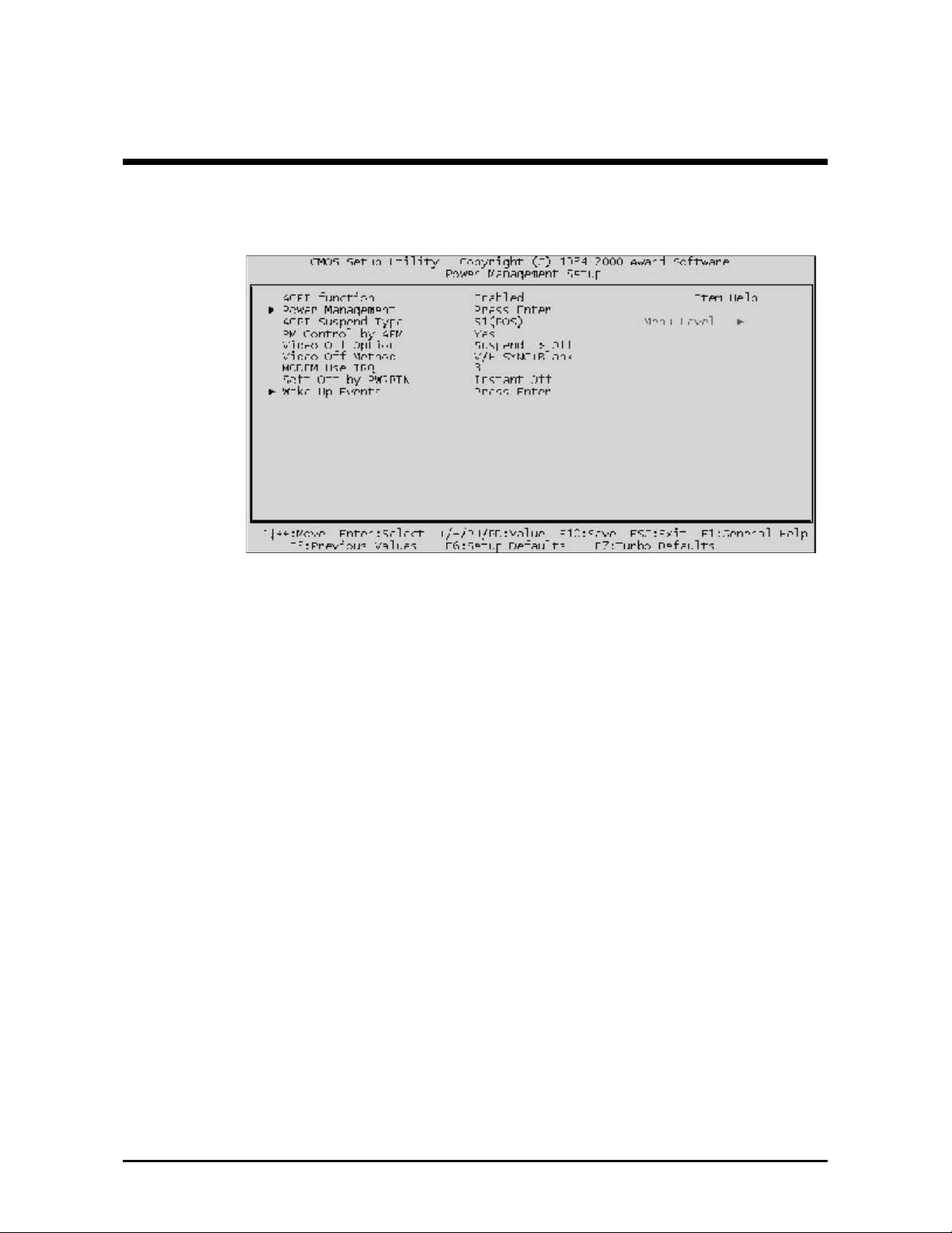
@@ Power Management Setup
The Power Management Setup allows you to configure the
motherboard green features.
ACPI Function
This item allows you to Enable/Disable the Advanced Configuration
and Power Management (ACPI)
Ø The choice: Enabled, Disabled.
Select "Power Management" to press "enter" key ,and then you
may run into the sub-menu. The sub-menu contains three items
listed as follows:
Power Management
This function allows you to set the default parameters of power-saving
modes. Set "User Define" to choose your own parameters or turn off the
power management function.
Ø The choice: User Define, Min Saving, Max Saving.
HDD Power Down
This option lets you specify the IDE HDD idle time before the device
enters power down state. This item is independent from the power
states previously described in this section (Standby and Suspend).
Ø The choice: Disable, 1Min, ....., 15Min.
- 65 -
Page 68

Doze Mode
This item lets you set the period of time after which the system enters
into Doze mode.
Ø The choice: 1Min, 2Min, 4Min, 6
Min, 8Min, 10Min, 20Min, 30Min,
40Min, 1Hour.
Press "Esc" key to go back to the previous sub-menu.
ACPI Suspend Type
This item allows you to select the ACPI suspend type. Select S3(STR) for
suspend to RAM or Select S1(POS) for power-on suspend under Windows 98 ACPI mode.
Ø The choice: S1(POS), S3(STR)
PM Control by APM
If this item is set to No, system BIOS will be ignored and APM calls the
power to manage the system.
If this item is set to Yes, system BIOS will wait for APM's prompt before it
enters any PM mode e.g. DOZE, STANDBY or SUSPEND.
Ø The choice: Yes, No.
Video Off Option
This item defines when to activate the video off feature for monitor
power management.
Ø The choice: Suspend, Doze, N/A.
Video Off Method
This determines the manner in which the monitor is blanked.
V/H SYNC + Blank This selection will cause the system to turn off
the vertical and horizontal synchronization ports and write blanks
to the video buffer.
Blank Screen This option only writes blanks to the video
buffer
DPMS Initial display power management signal.
Ø The choice: V/H SYNC + Blank, Blank Screen, DPMS Support.
Modem Use IRQ
This item determines the IRQ in which the MODEM can use.
Ø The choice: 3, 4, 5, 7, 9, 10, 11, N/A
- 66 -
Page 69

Soft-Off by PWRBTN
This is a specification of ACPI and supported by hardware. When
Delay 4 sec. is selected, the soft power switch on the front panel can be
used to control power On, Suspend and Off. If the switch is pressed less
than 4 sec during power On, the system will go into Suspend mode. If
the switch is pressed longer than 4 sec, the system will be turned Off.
The default setting is Install-Off, soft power switch is only used to control On and Off, there is no need to press 4 sec, and there is no Suspend.
Ø The choice: Instant-Off, Delay 4 Sec.
*** Wake Up Events ***
Wake Up Events can prevent the system from entering a power saving
mode or can awaken the system from such a mode. In effect, the system
remains alert for anything which occurs to a device which is configured
as On or Enabled, even when the system is in a power down mode.
Wake Up Events
This item allows user to determine the wake up events.
Ø The choice: Press "Enter" key to run into the sub-menu.
VGA
Set the item ON, while you wake up the system by LAN, and the VGA
is waken, too.
Ø The choice: ON, OFF.
LPT & COM
Set the item Enabled; users can awaken the system by any device
connected to LPT/COM ports.
Ø The choice: NON, LPT/COM, LPT, COM.
- 67 -
Page 70

HDD & FDD
Set the item ON; users can awaken the system by Hard Disk/Floppy
disk.
Ø The choice: ON, OFF.
PCI Master
Set the item ON; users can awaken the system by any PCI Card (Master
mode).
Ø The choice: ON, OFF.
Power On by PCI Card
Set the item Enabled; users can awaken the system by PCI card.
Ø The choice: Enabled, Disabled.
Modem Ring Resume
This option lets you enable or disable Wake On Modem function.
Ø The choice: Enabled, Disabled.
RTC Alarm Resume
Set the item Enabled, and then select the alarm time in the next few
items.
Ø The choice: Enabled, Disabled.
Date (of Month)
This is for specifying the alarm Date on which the system will
awaken the system from Suspend mode.
Ø The choice: Key in a DEC number: Min=0, Max=31.
Resume Time (hh:mm:ss)
This is for specifying the alarm Hour/Minute/Second on which
the system will awaken the system from Suspend mode.
Ø The choice: Key in a DEC number: Min=0, Max=23/59.
Primary INTR
Set the item Enabled; users can awaken the system by any device with
the IRQ designated by PCI Card.
Ø The choice: ON, OFF.
IRQs Activity Monitoring
Press "Enter" key to run into the sub-menu. You may enable any device
with listed IRQ to awaken the system.
Ø The choice: IRQ 3 ~ IRQ15.
- 68 -
Page 71

@@ PnP/PCI Configurations
The PnP/PCI Configurations allows you to configure the ISA and PCI
devices installed in your system.
PNP OS Installed
When this item is set to Yes, it will allow the PnP OS (Windows 95) to
control the system resources except PCI devices and PnP boot devices.
Default setting is No.
Ø The choice: Yes, No.
Reset Configuration Data
This item allows you to determine whether to reset the configuration
data or not.
Ø The choice: Enabled, Disabled.
Resources Controlled By
The Award Plug and Play BIOS has the capability to automatically
configure all of the boot and Plug and Play compatible devices. However, this capability means absolutely nothing unless you are using a
Plug and Play operating system as Windows 95.
Ø The choice: Auto, Manual.
- 69 -
Page 72

IRQ/DMA Resources
When resources are controlled manually, assign each system interrupt a
type. depending on the type of device using the interrupt.
IRQ3/4/5/7/9/10/11/12/14/15 assigned to
This item allows you to determine the IRQ assigned to the ISA bus and
is not available to any PCI slot. Legacy ISA for devices compliant with
the original PC AT bus specification, PCI/ISA PnP for devices compliant
with the Plug and Play standard whether designed for PCI or ISA bus
architecture.
Ø The choice: Reserved, PCI Device.
DMA 0/1/3/5/6/7 assigned to
These items allow you to determine the DMA assigned to the ISA bus
and is not available for PCI slot.
Ø The choice: Legacy ISA, PCI/ISA PnP.
PCI/VGA Pallete Snoop
It determines whether the MPEG ISA/VESA VGA Cards can work with
PCI/VGA or not. If you have MPEG ISA/VESA VGA Cards and PCI/VGA
Card worked, Enable this field. Otherwise, Please Disable it.
Ø The choice: Disabled, Enabled.
Assign IRQ for VGA
This item allows the user to set VGA IRQ Routing table Enabled or
Disabled.
Ø The choice: Enabled, Disabled.
Assign IRQ for USB
This item allows the user the option to assign an IRQ to onboard USB
controller. The onboard controller is always enabled, if no IRQ is
assigned to it, there will be a question mark report on the system device
under Windows 95/98.
Ø The choice: Enabled, Disabled.
- 70 -
Page 73
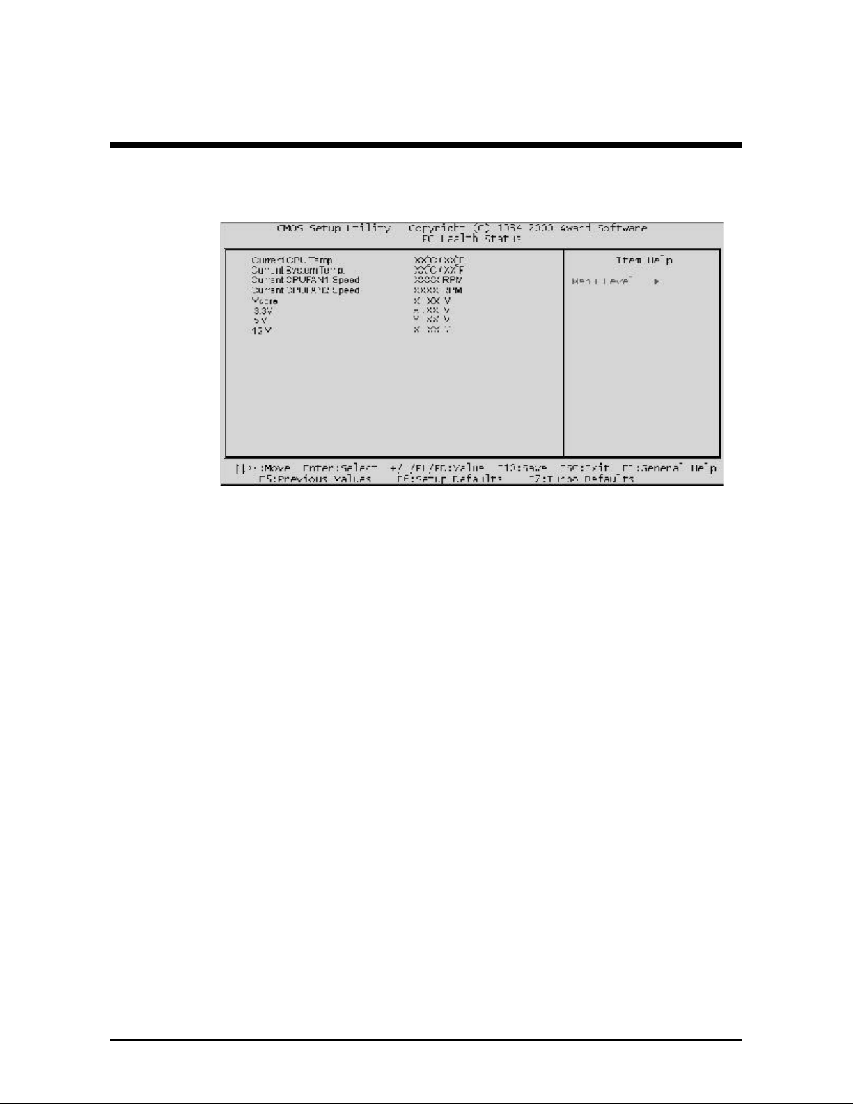
@@ PC Health Status
This submenu display hardware monitor status and provide some
basic control function. You can install VIA Hardware Monitoring
utility without using setup items in this submenu.
Current CPU Temperature
The mainboard supports CPU temperature monitoring and overheat
alert. This item indicates the current Processor temperature.
Current System Temp
The mainboard supports System Temperature monitoring and overheat
alert. This item indicate the current main board temperature.
Current CPUFAN1/2 Speed
The mainboard can detect two fans' rotation speed for CPU cooler.
Vcore
This mainboard supports CPU and mainboard voltages monitoring. The
onboard hardware monitor is able to detect the CPU voltage (Vcore)
and the voltage output from power supply.
3.3V, 5V, 12V
The mainboard supports CPU and mainboard voltages monitoring. The
onboard hardware monitor is able to detect the voltages output of the
voltage regulators and power supply.
- 71 -
Page 74

@@ Frequency/Voltage Control
Auto Detect DIMM/PCI Clk
This item allows you to enable/disable auto detection DIMM/PCI Clock.
CPU Host Clock (CPU/PCI)
The user may adjust the Host Clock of AMD socket A CPU.
- 72 -
Page 75

@@ Load Setup Defaults
The "Load Setup Defaults" option loads optimized settings for optimum
system performance. Optimal settings are relatively safer than the Turbo
settings. All the product verification, compatibility/reliability test
report and manufacture quality control are based on "Load Setup
Defaults". We recommend users to use this settings for normal opera-
tion. "Load Setup Defaults" is not the slowest setting for this
motherboard. If you need to verify an unstable problem, you may
manually set the parameter in the "Advanced BIOS Features" and
"Advanced Chipset Features" to get slowest and safer setting.
@@ Load Turbo Defaults
The "Load Turbo Defaults" option gives better performance than "Load
Setup Defaults". It is provided for the convenience of power user who
wants to push the motherboard to get better performance. Turbo setting
does not go through all the detail reliability and compatibility test, it is
tested only with limited configuration and loading (for example, a
system that contains only a VGA card and two DIMMs). Use Turbo
setting only when you fully understand the items in Chipset Setup
menu. The performance improvement of Turbo setting is normally
around 3% to 5%, depending on the chipset and the application.
- 73 -
Page 76
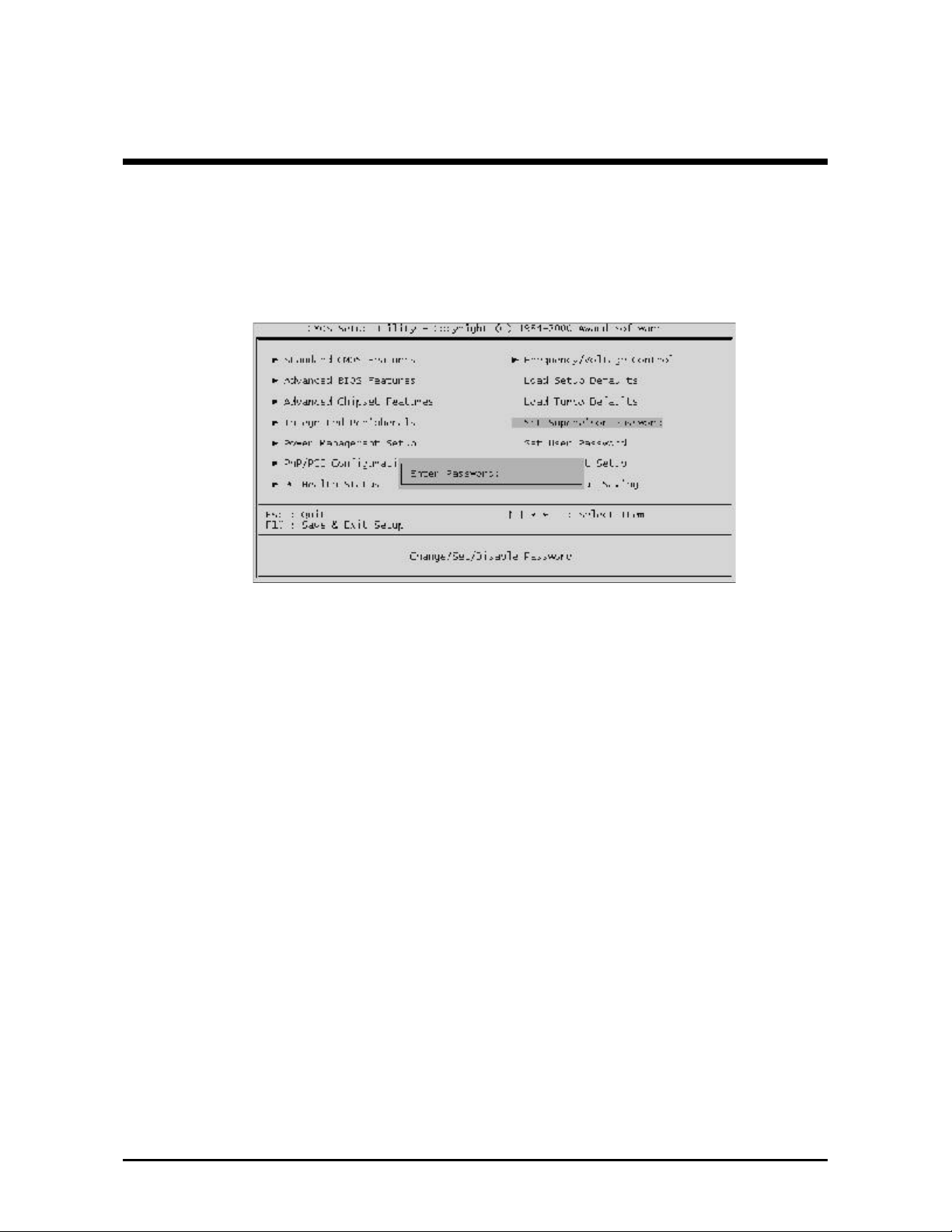
@@ User Password Setting
You can set either supervisor or user password or both of them. The
differences between them are:
Supervisor Password and User Setting
The options on the Password screen menu make it possible to restrict
access to the Setup program by enabling you to set passwords for two
different access modes: Supervisor mode and User mode.
In general, Supervisor mode has full access to the Setup option,
whereas User mode has restricted access to the option. By setting
separate Supervisor and User password, a system supervisor can limit
who will change critical Setup values.
Enter Password
Type the password up to eight characters, and press <Enter>. The
password typed now will clear any previously entered password from
CMOS memory. You will be asked to confirm the password. Type the
password again and press <Enter>. You may also press <Esc> to
abort the selection and not enter a password.
To disable password, just press <Enter> when you are prompted to
enter password. A message will confirm the password being disabled.
Once the password is disabled, the system will boot and you can enter
Setup freely.
- 74 -
Page 77

Password Disable
If you select System at Security Option of BIOS Features Setup Menu,
you will be prompted the password whenever the system is rebooted or
whenever you try to enter Setup. If you select Setup at Security Option
of BIOS Features Setup Menu, you will be prompted only when you try
to enter Setup.
Warning : Retain a record of your password in a safe place. If you
forget the password, the only way to access the system is
to clear CMOS memory, please refer to "Clear
CMOS" on page 29.
- 75 -
Page 78

@@ Save & Exit Setup
Press <Enter> on this item, and a similar dialog box shows up to ask
you the following confirmation :
Save to CMOS and EXIT (Y/N)? Y
Pressing "Y" stores the selections made in the menus of CMOS - a
special section of memory that stays on after you turn your system off.
When next time you boot your computer, the BIOS configures your
system according to the Setup selections stored in CMOS. After saving
the values, the system restarts again.
@@ Exit Without Saving
Press <Enter> on this item and a similar dialog box shows up to ask
you the following confirmation :
Quit without saving (Y/N)? Y
This allows you to exit from Setup without storing in CMOS any
change. The previous selections remain in effect. This exits from the
Setup utility and restarts your computer.
- 76 -
 Loading...