

Page 1

AB30/AB30R
Pentium 4 Processor
Based MAIN BOARD
User's Manual
Page 2

Shuttle® SpacewalkerTM AB30/AB30R
Pentium 4 , 478-pin processor based AGPset Mainboard
Manual Version 1.0
Copyright
Copyright© 2001 by Shuttle® Inc. All Rights Reserved.
No part of this publication may be reproduced, transcribed, stored in a retrieval system,
translated into any language, or transmitted in any form or by any means, electronic,
mechanical, magnetic, optical, chemical, photocopying, manual, or otherwise, without
prior written permission from Shuttle
Shuttle® Inc. shall not be liable for any incidental or consequential damages resulting from the
performance or use of this product.
This company makes no representations or warranties regarding the contents of this manual.
Information in this manual has been carefully checked for reliability; however, no guarantee is
given as to the correctness of the contents. In the interest of continued product improvement,
this company reserves the right to revise the manual or include changes in the specifications
of the product described within it at any time without notice and without obligation to notify any
person of such revision or changes. The information contained in this manual is provided for
general use by the customers.
®
Inc.
Disclaimer
Trademarks
Spacewalker is a registered trademark of Shuttle Inc.
Intel, Pentium is a registered trademarks of Intel Corporation.
PS/2 is a registered trademark of IBM Corporation.
AW ARD is a registered trademark of Award Software Inc.
Microsoft and Windows are registered trademarks of Microsoft Corporation.
General Notice: Other brand and product names used herein are for identification
purposes only and may be trademarks of their respective owners.
M474
Page 3

T ABLE OF CONTENTS
WHAT’S IN THE MANUAL.....................................................................5
Quick Reference................................................................................................5
About This Manual ............................................................................................5
1 INTRODUCTION ................................................................................. 6
1.1 TO DIFFERENT USERS ..............................................................................6
FIRST-TIME DIY SYSTEM BUILDER ............................................................ 6
EXPERIENCED DIY USER .........................................................................6
SYSTEM INTEGRA TOR ...............................................................................6
1.2 ITEM CHECKLIST:.......................................................................................7
2 FEATURES .......................................................................................... 8
2.1 SPECIFICATIONS ........................................................................................8
3 HARDWARE INSTALLATION ...........................................................11
3.1 STEP BY STEP INSTALLATION................................................................11
Accessories of AB30/AB30R ................................................................11
STEP 1 Install the CPU...........................................................................12
STEP 2 Set Jumpers..............................................................................14
STEP 3 Install SDRAM System Memory.................................................14
STEP 4 Install Peripherals in System Case.............................................15
STEP 5 Mount the Mainboard on the Computer Chassis ........................16
STEP 6 Connect Front Panel Switches/LEDs/Speaker/USB ..................17
STEP 7 Connect IDE, IDE RAID, and Floppy Disk Drives.......................19
STEP 8 Connect Other Internal Peripherals ............................................20
STEP 9 Connect the Power Supply ........................................................21
STEP 10 Install Add-on Cards in Expansion Slots ..................................21
STEP 11 Connect External Peripherals to Back Panel...........................22
STEP 12 First Time System Boot Up......................................................24
- 1 -
Page 4

STEP 13 Install Drivers & Software Components....................................25
3.2 JUMPER SETTINGS ..................................................................................26
JUMPERS & CONNECTORS GUIDE ....................................................27
Jumpers
Clear CMOS Setting (JP1) ....................................................................30
On board RAID Enable/Disable Setting (JP17) (AB30R only) .................31
FSB Speed Contiguration Setting (JP2).................................................32
Back-Panel Connectors
PS/2 Keyboard & PS/2 Mouse Connectors ............................................33
USB1/USB2 Port Connectors.................................................................33
COM1/2 Port Connectors .......................................................................33
Parallel Port Connector...........................................................................33
Line-Out (Front-Out) Port Connector .......................................................34
Line-In (Rear-Out) Port Connector...........................................................34
Mic-In Port Connector .............................................................................34
MIDI/GAME Port Connector....................................................................34
Front-Panel Connectors
A TX Power On/Off Switch Connector (PWON)........................................35
System Management Interface Connector (EPMI) ...................................35
Green LED Connector (GLED)...............................................................36
HDD LED Connector (HLED).................................................................36
Power LED Connector (PLED)...............................................................36
Hardware Reset Connector (RST) ..........................................................37
Keylock Connector (KEYLOCK) .............................................................37
Speaker Connector (SPEAKER)............................................................37
Extended USB Header (JP4)..................................................................38
- 2 -
Page 5

Internal Peripherals Connectors
Enhanced IDE, IDE RAID, and Floppy Connector ...................................39
Other Connectors
ATX Power Supply Connector (CN7, JP12, and JP13) ...........................40
Cooling Fan Connectors for CPU (FAN1), AGP (F AN2), chipset (F AN3),
System (FAN4).......................................................................................41
IR Header (JP16) ...................................................................................41
Audio CD-IN Connector (CN5) (Black)....................................................42
Audio Auxiliary-IN Connector (CN4) (White) ............................................42
Audio Bass/Center-Out Header (JP18)...................................................42
Wake-on Lan Connector (JP3)................................................................43
Smart Card Header (JP15) ....................................................................43
3.3 SYSTEM MEMORY CONFIGURATION ......................................................44
1. INST ALL MEMORY.............................................................................44
2. UPGRADE MEMORY.........................................................................44
4 SOFTWARE UTILITY .......................................................................45
4.1 Mainboard CD Overview ..........................................................................45
4.2 Install Mainboard Software ......................................................................46
4.2.A Install Chipset System Driver ............................................................47
4.2.B Install IDE Driver ...............................................................................48
4.2.C Install Audio Driver............................................................................49
4.2.D Install IDE RAID Driver (AB30R only) ................................................50
4.3 View the User's Manual............................................................................51
- 3 -
Page 6

5 BIOS SETUP.....................................................................................5 2
5.1 ENTER BIOS ..............................................................................................52
5.2 THE MAIN MENU .......................................................................................53
ST ANDARD CMOS FEATURES ................................................................55
ADVANCED BIOS FEATURES..................................................................59
ADVANCED CHIPSET FEATURES ...........................................................63
INTEGRATED PERIPHERALS...................................................................66
POWER MANAGEMENT SETUP ..............................................................70
PNP/PCI CONFIGURA TION .......................................................................74
PC HEALTH STA TUS.................................................................................76
FREQUENCY/VOL TAGE CONTROL..........................................................78
LOAD FAIL-SAFE DEFAULTS...................................................................79
LOAD OPTIMIZED DEFAU L TS ..................................................................79
SET SUPERVISOR P ASSWORD ..............................................................80
SET USER PASSWORD ...........................................................................80
SAVE & EXIT SETUP.................................................................................82
EXIT WITHOUT SA VING .............................................................................82
- 4 -
Page 7

WHAT’S IN THE MANUAL
Quick Reference
Hardware Installation >> Step-by-Step ................................................ Page 11
Jumper Settings >> A Closer Look ...................................................... Page 26
Drivers/Software Utilities >> How to Install ......................................... Page 45
BIOS Setup >> How to Configure ........................................................ Page 52
About This Manual
For First-Time DIY System Builder......................................................... Page 6
For Experienced DIY User ...................................................................... Page 6
For System Integrator ............................................................................. Page 6
- 5 -
Page 8

1 INTRODUCTION
1.1 To Different Users
First-Time DIY System Builder
Welcome to the DIY world! Building your own computer system is not as
difficult as you may think. To make your first computer DIY experience
successful, right from the start, we have designed the 3.1 Hardware Installation
section in a step-by-step fashion for all the first-time DIY system builders. Prior
to installation, we also suggest you to read the whole manual carefully to gain a
complete understanding of your new Shuttle AB30/AB30R mainboard.
Experienced DIY User
Congratulate on your purchase of the Shuttle AB30/AB30R mainboard. You
will find that installing your new Shuttle AB30/AB30R mainboard is just easy.
Bundled with an array of onboard functions, the highly-integrated AB30/AB30R
mainboard provides you with a total solution to build the most stable and reliable system. Refer to sections 3.2 Jumper Settings and Chapter 4 Drivers/
Software Utilities to find out how to get the best out of your new mainboard.
Chapter 5 BIOS Setup also contains the relevant information on how to tune
up your system to achieve higher performance.
System Integrator
You have wisely chosen Shuttle AB30/AB30R to construct your system.
Shuttle AB30/AB30R incorporates all the state-of-the-art technology of the
Brookdale chipset from Intel. It integrates the most advanced functions you
can find to date in a compact ATX board.
This manual adopted in AB30 and AB30R mainboards at the same time.
The difference between AB30 and AB30R is that AB30R equips with
onboard IDE RAID Controller. In the manual, if there are some standards,
characters, equipment or software only appeared or adopted by AB30R; it
will be mentioned (AB30R only)
- 6 -
Page 9
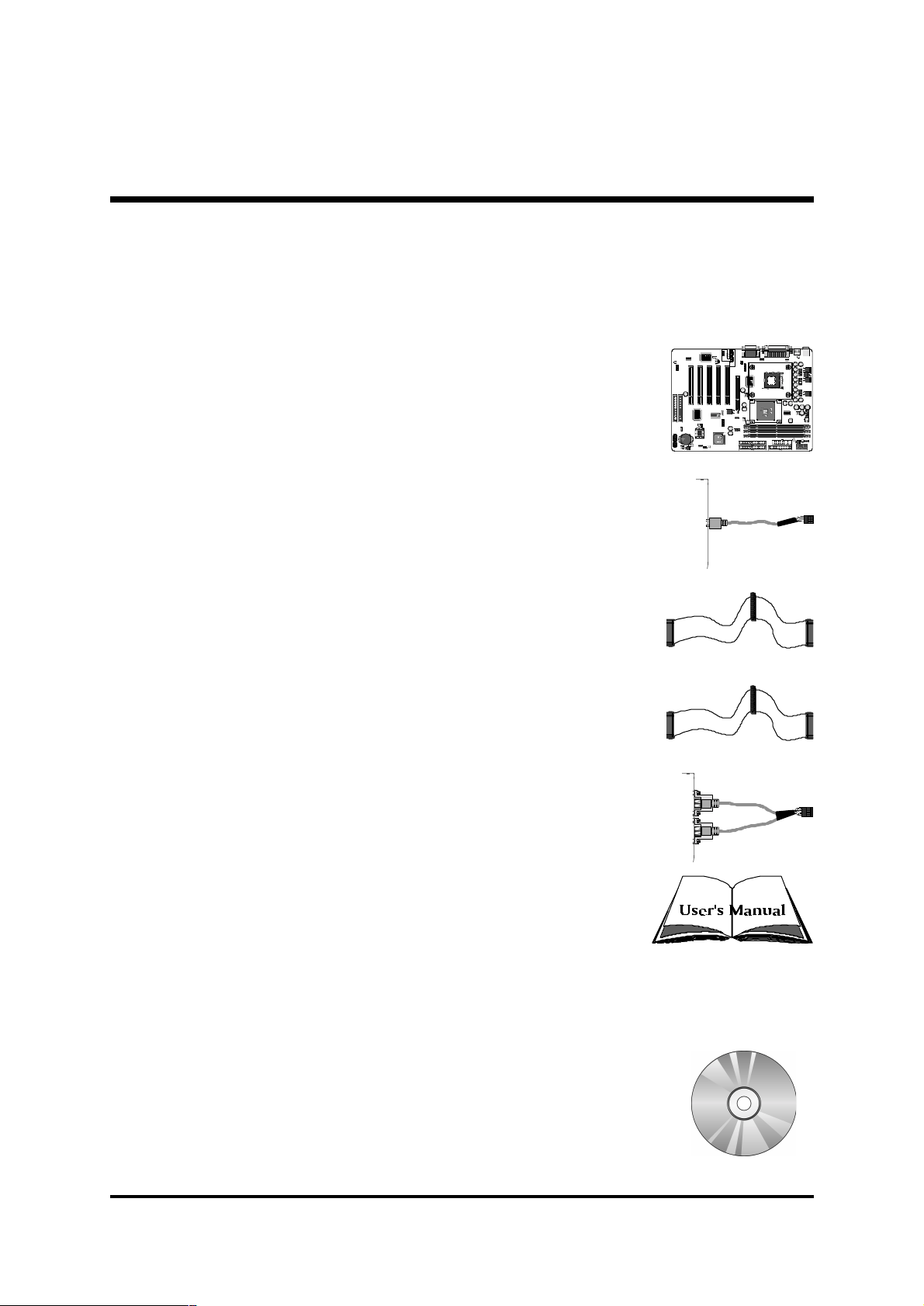
1.2 Item Checklist:
KB_MS
USB
COM1
COM2 PRT
AUDIO
ATX PWR
ATX12V
AUX_IN
CD-IN
WOL
BASS
PCI1
AGP
PCI2
PCI3
PCI4
PCI5
Check all items with you AB30/AB30R mainboard to make sure nothing is
missing. The complete package should include:
One piece of Shuttle AB30/AB30R Mainboard
One piece of Audio Cable (Central/Bass Channel)
One piece of ATA 100/66/33 Ribbon Cable
One piece of Floppy Ribbon Cable
JP18
CN4
1
11
C
MI8738/P
CI
-6c
h-LX
H
RT
F 3D A
ud
io
M
U
CX
GG
58.02-01
DA
10
JP16
1
1
JP4
RAID1
RAID2
1
1
JP3
JP14
EPMIRSTSPEAKER
+
CR2032
Panasonic
PWONPLEDKEYLOCK
-
GLED
HLED
+
+
-
1
F
AN3
CN5
Smart Reader
JP15
1
IT8712F-A
9944-DXS
MA4500
FAN2
1
2845
22 ES
3
RG8
E
S
1
5
F
I
A
2
0
0
2
0
5
9
2
M
3
1
0
-
0
1
0
0
0
S
-
E
C
1
0
O
J
U
2
R
PDC20265R
c
P
JP17
1
0Q
C
3V
A
JAPAN1
JP1
1
QC
9
C
3
.
4
1
FAN4
1
JP2
1
DIMM3DIMM2DIMM1
K
OR
EA
INTEL
QB73ES
V
102
TABQ
FW82801B
SEC
RE
T
IDE2
IDE1
11
1
FAN1
JP13
CN7
FDC
FLP1
1
J
P1
2
AUX PWR
One piece of twin ports USB Cable (optional)
AB30/AB30R Users Manual
One piece of Bundled CD-ROM with containing:
Ø AB30/AB30R users manual saved in PDF format
Ø IDE RAID users manual saved in PDF format (AB30R only)
Ø Intel Chipset System Driver
Ø Onboard Audio controller driver
Ø IDE driver
Ø IDE RAID driver (AB30R only)
Ø Award Flashing Utility
- 7 -
Page 10

2 FEA TURES
AB30/AB30R mainboard is carefully designed for the demanding PC user who wants
high performance and maximum intelligent features in a compact package.
2.1 Specifications
CPU Support
Intel Pentium 4, 478-pin processors with 100 MHz FSB.
Chipset
Features Intel 82845 N.B. and Intel 82801BA S.B..
Jumperless CPU Configuration
Soft-configuration FSB (The FSB speed is software configurable from 100MHz
to 166MHz by 1MHz step in the Frequency/Voltage Control of BIOS setup
program.)
On Board Multi-Channel Hardware Audio Controller
Support 5.1 speakers, C3DX positional audio in 6 CH speaker mode.
HRTF-3D positional audio, supporting Direct Sound 3D and A3D interface.
Legacy SBPRO compatible.
On Board IDE RAID Controller (AB30R only)
Support RAID 0, RAID 1 function.
Versatile Memory Support
Three 168-pin DIMM slots to support up to 3GB of PC100 or PC133 compliant
SDRAM.
PCI Expansion Slots
Provides five 32-bit PCI slots.
AGP Expansion Slots
Provides one 32-bit AGP slot which supports up to 4X AGP devices.
4 USB Interface Onboard
Ø 2 × USB connectors on back-panel and one sets of dual USB ports headers
on mid-board.
- 8 -
Page 11

I/O Interface
Provides a variety of I/O interfaces:
Ø 1 × Floppy interface for 3.5-inch FDD with 720KB, 1.44MB, or 2.88MB
format or for 5.25-inch FDD with 360K or 1.2MB format.
Ø 1 × PS/2 mouse connector.
Ø 1 × PS/2 Keyboard connector.
Ø 2 × DB9 Serial connectors 16550 UART compatible.
Ø 1 × Infrared communication port.
(Serial port COM2 can also be redirected to an external IrDA Adapter
for wireless connection.)
Ø 1 × DB25 Parallel port supports Standard Parallel Port and Bi-directional
(SPP), Enhanced Parallel Port (EPP), and Extended Capabilities Port (ECP)
data transmission schemes.
Ø 1 × Line-Out (Front-Out) port.
Ø 1 × Line-In port, shared with rear speaker output when multi-channel
audio is enabled.
Ø 1 × Mic-In port.
Ø 1 × MIDI/GAME port.
PCI Bus Master IDE Controller Onboard
Two Ultra DMA 100/66/33 Bus Master Dual-channel IDE ports provide support to a maximum of four IDE devices (one Master and one Slave per channel).
The IDE Bus implements data transfer speeds of up to 100/66/33 MB/sec and
also supports Enhanced PIO Modes.
80-pin Cable Backward Compatible Legacy ATAPI Devices, ATAPI IDE CDROM, CD-R, CD-RW, and LS-120 Supports.
ATX Power Supply Connector
ATX power supply unit can connected to the onboard 20-pin Pentium 4
standard ATX power connectors, supporting Suspend and Soft-On/Off by
dual-function power button.
The Pentium 4 ATX power include three connectors.
Advanced Configuration and Power Interface
Features four power saving modes: S1 (Snoop), S3 (Suspend to RAM), and S5
(Soft-Off). ACPI provides more efficient Energy Saving Features controlled by
your operating system that supports OS Direct Power Management (OSPM)
functionality.
- 9 -
Page 12

System BIOS
Provides licensed Award BIOS V6.0 PG on Intel Firmware Hub 4Mb Flash
core and supports Green PC, Desktop Management Interface (DMI).
ATX Form Factor
System board conforms to ATX specification.
Board dimension: 305mm × 220mm.
Advanced Features
Ø Low EMI - Built in spread spectrum and automatic clock shut-off of
unused PCI/SDRAMS slots to reduce EMI.
Ø Dual Function Power Button - The system can be in one of two states,
one is Suspend mode and the other is Soft-Off mode. Pushing the power
button for less than 4 seconds places the system into Suspend mode.
When the power button is pressed for longer than 4 seconds, the system
enters Soft-Off mode.
Ø Modem Ring Power-On - The system can be powered on automatically by
the activation of modem ringing.
Ø CPU Clock Setting - This item allows users to adjust CPU Host Clock in
BIOS.
Ø CPU Multiplier Setting - This item allows users to adjust CPU Multiplier in
BIOS.
Ø CPU Vcore Setting - This item allows users to select the CPU Vcore in
BIOS.
Intelligent Features
Ø Voltage Monitoring - Monitors various voltages of key elements, such as
the CPU, and other critical system voltage levels to ensure stable current
passing through mainboard components. System voltages include
Voltage0~7, Voltage Battery on system etc.
Ø Fan Status Monitoring - To prevent CPU from overheating, the CPU fan is
monitored for RPM and failure. (CPU Cooling FAN with RPM sensor is
required.)
Ø Temperature Monitoring - This item allows users to make sure whether the
CPU or system runs in a suitable temperature.
- 10 -
Page 13

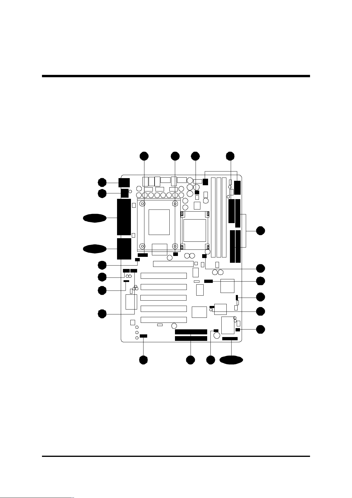
3 HARDWARE INSTALLA TION
Before removing or installing any of these devices including CPU, DIMMs, Add-On
Cards, Cables, please make sure to unplug the onboard power connector.
This section outlines how to install and configure your mainboard. Refer to the following
mainboard layout to help you to identify various jumpers, connectors, slots, and ports.
Then follow these steps designed to guide you through a quick and correct installation of
your system.
3.1 Step-by-Step Installation
Accessories Of AB30/AB30R
SOCKET 478
PS/2 Keyboard and
PS/2 Mouse Connectors
Two USB Connect ors
Seri al Port
Connector ( COM1)
Parall el Connect or
Seri al Port
Connector ( COM2)
I/O Contro ller
Line-Out/Line-In/Mic-In/
Game/MIDI Connec tors
Smar t Card Reader
Connector - JP1 5
IR Connector - JP1 6
Onboard Audio
Connectors- CN4/CN5/
JP18
Five PCI Sl ots
On Board Mul ti-Channe l
Hardware Audio Controller
Exte nded USB 1.1
Headers - J P4
INTEL 82845 Chipse t
KB_MS
USB
COM1
COM2 PRT
IT8712F-A
9944-DXS
MA4500
1
PCI1
PCI2
PCI3
PCI4
PCI5
JP4
1
FAN2
AGP
RAID1
RAID2
AUX_IN
CN4
BASS
JP18
AUDIO
JP16
1
CN5
CD-IN
CMI8738/PC I-6ch-LX
HRTF 3D Audio
MCX58.02-0110
UGGDA
1
JP15
Smart Reader
Two RAID C onnectors (AB30R only)
On Board Promise 20265R IDE RAID
Controll er (AB30R only)
On Board RAID Enable/Disable (AB30R only)Connector - JP17
ATX 12V Power Conne ctor
ATX12V
JP13
1
FAN1
Three DIMM Slot s
ATX PWR
CN7
AUX PW R
JP12
FDC
FLP1
Floppy C onnectorTwo E-IDE Connectors
1
FAN1FAN2
QC 22 ES
RG8 2845
ATX AUX Power Connector
1
FAN4
14.3C93
UJ01C-ES
01132
950202AF
2000-0051
c
PDC2026 5R
PROMISE
1
1
DIMM3DIMM2DIMM1
JP2
KOREA
INTEL 0Q
C
1
JP17
JP3
WOL
JP14
11
FAN4 ATX Power Connector
IDE2
IDE1
SECRET
FW82801BA
V102TABQ
QB 73ES
JP111
JAPAN1
3V
CR2032
Panasonic
1
FAN3
HLED
EPMI RSTSPEAKER
+
-
++-
GLED
PWONPLEDKEYLOCK
One AGP 4x Slot
Clock Generator
Clear CMOS - JP1
INTEL 82801BA Chipse t
FSB Sele cta ble Header - JP2
FAN3
Front-Pane l Connector - JP 14
Wake on LAN - JP3
Prog ramma ble Flash EEPROM (FWH)
- 11 -
Page 14

Step 1
CPU Installation:
This mainboard supports Intel ® Pentium ® 4 , Socket 478 series CPU. Please
follow the step as below to finish CPU installation.
Be careful of CPU orientation when you plug it into CPU socket.
1. Pull up the CPU socket level and up to 90-degree angle.
CPU socket level up to
90 degree
2. Locate Pin 1 in the socket and look for a black dot or cut edge on the CPU
upper interface. Match Pin 1 and cut edge, then insert the CPU into the
socket.
CPU pin 1 and cut edge
- 12 -
Page 15
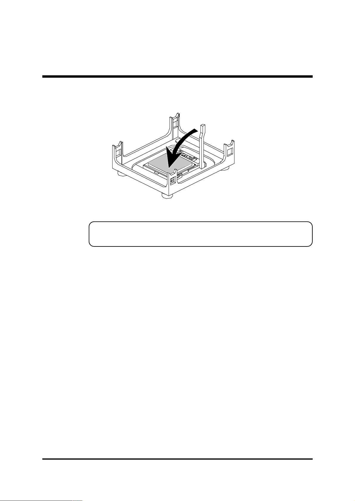
3. Press down the CPU socket level and finish CPU installation.
Note: If you do not match the CPU socket Pin 1 and CPU cut
edge well, it may damage the CPU.
- 13 -
Page 16

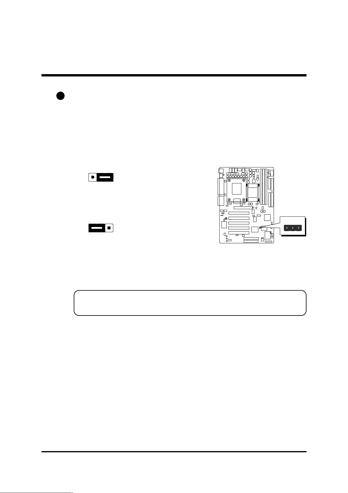
Step 2.
Set Jumpers
This mainboard is jumperless! The default jumper settings have been set for
the common usage standard of this mainboard. Therefore, you do not need
to reset the jumpers unless you require special adjustments as any of the
following cases:
1. Clear CMOS
2. Over Clock
For first-time DIY system builders, we recommend that you do not change the
default jumper settings if you are not totally familiar with the mainboard
configuration procedures. The factory-set default settings are tuned for optimum system performance. For the advanced users who wish to customize
their system, section 3.2 Jumper Settings will provide detailed information on
how to configure your mainboard manually.
Step 3
Install SDRAM System Memory
To install memory, insert SDRAM memory module(s) in any one or two or
three DIMM banks. Note that SDRAM modules are directional and will not
go in the DIMM slots if they are not properly oriented. After the module is
fully inserted into the DIMM slot, lift the clips of both sides of the DIMM bank
to lock the module in place.
- 14 -
Page 17

Step 4
Install Internal Peripherals in System Case
Before you install and connect the mainboard into your system case, we
recommend that you first assemble all the internal peripheral devices into the
computer housing, including but not limited to the hard disk drive (IDE/
HDD), floppy disk drive (FDD), CD-ROM drive, and ATX power supply unit.
This will greatly facilitate in making the connections to the mainboard described below.
To install IDE & FDD drives, follow this procedure:
1. Set the required jumpers on each device according to the instructions
provided by the manufacturer. (IDE devices, HDD, and CD-ROM, have to
set jumpers to Master or Slave mode depending on whether you install
more than one device of each kind.)
2. Connect IDE cable and FDD cable on the back-panel of the internal
peripheral devices to the corresponding headers on board. Note that the
cable should be oriented with its colored stripe (usually red or magenta)
connected to pin#1 both on the mainboard IDE or FDD connector and on
the device as well.
3. Connect an available power cable from your system power supply unit
to the back-panel of each peripheral device. Note that the power cable is
directional and cannot fit in if not properly positioned.
- 15 -
Page 18

Step 5
Mount the Mainboard on the Computer Chassis
1. You may find that there are a lot of different mounting hole positions
both on your computer chassis and on the mainboard. To choose
correct mounting holes, the key point is to keep the back-panel of the
mainboard in a close fit with your system case, as shown below.
2. After deciding on the proper mounting holes, position the studs between
the frame of the chassis and the mainboard. The studs are used to fix the
mainboard and to keep a certain distance between the system chassis
and the mainboard, in order to avoid any electrical shorts between the
board and the metal frame of the chassis. (If your computer case is
already equipped with mounting studs, you will need to tighten screws to
attach the mainboard.)
Note: In most computer housings, you will be able to find 4 or more
attachment points to install mounting studs and then fix the
mainboard. If there arent enough matching holes, then make sure to
install at least 4 mounting studs to ensure proper attachment of the
mainboard.
- 16 -
Page 19

Step 6
Connect Front Panel Switches/LEDs/Speaker/USB
You can find there are several different cables already existing in the system
case and originating from the computers front-panel devices (HDD LED,
Power LED, Reset Switch, PC Speaker, or USB devices etc.) These cables
serve to connect the front-panel switches, LEDs, and USB connectors to the
mainboards front-panel connectors group (JP14 and JP4), as shown below.
JP4
1
1. Hardware Reset Switch Button (RST)
2. HDD-LED (HLED)
JP 14
JP 14
JP14
SPEAKER
SPEAKER
EPMI RSTSPEAKER
-
EPMI
EPMI
HLED
+
-
PWON GLEDPLEDKEYLOCK
-++-
RST
HLED
+
-
-++-
RST
GLED
HLED
+
-
PWONPLEDKEYLOCK
-++
PWONPLEDKEYLOCK
GLED
3. Green-LED (GLED)
- 17 -
JP 14
SPEAKER
EPMI
RST
PWONPLEDKEYLOCK
HLED
+
-
-++-
GLED
Page 20
4. System Management Interface Button
(EPMI)
5. ATX Soft Power On/Off (PWON)
6. Power LED (PLED)
JP 14
JP 14
JP 14
SPEAKER
SPEAKER
EPMI
EPMI
EPMI
RST
PWONPLEDKEYLOCK
RST
PWONPLEDKEYLOCK
RSTSPEAKER
PWONPLEDKEYLOCK
HLED
+
-
-++-
GLED
HLED
+
-
-++-
GLED
HLED
+
-
-++-
GLED
7. Keylock (KEYLOCK)
8. PC Speaker (SPEAKER)
- 18 -
JP 14
JP 14
SPEAKER
EPMI
EPMI
RST
PWONPLEDKEYLOCK
RSTSPEAKER
PWONPLEDKEYLOCK
HLED
+
-
-++-
GLED
HLED
+
-
-++-
GLED
Page 21

9. Extended USB Header
+5V
1
USB port 4
U SBD 1-
U SBD 1+
GND
OC0
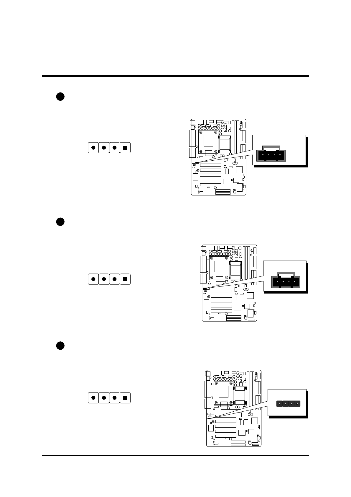
Step 7
Connect IDE, IDE RAID, and Floppy Disk Drives
1. IDE cable connector
2. IDE RAID cable connector (AB30R only)
+5V
U SBD 0-
GND
U SBD 0+
USB port 3
KEY
11
IDE1IDE2
- 19 -
RAID 1
RAID 2
1
1
Page 22

3. Floppy cable connector
Step 8
Connect Other Internal Peripherals
1. CD-IN , Auxiliary-IN, Bass/Center-Out connectors
FDC
FLP1
1
2. IR header
CN4
BASS
JP18
AU X_IN
11
CN5
CD-IN
1
JP1 6
1
- 20 -
Page 23

Step 9
Connect the Power Supply
1. System power connector
ATX12V
JP13
AUX PWR
JP12
ATX PWR
Step 10
Install Add-on Cards in Expansion Slots
1. Accelerated Graphics Port (AGP) Card
2. PCI Card
CN7
- 21 -
Page 24

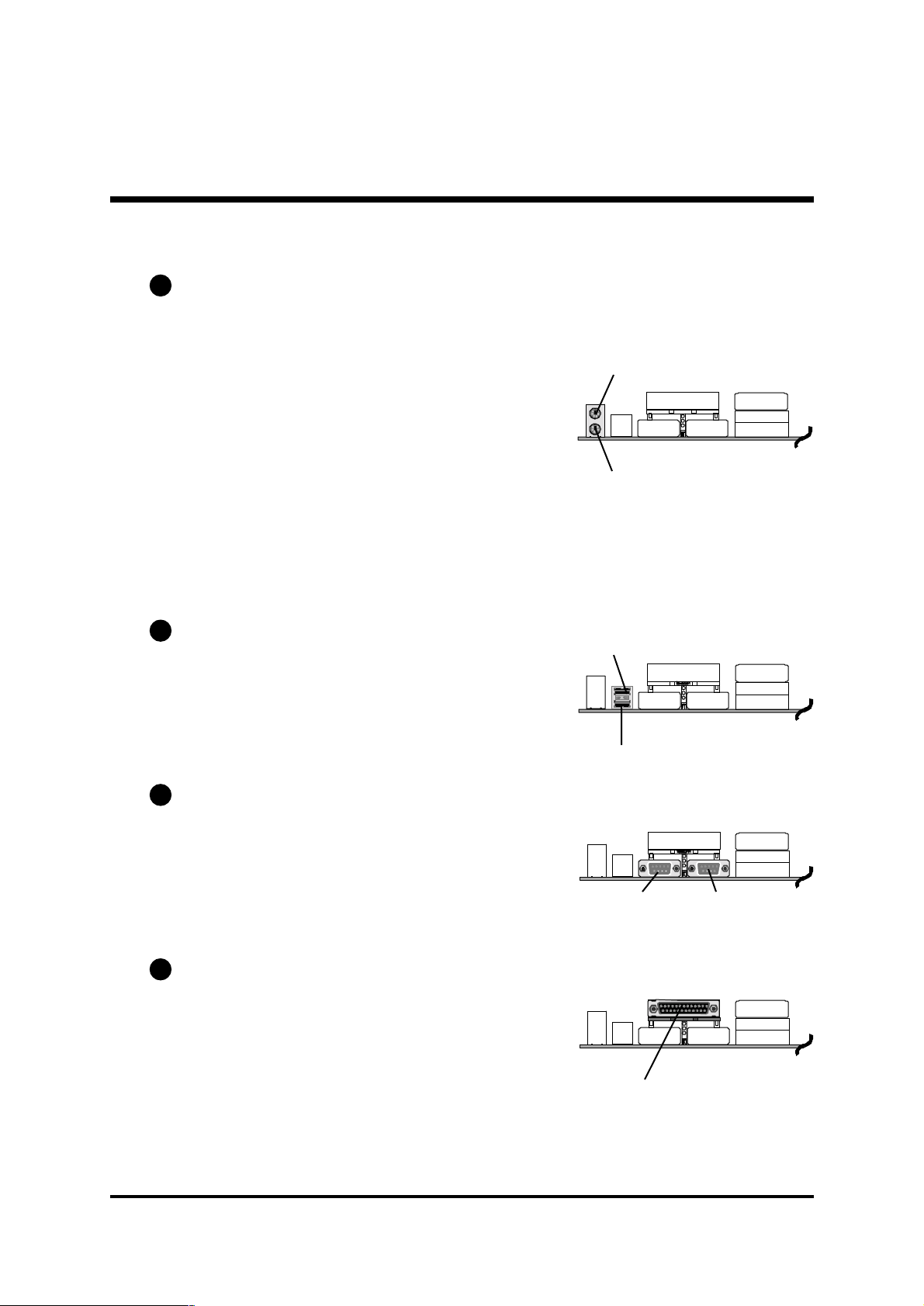
Step 11
Connect External Peripherals to Back-Panel
You are now ready to put the computer case back together and get on to the
external peripherals connections to your systems back-panel.
1. PS/2 Mouse and PS/2 Keyboard
PS/2 Mouse
KB_MS
US B
COM 1
COM2 PRT
AUDIO
2. USB Ports
3. COM Ports
PS/2 keyboard
USB Port 2
USB Port 1
COM1 Port COM2 Port
- 22 -
Page 25

4. Parallel Port
foxco nn
Parallel Port
5. MIDI/GAME Port
MIDI/GAME Port
6. Audio Line-Out (Front-Out) /Line-In (Rear-Out) / Mic-In Ports
Line-Out Port
(Front-Out)
Line-In Port
(Rear-Our)
Mic-In Port
- 23 -
Page 26

Step 12
First Time System Boot Up
To assure the completeness and correctness of your system installation, you
may check the above installation steps once again before you boot up your
system for the first time.
1. Insert a bootable system floppy disk (DOS 6.2x, Windows 95/98/NT, or
others) which contains FDISK and FORMAT utilities into the FDD.
2. Turn on the system power.
3. First, you must use the FDISK utility to create a primary partition of the
hard disk. You can also add an extended partition if your primary parti-
tion does not use all of the available hard disk space. If you choose to
add an extended partition, you will have to create one or more logical
partitions to occupy all the space available to the extended partition. The
FDISK utility will assign a drive letter (i.e., C:, D:, E:,...) to each partition
which will be shown in the FDISK program. After FDISK procedure,
reboot your system by using the same system floppy disk.
Note: DOS 6.2x and Windows 95A can only support up to 2.1GB of
HDD partition. If you use the FDISK utility with one of the operating systems mentioned above, you can only install your HDD into
partitions no larger than 2.1GB each.
4. Now, use the FORMAT utility to format all the partitions youve created.
When formatting the primary partition (C:), make sure to use the FORM-
AT C: /S command.
Note: FORMAT C: /S can transfer all the necessary system files into the
primary partition of your hard disk. Then, your HDD will become
a bootable drive.
5. Install all the necessary drivers for CD-ROM, Mouse, etc.
6. Setup the complete operating system according to your OS installation
guide.
- 24 -
Page 27

Step 13
Install Drivers & Software Components
Please note that all the system utilities and drivers are designed for Win 9x/
2000/ME/NT operating systems only. Make sure your operating system is
already installed before running the drivers installation CD-ROM programs.
1. Insert the AB30/AB30R bundled CD-ROM into your CD-ROM drive. The
auto-run program will display the drivers main installation window on
screen.
2. Select the "Install Mainboard Software" bar to run into sub-menu.
3. Choose "Install Chipset System Driver" and complete it.
4. Choose "Install Intel Ultra ATA Driver" and complete it.
5. Choose "Install Audio Driver" and complete it.
6. Choose "Install promise 20265R RAID Driver" bar to run readme
windows if you need install drivers. (AB30R only)
7. Return to the main installation window and exit from the auto-run drivers
installation program.
Note: Please refer to IDE Raid Manual to install IDE RAID
Controller driver when you purchase AB30R mainboard.
- 25 -
Page 28
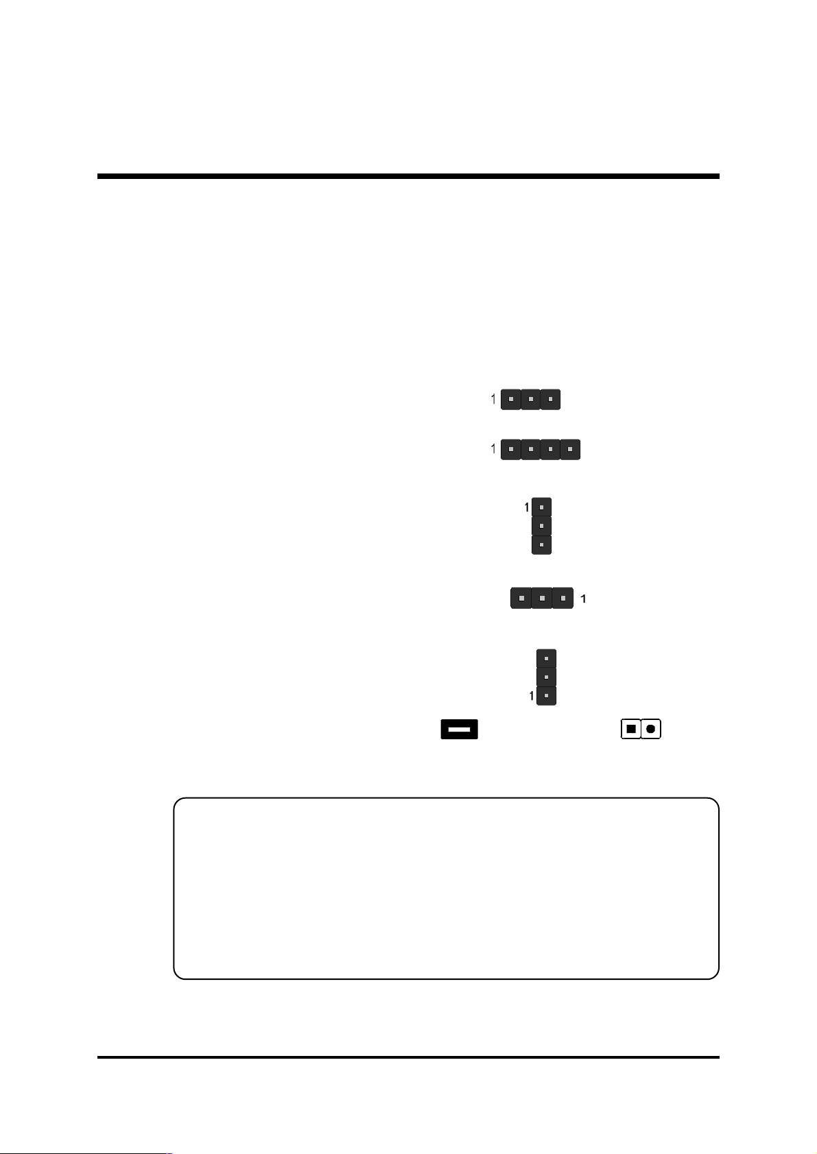
3.2 Jumper Settings
Several hardware settings are made through the use of mini jumpers to connect jumper pins on the mainboard. Pin #1 could be located at any corner
of each jumper, you just find the location with a white right angle which
stands for pin 1#. There are several types of pin 1# shown as below:
3-pin and multi (>3) pin jumpers shown as following:
Pin #1 to the left:
Pin #1 on the top:
Pin #1 to the right:
Pin #1 on the bottom:
Jumpers with two pins are shown as for Close [On] or for
Open [Off]. To Short jumper pins, simply place a plastic mini jumpers over
the desired pair of pins.
Caution!
1. Do not remove the mainboard from its antistatic protective packaging
until you are ready to install it.
2. Carefully hold the mainboard by its edges and avoid touching its
components. When putting the mainboard down, place it on top of its
original packaging film, on an even surface, and components side up.
3. Wear an antistatic wrist strap or take other suitable measures to prevent
electrostatic discharge (ESD) whenever handling this equipment.
- 26 -
Page 29
Jumpers & Connectors Guide
Use the mainboard layout on page 11 to locate CPU socket, memory banks,
expansion slots, jumpers and connectors on the mainboard during the installation. The following list will help you to identify jumpers, slots, and connectors along with their assigned functions:
B1
B2
B3~B4
B5~B8
E3
E5
E6
E4
E2E2E8
E1
D1
E2
A3
A1
A2
E2
C9
D1 E7
C1~C8
CPU/Memory/Expansion Slots
Socket478 : CPU Socket for Pentium 4 processors
DIMM1/2/3 : Three DIMM Slots for 16,32,64,128,256,512MB
and 1GB,3.3V SDRAM.
AGP : One AGP (Accelerated Graphics Port) Slot
PCI : Five 32-bit PCI Expansion Slots
- 27 -
Page 30

Jumpers
A1
A2
A3
JP1 : Clear CMOS setting
JP17 : On board RAID Enable/Disable setting (AB30R only)
JP2 : FSB Speed Configure setting
Back Panel Connectors
B1
B1
B2
B3
B4
B5
B6
B7
B8
KB : PS/2 keyboard port
MS : PS/2 mouse port
USB : 2 USB (Universal Serial Bus) ports
COM1/2 : Serial ports 1/2 (DB9 male)
PRINTER : Parallel port (DB25 female)
LINE_OUT : Line-Out (Front-Out) port
LINE_IN : Line-In (Rear-Out) port
MIC_IN : Mic-In port
GAME/MIDI : GAME/MIDI Port
Front Panel Connectors
C1
C2
C3
C4
C5
C6
C7
C8
C9
PWON : ATX power on/off momentary type switch
EPMI : System Management Interface
GLED : Green LED
HLED : IDE drive active LED
PLED : System power LED
RST : Hardware reset switch
KEYLOCK : KEYLOCK
SPEAKER : Internal speaker in housing
JP4 : Extended USB header
Internal Peripherals Connectors
D1
D1
D1
FLP1 : Floppy disk drive interface
IDE1 : IDE primary interface (Dual-channel)
IDE2 : IDE secondary interface (Dual-channel)
- 28 -
Page 31

D1
RAID1 : RAID primary interface (Dual-channel) (AB30R only)
D1
RAID2 : RAID secondary interface (Dual-channel) (AB30R only)
Other Connectors
E1
E2
E2
E2
E2
E3
E4
E5
E6
E7
E8
CN7/JP12/JP13 : ATX power connector
FAN1 : CPU fan connector
FAN2 : AGP fan connector
FAN3 : Chipset fan connector
FAN4 : System fan connector
JP16 : IR header
CN5 : CD_IN connector
CN4 : Auxiliary_IN connector
JP18 : Bass/Center_Out header
JP3 : Wake-On-LAN connector
JP15 : Smart Card header
- 29 -
Page 32

F Jumpers
A1
Clear CMOS Setting (JP1)
JP1 is used to clear CMOS data. Clearing CMOS will result in the permanently erasing previous system configuration settings and the restoring original (factory-set) system settings.
1
Pin 1-2 (Default)
1
Pin 2-3 (Clear CMOS)
Step 1. Turn off the system power (PC-> Off).
Step 2. Remove ATX Power cable from ATX Power connector.
Step 3. Remove jumper cap from JP1 pins 1-2.
Step 4. Place the jumper cap on JP1 pin 2-3 for a few seconds.
Step 5. Return the jumper cap to pin 1-2.
Step 6. Plug ATX Power cable into ATX Power connector.
Step 7. Turn on the system power (PC-> On).
JP1
1
- 30 -
Page 33
A2
On board RAID Enable/Disable Setting (JP17) (AB30R only)
JP17 is used to enable/disable IDE RAID controller.
You may choose to place jumper cap on pins 2-3 for enable IDE RAID
controller function; inserting jumper cap on pins 1-2 for disable IDE RAID
controller function.
1
To disable IDE RAID
function
Pin 1-2
1
To enable IDE RAID
function
Pin 2-3
Note: Please refer to IDE Raid Manual to check information about IDE
RAID Controller.
1JP17
- 31 -
Page 34

A3
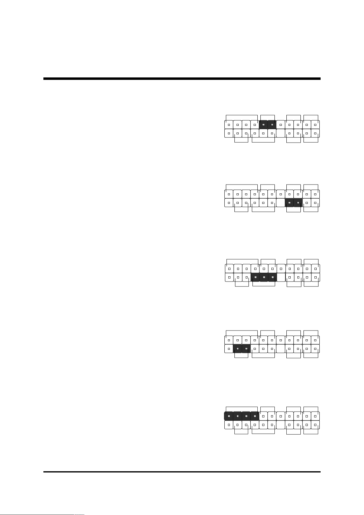
FSB Speed Configuration Setting (JP2)
AB30/AB30R provides jumper JP2 to configure front side bus at 100MHz, and
133MHz. Inserting mini-jumper caps on JP2 pin 11-12 to identify automatically
the FSB speed.
Default
11 9 7 5 3 1
Set FSB hardware
jumper to Auto.
12 10 8 6 4 2
For experienced users, AB30/AB30R mainboard provides an alternative
hardware configured function to adjust Front Side Bus manually. Please
insert mini jumpers properly on JP2 and set "PCI Clock" option in seb-menu
of "Frequency/Voltage Control" of BIOS setup program.
JP2
1
11 9 7 5 3 1
10 0 M H z 14 1M H z
12 10 8 6 4 2
11 9 7 5 3 1
10 9 M H z 15 0 M H z
12 10 8 6 4 2
11 9 7 5 3 1
12 0 M H z 16 0 M H z
12 10 8 6 4 2
11 9 7 5 3 1
13 3 M H z 17 0 M H z
12 10 8 6 4 2
11 9 7 5 3 1
12 10 8 6 4 2
11 9 7 5 3 1
12 10 8 6 4 2
11 9 7 5 3 1
12 10 8 6 4 2
11 9 7 5 3 1
12 10 8 6 4 2
- 32 -
Page 35
F Back-Panel Connectors
B1
PS/2 Keyboard & PS/2 Mouse Connectors
Two 6-pin female PS/2 keyboard & Mouse
connectors are located at the rear panel of
the mainboard. Depending on the computer housing you use (desktop or tower),
the PS/2 Mouse connector is situated at the
top of the PS/2 Keyboard connector when
the mainboard is laid into a desktop, as opposed to a tower where the PS/2 Mouse
connector is located at the right of the PS/2
Keyboard's. Plug the PS/2 keyboard and
mouse jacks into their corresponding connectors.
B2
USB1/USB2 Port Connectors
This mainboard offers 2 USB ports on front
panel. Plug each USB device jack into an
available USB1/USB2 connector.
PS/2 Mouse
PS/2 keyboard
USB Port 2
B3
COM1/2 Port Connectors
This mainboard can accommodate two
serial device on COM1/2. Attach a serial
device cable to the DB9 serial port COM1/
2 at the back panel of your computer.
B4
Parallel Port Connector
One DB25 female parallel connector is located at the rear panel of the mainboard.
Plug the connection cable from your parallel device (printer, scanner, etc.) into this
connector.
USB Port 1
COM1 Port COM2 Port
foxcon n
Parallel Port
- 33 -
Page 36

B5
Line-Out (Front-Out) Port Connector
Line-Out is a stereo output port through which
the combined signal of all internal and external audio sources on the board is output. It
can be connected to 1/8-inch TRS stereo
headphones or to amplified speakers
B6
Line-In (Rear-Out) Port Connector
Line-In is a stereo line-level input port that
accepts a 1/8-inch TRS stereo plug. It can be
used as a source for digital sound recording,
a source to be mixed with the output, or both.
B7
Mic-In Port Connector
Mic-In is a 1/8-inch jack that provides a mono
input. It can use a dynamic mono or stereo
microphone with a resistance of not more than
600 Ohms.
Line-Out (Front-Out)
Line-In (Rear-Out)
B8
MIDI/GAME Port Connector
The MIDI/GAME port is a 15-pin female connector. This port can be connected to any
IBM PC compatible game with a 15-pin Dsub connector.
MIDI Instrument Connection
You will need a MIDI adapter to connect a MIDI compatible instrument
to the sound card. The MIDI adapter can in turn be connected to the
Joystick/MIDI port. You will also need the MIDI sequencing software to
run MIDI instruments with your computer etc. into this connector.
Mic-in
MIDI/GAME Port
- 34 -
Page 37

F Front-Panel Connectors
C1
ATX Power On/Off Switch Connector (PWON)
The Power On/Off Switch is a momentary type switch used for turning on or off
the system ATX power supply. Attach the connector cable from the Power
Switch to the 2-pin PWON header on the mainboard.
Note : Please notice all the LED connectors are directional. If your chassiss
LED does not light up during running, please simply change to the
opposite direction.
C2
EPMI Connector (EPMI)
Hardware System Management Interface (EPMI) header may attach to 2-pin
momentary switch. Press the switch to force system into power saving mode;
press it again to resume back the normal operation situation.
JP14
EPMI RSTSPEAKER
HLED
+
-
-++-
GLED
PWONPLEDKEYLOCK
- 35 -
JP14
SPEAKER
EPMI
PWONPLEDKEYLOCK
RST
HLED
+
-
-++-
GLED
Page 38

Green LED Connector (GLED )
C3
The Green LED (GLED) indicates that the system is currently in one of the power
saving mode (Doze/Standby/Suspend). When the system resumes to normal
operation mode, the Green LED will go off. Attach a 2-pin Green LED cable to
GLED header.
C4
HDD LED Connector (HLED)
Attach the connector cable from the IDE device LED to the 2-pin HLED header.
The HDD LED lights up whenever an IDE device is active.
C5
Power LED Connector (PLED)
JP14
JP14
EPMI RSTSPEAKER
-
EPMI RSTSPEAKER
-
HLED
+
-
-++
GLED
PWONPLEDKEYLOCK
HLED
+
-
-++
GLED
PWONPLEDKEYLOCK
Attach the 3-pin Power LED connector cable from the housing front panel to
the PLED header on the mainboard. The power LED stays light while the system is on.
EPMI RSTSPEAKER
JP14
HLED
+
-
-++-
GLED
PWONPLEDKEYLOCK
- 36 -
Page 39

Hardware Reset Connector (RST)
C6
Attach the 2-pin hardware reset switch cable to the RST header. Pressing the
reset switch causes the system to restart.
C7
Keylock Connector (KEYLOCK)
Attach the 2-pin KEYLOCK connector cable from the housing front panel to the
KEYLOCK header on the mainboard.
JP14
JP14
EPMI RSTSPEAKER
EPMI RSTSPEAKER
HLED
+
-
-++-
GLED
PWONPLEDKEYLOCK
HLED
+
-
-++-
GLED
PWONPLEDKEYLOCK
C8
Speaker Connector (SPEAKER)
Attach the PC speaker cable from the case to the 4-pin speaker connector
(SPEAKER).
- 37 -
JP14
SPEAKER
EPMI
PWONPLEDKEYLOCK
RST
HLED
-
-++-
GLED
+
Page 40

C9
Extended USB Header (JP4)
The headers are used to connect the cable attached to USB connectors
which are mounted on front panel or back panel. But the USB cable is optional at the time of purchase.
USB port 4
2 4 6 8 10
1 3 5 7 9
USB port 3
Pins Assignment:
1=+5V
3=USBD05=USBD0+
7=GND
9=KEY
2=+5V
4=USBD16=USBD1+
8=GND
10=OC0
JP4
1
- 38 -
Page 41

F Internal Peripherals Connectors
D1
Enhanced IDE, IDE RAID (AB30R only), and Floppy
Connectors
The mainboard features two 40-pin dual-channel IDE device connectors
(IDE1/IDE2) providing support for up to four IDE devices, such as CD-ROM
and Hard Disk Drives (H.D.D.) and features two 40-pin dual-channel IDE
RAID device connectors (RAID1/RAID2) providing support for up to four IDE
devices, such as Hard Disk Drives (H.D.D.).
This mainboard also includes one 34-pin floppy disk controller (FDD1) to
accommodate the Floppy Disk Drive (FDD). Moreover, this mainboard
comes with one 80-pin ATA 100/66/33 ribbon cable to connect to IDE
(RAID) H.D.D. and one 34-pin ribbon cable for F.D.D. connection.
FDC
FLP1
RAID 1
RAID 2
1
1
IDE2
Note : 1. Please connect system H.D.D. to IDE 1 or RAID1.
2. If you used RAID1 connector, please refer to IDE RAID Manual
to setup RAID BIOS program.
Important: Ribbon cables are directional, therefore, make sure to always
connect with the red cable.
1
11
IDE1
- 39 -
Page 42

F Other Connectors
E1
ATX Power Supply Connector (CN7, JP12, and JP13)
This motherboard uses 20-pin Pentium 4 standard ATX power header,
CN7 and comes with another two headers.
One is JP12 with 6-pin Aux VccNcc3 ATX power supply header.
Another is JP13 with 2X2-pin +12 VPC ATX power supply header.
Please make sure you plug in the right direction.
CN7 JP12 JP13
ATX12V
JP13
AUX PWR
JP12
ATX PWR
CN7
A traditional ATX system should remain at power off stage when AC power
resumes from power failure. In such case, if there is no an UPS to keep
power-on, the kind of design is inconvenient for a network server or workstation.
However, this motherboard implements an AC Power Auto Recovery
function to solve this problem. You may enable the function PWRON After
PWR-Fail that is under sub-menu of Integrated Peripherals through BIOS
setup program.
Note 1: The ATX power connector is directional and will not go in unless the guides
match perfectly making sure that pin#1 is properly positioned.
Note 2: Make sure the latch of the ATX power connector clicks into place to ensure a
solid attachment.
Note 3: Your ATX power supply must be supplied to ACPI +5V standby power and
at least 720mA compatible.
Note 4: Make sure your power supply have enough power for higher speed processor
installed.
- 40 -
Page 43
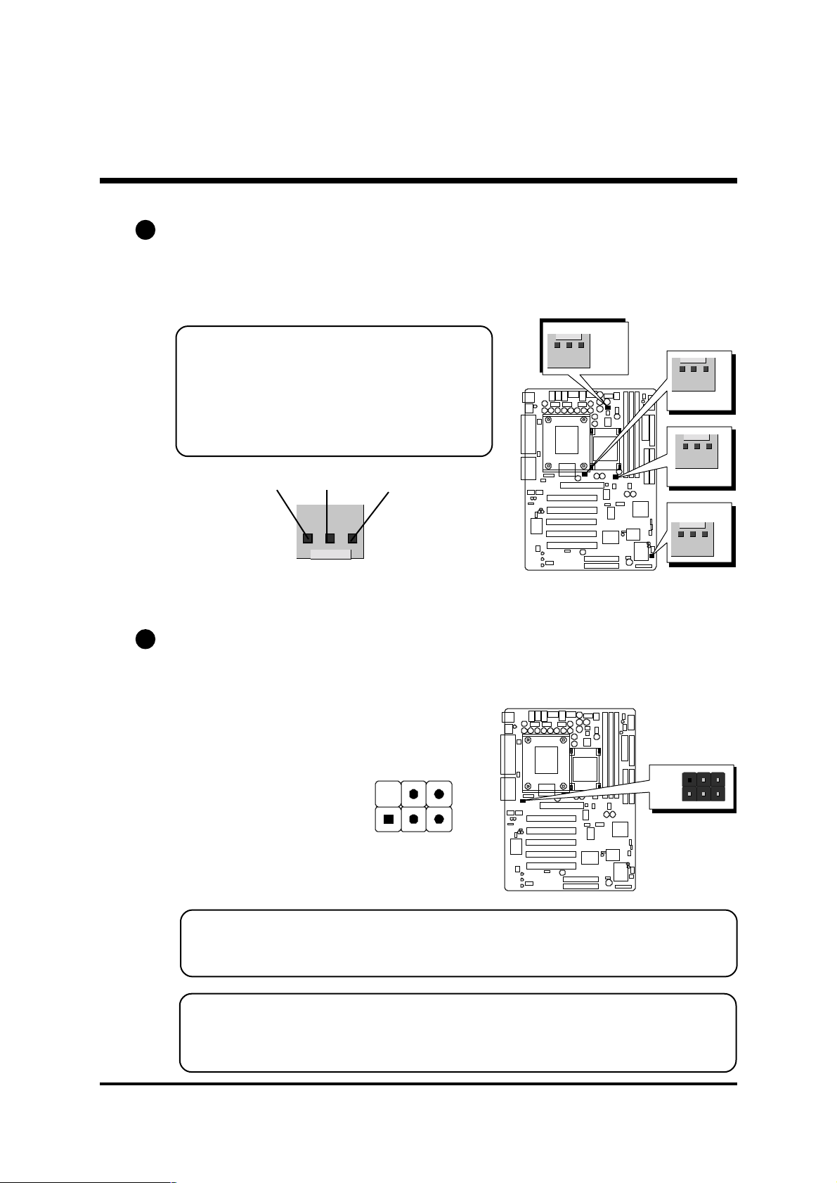
E2
CPU, AGP, Chipset and System Fan connectors - FAN1/2/3/4
The mainboard provides four onboard 12V cooling fan power connectors to
support CPU (FAN1), AGP (FAN2), Chipset (FAN3) or System (FAN4) cooling
fans.
Note:
Both cable wiring and type of plug may vary
, which depends on the fan maker. Keep in
mind that the red wire should always be
connected to the +12V header and the black
wire to the ground (GND) header.
GND +12V
E3
IR Header (JP16)
If you have an Infrared device, this mainboard can implement IR transfer
function. To enable the IR transfer function, follow these steps:
Pins Assignment:
SENSE
1
FAN1/2/3 with rotate sense.
FAN4 without rotate sense.
FAN11
1
FAN2
1
FAN4
1
FAN3
1=NC
2=KEY
2 4 6
JP16
1
3=+5V
4=GND
5=IRTX
1 3 5
6=IRRX
Note: Before connect your IR device, please be sure each IR on board pin
allocation is matchable with the pin of the IR device. Otherwise,
incorrect IR connection may do damage to your IR device.
Step 1. Attach the 6-pin infrared device cable to JP16.
(Refer to the above diagram for IR pin assignment.)
Step 2. This mainboard support Normal transfer modes.
- 41 -
Page 44
E4
Audio CD_IN Connector (CN5) (Black)
Port CN5 is used to attach an audio connector cable from the CD-ROM drive.
4 3 2 1
Pin Assignments:
1=CD-L 2=CD-GND
3=CD-GND 4=CD-R
E5
Audio AUXILIARY_IN Connectorr (CN4) (White)
Port CN4 can be used to connect a stereo audio input from CD-ROM, TV-tuner
or MPEG card.
4 3 2 1
Pin Assignments:
CN4
CN5
1
CD-IN
AU X_IN
1
1=AUXL 2=AGND
3=AGND 4=AUXR
E6
Audio Bass/Center_Out Header (JP18)
JP18 header can be used to connect the cable which attached to bass/center
amplified speakers.
4 3 2 1
Pin Assignments:
1=LENTER 2=CD-GND
3=CD-GND 4=BASS
- 42 -
BASS
1
JP18
Page 45

E7
Wake-On-LAN Connector (JP3)
Attach a 3-pin connector through the LAN card which supports the Wake-OnLAN (JP3) function. This function lets users wake up the connected system
through the LAN card.
3 2 1
Pins Assignment:
1=Power 2=GND
3=RING#
E8
Smart Card header (JP15)
JP15 header can be used to connect the smart card reader device cable which
attached to Smart Card Reader.
JP3
WOL
13 11 9 7 5 3 1
14 12 1 0 8 6 4 2
Pin Assignments:
1=VCC 2=NC
3=NC 4=NC
5=SCRFET# 6=SCRREST
7=SCRCLK 8=RFU
9=NC 10=SCRIO
11=GND 12=SCRPRES#
13=NC 14=NC
- 43 -
JP15
Smart R eader
1
Page 46

3.3 System Memory Configuration
The AB30/AB30R mainboard has three 168-pin DIMM slots that allow you to
install from 16MB up to 3GB of system memory with SDRAM (Synchronous
DRAM). Each DIMM (Dual In-line Memory Module) slot can accommodate
16MB, 32MB, 64MB, 128MB, 256MB and 512MB 3.3V single or double
side SDRAM modules. DIMM slots are arranged in three banks, each
memory bank made of one slot and providing a 64-bit wide data path.
1. Install Memory:
Install memory in any or all of the banks. The combination shown as follows.
DIMM
Slot
DIMM 1
DIMM 2
DIMM 3
Memory Modules
16MB, 32MB, 64MB, 128MB, 256MB, 512M and
1GB 168-pin 3.3V SDRAM DIMM
16MB, 32MB, 64MB, 128MB, 256MB, 512M and
1GB 168-pin 3.3V SDRAM DIMM
16MB, 32MB, 64MB, 128MB, 256MB, 512M and
1GB 168-pin 3.3V SDRAM DIMM
Mod ule
Quantity
x 1
x 1
x 1
Note: You do not need to set any jumper to configure memory since the
BIOS utility can detect the system memory automatically. You can
check the total system memory value in the BIOS Standard CMOS
Setup menu.
2. Upgrade Memory:
You can easily upgrade the system memory by inserting additional SDRAM
modules in available DIMM banks. The total system memory is calculated by
simply adding up the memory in all DIMM banks After upgrade, the new
system memory value will automatically be computed and displayed in the
field "
Standard CMOS Setup" of BIOS setup program.
- 44 -
Page 47

4 SOFTW ARE UTILITY
4.1 Mainboard CD Overview
Note: The CD contents attached in AB30/AB30R mainboard are subject to
change without notice.
To start your mainboard CD disc, just insert it into your CD-ROM drive and
the CD AutoRun screen should appear. If the AutoRun screen does not
appear, double click or run D:\Autorun.exe (assuming that your CD-ROM
drive is drive D:)
Navigation Bar Description:
F Install Mainboard AB30 Software - Installing chipset, Ultral ATA and
Hardware audio drivers.
F Install Mainboard AB30R Software - Installing chipset, Ultral ATA,
Hardware audio , and IDE RAID drivers.
F Manual - AB30/AB30R Series mainboard and IDE RAID (AB30R only)
user's manual in PDF format.
F Link to Shuttle Homepage - Link to shuttle website homepage.
F Browse this CD - Allows you to see contents of this CD.
F Quit - Close this CD.
- 45 -
Page 48

4.2 Install Mainboard Software
Insert the attached CD into your CD-ROM drive and the CD AutoRun screen
should appear. If the AutoRun screen does not appear, double click on
Autorun icon in My Computer to bring up Shuttle Mainboard Software
Setup screen.
Select using your pointing device (e.g. mouse) on the Install Mainboard
AB30 Software" or Install Mainboard AB30R Software" bar to run into
sub-menu.
The Mainboard AB30 Software include:
[4.2.A] Install Chipset System Driver
[4.2.B] Install Intel Ultra ATA Driver
[4.2.C] Install Audio Driver (Hardware Audio Software)
The Mainboard AB30R Software include:
[4.2.A] Install Chipset System Driver
[4.2.B] Install Intel Ultra ATA Driver
[4.2.C] Install Audio Driver (Hardware Audio Software)
[4.2.D] Install promise 20265R RAID Driver
- 46 -
Page 49

4.2.A Install Chipset System Driver
Select using your pointing device (e.g. mouse) on the Install Chipset System
Driver bar to install chipset system driver.
AB30
AB30R
Once you made your selection, a Setup window run the installation
automatically.
When the copying files is done, make sure you reboot the system to take the
installation effect.
P.S.: After the first reboot, the system will continue the setup procedure and
then reboot automatically. Please must be sure the complete installation.
Note: When the Windows 95/98 first reboot after Intel Chipset System
drivers installed, some new hardware devices will be found and added. For
those new hardware devices, related software driver will be searched for
installing. The user may find the software drivers retain on directory
C:\windows\system if some of software drivers could not be found during
searching.
- 47 -
Page 50

4.2.B Install IDE Driver
This driver may do bad effect on some model or brand of IDE HDD devices.
Hereby, we won't suggest users to install it cause it might crash your HDD
data. However, if you are very sure that the driver matches your IDE HDD,
please follow below indication to complete setup.
Select using your pointing device (e.g. mouse) on the Install Intel Ultra ATA
Driver bar to install Ultra ATA IDE driver.
P.S.: Before doing this IDE Driver installation, setup Chipset System Driver is
necessary.
AB30
AB30R
Once you made your selection, a Setup window run the installation
automatically.
When the copying files is done, make sure you reboot the system to take the
installation effect.
- 48 -
Page 51

4.2.C Install Audio Driver
Select using your pointing device (e.g. mouse) on the Install Audio Driver
bar to install audio driver.
AB30
AB30R
Once you made your selection, a Setup window run the installation
automatically.
When the copying files is done, make sure you reboot the system to take the
installation effect.
- 49 -
Page 52

4.2.D Install IDE RAID Driver (AB30R only)
Select using your pointing device (e.g. mouse) on the Install promise
20265R RAID Driver bar.
AB30R
Cause the IDE RAID driver can't be setup automatically, please follow below
instructions to complete the installation. As you install the IDE RAID driver, a
readme windows runs out as below.
Once you made your selection, a Setup window run the installation
automatically.
When the copying files is done, make sure you reboot the system to take the
installation effect.
- 50 -
Page 53

4.3 View the User's Manual
Insert the attached CD into your CD-ROM drive and the CD AutoRun screen
should appear. If the AutoRun screen does not appear, double click on
AutoRun icon in My Computer to bring up Shuttle Mainboard Software
Setup screen.
Select using your pointing device (e.g. mouse) on the Manual bar.
Then Online Information windows will appear on your screen. Click on the
Install Acrobe Reader bar if you need to install acrobe reader.
Then click on "AB30/AB30R Manual" bar to view user's manual, and click
on "IDE Raid Manual" bar to view IDE RAID user's manual. (AB30R only)
- 51 -
Page 54

5 BIOS SETUP
AB30/AB30R BIOS ROM has a built-in Setup program that allows users to
modify the basic system configuration. This information is stored
in battery-backed RAM so that it retains the Setup information even if the
system power is turned off.
The system BIOS is managing and executing a variety of hardware related
functions in the system, including:
System date and time
Hardware execution sequence
Power management functions
Allocation of system resources
5.1 Enter the BIOS
To enter the BIOS (Basic Input / Output System) utility, follow these steps:
Step 1. Power on the computer, and the system will perform its
POST (Power-On Self Test) routine checks.
Step 2. Press <Del> key immediately, or at the following message:
Press DEL to enter SETUP
,or simultaneously press <Ctrl>, <Alt>, <Esc> keys
Note 1. If you miss trains of words meationed in step2 (the message
disappears before you can respond) and you still wish to enter BIOS
Setup, restart the system and try again by turning the computer OFF
and ON again or by pressing the <RESET> switch located at the
computers front-panel. You may also reboot by simultaneously
pressing the <Ctrl>, <Alt>, <Del> keys.
Note 2. If you do not press the keys in time and system does not boot, the
screen will prompt an error message, and you will be given the
following options:
Press F1 to Continue, DEL to Enter Setup
Step 3. As you enter the BIOS program, the CMOS Setup Utility will
prompt you the Main Menu, as shown in the next section.
- 52 -
Page 55

5.2 The Main Menu
Once you enter the AwardBIOS(tm) CMOS Setup Utility, the Main
Menu will appear on the screen. The Main Menu allows you to select
from several setup functions and two exit choices. Use the arrow keys
to select among the items and press <Enter> to accept and enter the
sub-menu.
Note that a brief description of each highlighted selection appears at the
bottom of the screen.
Setup Items
The main menu includes the following main setup categories. Recall
that some systems may not include all entries.
Standard CMOS Features
Use this menu for basic system configuration.
Advanced BIOS Features
Use this menu to set the Advanced Features available on your system.
Advanced Chipset Features
Use this menu to change the values in the chipset registers and optimize your system's performance.
Integrated Peripherals
Use this menu to specify your settings for integrated peripherals.
Power Management Setup
Use this menu to specify your settings for power management.
- 53 -
Page 56

PnP / PCI Configurations
This entry appears if your system supports PnP / PCI.
PC Health Status
This entry shows the current system temperature, Voltage, and FAN
speed.
Frequency/Voltage Control
Use this menu to specify your settings for frequency/voltage control.
Load Fail-Safe Defaults
Use this menu to load the BIOS default values for the minimal/stable
performance of your system to operate.
Load Optimized Defaults
Use this menu to load the BIOS default values that are factory-set for
optimal performance system operation. While Award has designed the
custom BIOS to maximize performance, the factory has the right to
change these defaults to meet users' needs.
Supervisor / User Password
Use this menu to change, set, or disable supervisor/user password. It
allows you to limit access to the system and Setup, or only to Setup.
Save & Exit Setup
Save CMOS value changes in CMOS and exit from setup.
Exit Without Saving
Abandon all CMOS value changes and exit from setup.
- 54 -
Page 57

( Standard CMOS Features
The items in Standard CMOS Setup Menu are divided into 10 categories. Each category includes no, one or more than one setup items.
Use the arrow keys to highlight the item and then use the <PgUp> or
<PgDn> keys to select the value you want in each item.
Date
<Month> <DD> <YYYY>
Set the system date. Note that the 'Day' automatically changes when
you set the date.
Time
<HH : MM : SS>
The time is converted based on the 24-hour military-time clock. For
example, 5 p.m. is 17:00:00.
IDE Primary Master
Options are in its sub-menu.
Press <Enter> to enter the sub-menu of detailed options.
IDE Primary Slave
Options are in its sub-menu.
Press <Enter> to enter the sub-menu of detailed options.
- 55 -
Page 58

IDE Secondary Master
Options are in its sub-menu.
Press <Enter> to enter the sub-menu of detailed options.
IDE Secondary Slave
Options are in its sub menu.
Press <Enter> to enter the sub-menu of detailed options.
Drive A/Drive B
Select the type of floppy disk drive installed in your system.
Ø The choice: None, 360K, 5.25 in, 1.2M, 5.25 in, 720K, 3.5 in,
1.44M, 3.5 in, or 2.88M, 3.5 in.
Video
Select the default video device.
Ø The choice: EGA/VGA, CGA 40, CGA 80, or MONO.
Halt On
Select the situation in which you want the BIOS to stop the POST
process and notify you.
Ø The choice: All Errors, No Errors, All, But Keyboard, All, But
Diskette, or All, But Disk/Key.
Base Memory
Displays the amount of conventional memory detected during boot up.
Ø The choice: N/A.
Extended Memory
Displays the amount of extended memory detected during boot up.
Ø The choice: N/A.
Total Memory
Displays the total memory available in the system.
Ø The choice: N/A.
- 56 -
Page 59

******************************************************
IDE Adapters
The IDE adapters control the hard disk drive. Use a separate sub-menu
to configure each hard disk drive.
IDE HDD Auto-Detection
Press <Enter> to auto-detect HDD on this channel. If detection is
successful, it fills the remaining fields on this menu.
Ø Press Enter
IDE Primary Master
Selecting 'manual' lets you set the remaining fields on this screen and
select the type of fixed disk. "User Type" will let you select the number
of cylinders, heads, etc., Note: PRECOMP=65535 means
NONE !
Ø The choice: None, Auto, or Manual.
Access Mode
Choose the access mode for this hard disk.
Ø The choice: CHS, LBA, Large, or Auto.
Capacity
Disk drive capacity (Approximated). Note that this size is usually
slightly greater than the size of a formatted disk given by a disk checking program.
Ø Auto-Display your disk drive size.
The following options are selectable only if the 'IDE Primary Master'
item is set to 'Manual'
Cylinder
Set the number of cylinders for this hard disk.
Ø Min = 0, Max = 65535
Head
Set the number of read/write heads.
Ø Min = 0, Max = 255
- 57 -
Page 60

Precomp
Warning: Setting a value of 65535 means no hard disk.
Ø Min = 0, Max = 65535
Landing zone
Set the Landing zone size.
Ø Min = 0, Max = 65535
Sector
Number of sector per track.
Ø Min = 0, Max = 255
******************************************************
- 58 -
Page 61

( Advanced BIOS Features
This section allows you to configure your system for basic operation.
You have the opportunity to select the system's default speed, boot-up
sequence, keyboard operation, shadowing, and security.
Virus Warning
Allows you to choose the VIRUS Warning feature for IDE Hard Disk boot
sector protection. If this function is enables and someone attempts to
write data into this area, BIOS will show a warning message on screen,
and an alarm beep.
Enabled Activates automatically when the system boots up,
causing a warning message to appear when anything
attempts to access the boot sector or hard disk partition table.
Disabled No warning message will appear when anything
attempts to access the boot sector or hard disk partition table.
Ø The choice: Enabled or Disabled.
Quick Power On Self Test
This item speeds up Power-On Self Test (POST) after you power on the
computer. If it is set to enabled, BIOS will shorten or skip some check
items during POST.
Ø The choice: Enabled, or Disabled.
- 59 -
Page 62

Hard Disk Boot Priority
The item select Hard Disk Boot device priority.
Ø The Choice: HDD-0, HDD-1, HDD-2, HDD-3, HDD-4, or HDD-5.
First/Second/Third Boot Device
The BIOS attempts to load the operating system from the devices in the
sequence selected in these items.
Ø The Choice: Floppy, LS120, Hard Disk, CDROM, ZIP100, LAN, or
Disabled.
Boot Other Device
Select Your Boot Device Priority.
Ø The choice: Enabled or Disabled.
Swap Floppy Drive
If the system has two floppy drives, you can swap the logical drive
name assignment.
Ø The choice: Enabled or Disabled.
Boot Up Floppy Seek
Seeks disk drives during boot-Up. Disabling speed boots up.
Ø The choice: Enabled or Disabled.
Boot Up NumLock Status
Selects power-on state for NumLock.
Ø The choice: Off or On.
Gate A20 Option
This entry allows you to select how the gate A20 is handled. The gate
A20 is a device used for above 1MByte of address memory. Initially,
the gate A20 was handled via a pin on the keyboard. Today, while a
keyboard still provides this support, it is more common and much faster
in setting to Fast for the system chipset to provide support for gate A20.
Ø The choice: Normal, or Fast.
Typematic Rate Setting
Keystrokes repeat at a rate determined by the keyboard controller.
When this controller enabled, the typematic rate and typematic delay
can be selected.
Ø The choice: Enabled or Disabled.
- 60 -
Page 63

Typematic Rate (Chars/Sec)
This item sets how many times the keystroke will be repented in a
second when you hold the key down.
Ø The choice: 6, 8, 10, 12, 15, 20, 24, or 30.
Typematic Delay (Msec)
Sets the delay time after the key is held down before it begins to repeat
the keystroke.
Ø The choice: 250, 500, 750, or 1000.
Security Option
Select whether the password is required every time the system boots or
only when you enter setup.
System The system will not boot and access to Setup will be
denied if the correct password is not entered promptly.
Setup The system will boot, but access to Setup will be
denied if the correct password is not entered promptly.
Ø The choice: System or Setup.
Note: To disabled security, select PASSWORD SETTING at Main
Menu, and then you will be asked to enter password. Do not
type anything and just press <Enter>; it will disable security.
Once the security is disabled, the system will boot, and you
can enter Setup freely.
APIC Mode
Selects enable/disable IO APIC function
Ø The choice: Enabled or Disabled.
MPS Version Control For OS
Selects the operating system multiprocessor support version.
Ø The choice: 1.1 or 1.4
OS Select For DRAM > 64MB
Selects the operating system that is running with greater than 64MB of
RAM in the system.
Ø The choice: Non-OS2 or OS2.
- 61 -
Page 64

Report No FDD For Win 95
Whether report no FDD runs for Win 95 or not.
Ø The choice: Yes or No.
Small Logo(EPA) Show
This item allows you to enable/disable the EPA Logo.
Ø The choice: Enabled or Disabled.
- 62 -
Page 65

( Advanced Chipset Features
This section allows you to configure the system based on the specific features
of the installed chipset. This chipset manages bus speeds and access to system memory resources, such as DRAM and the external cache. It also coordinates communications between the conventional ISA bus and the PCI bus.
It states that these items should never need to be altered.
The default settings have been chosen because they provide the best operating conditions for your system. If you discovered that data was being lost
while using your system, you might consider making any changes.
DRAM Timing Selectable
This item select the DRAM Timing by SPD (Serial Presence Data) or by
manual selection.
Ø The Choice: Manual or By SPD.
In some SDRAM module , there is no SPD on it, select by SPD will
cause system can not boot.
CAS Latency Time
This item select SDRAM CAS latency. (1.5T, 2T, 2.5T, or 3T)
Ø The Choice: 1.5, 2, 2.5, or 3.
Active to Precharge Delay
This item select the SDRAM Active to Precharge Delay. (7T, 6T, or 3T)
Ø The Choice: 7, 6, or 5.
- 63 -
Page 66

DRAM RAS# to CAS# Delay
This field lets you insert a timing delay between the CAS and RAS
strobe signals, and you can use it when DRAM is written to, read from,
or refreshed. Faster performance is gained in high speed, more stable
performance, in low speed. This field is applied only when synchronous DRAM is installed in the system.
Ø The Choice: 3 or 2.
DRAM RAS# Precharge
If an insufficient number of cycles is allowed for the RAS to accumulate
its charge before DRAM refresh, the refresh may be-incompleted, and
the DRAM may fail to retain data. Fast gives faster performance; and
Slow gives more stable performance. This field is applied only
when synchronous DRAM is installed in the system.
Ø The Choice: 3 or 2.
DRAM Data Integrity Mode
This item enable/disable SDRAM ECC support.
Ø The Choice: Non-ECC or ECC.
Memory Frequency For
This item select SDRAM Frequency.
Ø The Choice: PC100 or PC133.
Dram Read Thermal Mgmt
This item Enable/Disable DRAM read thermal management function.
Ø The choice: Enabled or Disabled.
System BIOS Cacheable
Selecting Enabled allows caching of the system BIOS ROM at F0000hFFFFFh, resulting in better system performance. However, if any program is written to this memory area, a system error may result.
Ø The choice: Enabled or Disabled.
Video BIOS Cacheable
Selecting Enabled allows caching of the video BIOS , resulting in better
system performance. However, if any program is written to this memory
area, a system error may result.
Ø The Choice: Enabled or Disabled.
- 64 -
Page 67

Video RAM Cacheable
Selecting Enabled allows caching of the video RAM , resulting in better
system performance. However, if any program is written to this memory
area, a system error may result.
Ø The Choice: Enabled or Disabled.
Memory Hole At 15M-16M
You can reserve this area of system memory for ISA adapter ROM.
When this area is reserved, it cannot be cached. The user information
of peripherals that need to use this area of system memory usually
discusses their memory requirements.
Ø The Choice: Enabled or Disabled.
Delayed Transaction
The chipset has an embedded 32-bit posted write buffer to support
delayed transactions cycles. Select Enabled to support compliance with
PCI specification version 2.1.
Ø The Choice: Enabled or Disabled.
AGP Aperture Size (MB)
Select the size of Accelerated Graphics Port (AGP) aperture. The aperture is a portion of the PCI memory address range dedicated to graphics
memory address space. Host cycles that hit the aperture range are
forwarded to the AGP without any translation.
Ø The Choice: 4, 8, 16, 32, 64, 128, or 256.
Delay Prior to Thermal
This item select the Delay time before thermal controller activate from
temperature too high.
Ø The Choice: 4 Min, 8 Min, 16 Min, or 32 Min.
- 65 -
Page 68

( Integrated Peripherals
On-Chip Primary PCI IDE
The integrated peripherals controller contains an IDE interface with
support to two IDE channels. Select Enabled to activate each channel
separately.
Ø The choice: Enabled or Disabled.
IDE Primary Master/Slave PIO
The two IDE PIO (Programmed Input/Output) fields let you set a PIO
mode (0-4) for each of the two IDE devices that the onboard IDE interface supports. Modes 0 through 4 provide successively increased
performance. In Auto mode, the system automatically determines the
best mode for each device.
Ø The choice: Auto, Mode 0, Mode 1, Mode 2, Mode 3, or Mode 4.
IDE Primary Master/Slave UDMA
Ultra DMA33/66/100 implementation is possible only if your IDE hard
drive supports it and the operating environment includes a DMA driver
(Windows 95 OSR2 or a third-party IDE bus master driver). If both of
- 66 -
Page 69

your hard drive and your system software support Ultra DMA33/66/
100, select Auto to enable BIOS support.
Ø The Choice: Auto or Disabled.
On-Chip Secondary PCI IDE
The integrated peripherals controller contains an IDE interface with
support to two IDE channels. Select Enabled to activate each channel
separately.
Ø The choice: Enabled or Disabled.
IDE Secondary Master/Slave PIO
The two IDE PIO (Programmed Input/Output) fields let you set a PIO
mode (0-4) for each of the two IDE devices that the onboard IDE interface supports. Modes 0 through 4 provide successively increased
performance. In Auto mode, the system automatically determines the
best mode for each device.
Ø The choice: Auto, Mode 0, Mode 1, Mode 2, Mode 3, or Mode 4.
IDE Secondary Master/Slave UDMA
Ultra DMA33/66/100 implementation is possible only if your IDE hard
drive supports it and the operating environment includes a DMA driver
(Windows 95 OSR2 or a third-party IDE bus master driver). If both of
your hard drive and your system software support Ultra DMA33/66/
100, select Auto to enable BIOS support.
Ø The Choice: Auto or Disabled.
USB Controller
Select Enabled if your system contains a Universal Serial Bus (USB)
controller and you have USB peripherals.
Ø The choice: Enabled or Disabled.
USB Keyboard Support
Select Enabled if your system contains a Universal Serial Bus (USB)
controller and you have a USB keyboard.
Ø The choice: Enabled or Disabled.
AC97 Audio
This item allows you to select AC97 CODEC audio chip to support
Audio.
Ø The choice: Audio or Disabled.
- 67 -
Page 70

Init Display First
This item allows you to decide to activate whether PCI Slot or AGP Slot
first.
Ø The choice: PCI Slot or AGP .
CMedia CMI8738 Audio
This item allows you to select CMI8738 Audio chip to support Audio.
Ø The choice: Enabled, or Disabled
IDE HDD Block Mode
Block mode is also called block transfer, multiple commands, or multiple sector read/write. If your IDE hard drive supports block mode
(most new drives do), select Enabled for automatic detection of the
optimal number of block read/writes per sector the drive can support.
Ø The choice: Enabled, or Disabled
POWER ON Function
This item is used to defined Keyboard & PS/2 mouse power-on function
enabled or disabled.
Ø The choice:Hot-KEY, Mouse Click, Any KEY, Button Only, Keyboard
98.
Note USB Keyboard, USB Mouse and Serial Mouse are not
supported to this function.
Hot Key Power ON
Power-on by soft-on/off button and keyboard are available.
Ø The choice: <Ctrl><F1> to <Ctrl><F12>.
Onboard FDC Controller
This item specifices onboard floppy disk drive controller. This setting
allows you to connect your floppy disk drives to the onboard floppy
connector. Choose the "Disabled" settings if you have a separate
control card.
Ø The choice: Enabled Disabled.
Onboard Serial Port1/Port2
Select an address and corresponding interrupt for the first and second
serial ports.
Ø The choice: 3E8/IRQ4, 2E8/IRQ3, 3F8/IRQ4, 2F8/IRQ3,Auto, or
Disabled.
- 68 -
Page 71

Onboard Parallel Port
This item allows you to determine onboard parallel port controller I/O
address setting.
Ø The choice:: 378/IRQ7, 278/IRQ5, 3BC/IRQ7, or Disabled.
Parallel Port Mode
Select an operating mode for the onboard parallel (printer) port. Select
Normal, Compatible, or SPP unless you are certain your hardware and
software both support one of the other available modes.
Ø The choice: SPP, EPP, ECP, or ECP+EPP.
ECP Mode Use DMA
Select a DMA channel for the parallel port for use during ECP mode.
Ø The choice: 1 or 3.
PWRON After PWR-Fai
This item select power on function when power fail.
Ø The choice: Off, On, or Former-Sts..
Game Port Address
This item selects Game Port Address.
Ø The choice: Disabled, 201, or 209.
Midi Port Address
This item selects Midi Port Address.
Ø The choice: Disabled, 330, or 300.
Midi Port IRQ
This item selects Midi Port IRQ.
Ø The choice: 5 or 10.
CIR Port Address
This item selects CIR Port Address.
Ø The choice: Disabled, 310, or 320.
CIR Port IRQ
This item selects CIR Port IRQ
Ø The choice: 11 or 5.
- 69 -
Page 72
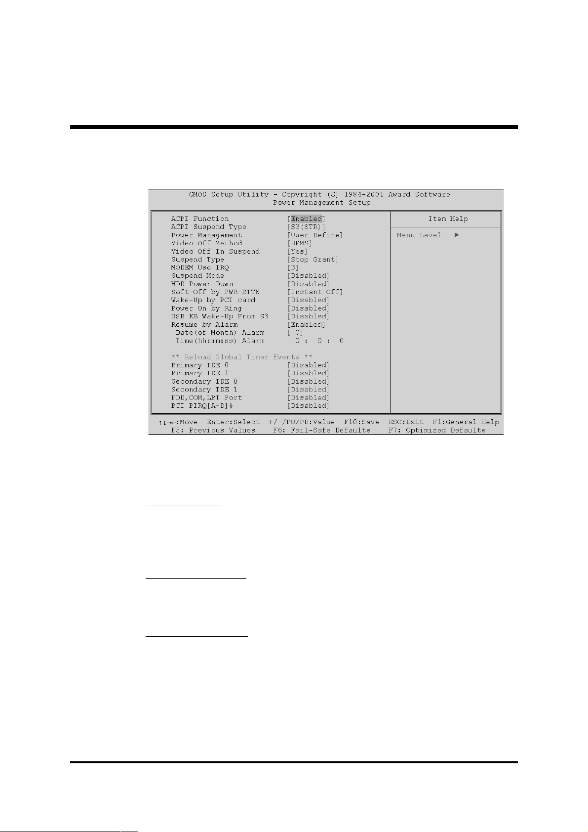
( Power Management Setup
The Power Management Setup allows you to configure your system to
most effectively saving energy while operating in a manner consistent
with your own style of computer use.
ACPI Function
This item allows you to enable/disable the Advanced Configuration and
Power Management (ACPI)
Ø The choice: Enabled or Disabled.
ACPI Suspend Type
This item allows you to select sleep state when suspend.
Ø The choice: S1(POS) or S3(STR).
Power Management
This category allows you to select the type (or degree) of power saving
and is directly related to the following modes:
1. Suspend Mode
2. HDD Power Down
Min Saving Minimum power management.
Suspend Mode=
HDD Power Down=15min.
1 hr.
- 70 -
Page 73

Max Saving Maximum power management.
Suspend Mode=1min.
HDD Power Down=1min.
User Define Allows you to set each mode individually.
When this item not disabled, each of the
ranges are from 1 min. to 1 hr. except for HDD
Power Down which ranges from 1 min. to 15
min. and disable.
Ø The choice: User Define, Min Saving, or Max Saving.
Video Off Method
This determines the manner in which the monitor is blanked.
V/H SYNC+Blank This selection will cause the system to turn off
the vertical and horizontal synchronization
ports and write blanks to the video buffer.
Blank Screen This option only writes blanks to the video
buffer.
DPMS Initial display power management signaling.
Ø The choice: V/H SYNC+Blank, Blank Screen, or DPMS.
Video Off In Suspend
This item determines the manner in which the monitor is blanked.
Ø The choice: Yes or No.
Suspend Type
This item allows you to select the Suspend Type.
Ø The choice: PwrOn Suspend, Stop Grant.
MODEM Use IRQ
This item determines the IRQ in which the MODEM can use.
Ø The choice: 3, 4, 5, 7, 9, 10, 11, or NA.
Suspend Mode
When this item enabled and after the set up time of system inactivity, all
devices except the CPU will be shut off.
Ø The choice: Disabled, 1 Min, 2 Min, 4 Min, 8 Min, 12 Min,
20 Min, 30 Min, 40 Min, or 1 Hour.
- 71 -
Page 74

HDD Power Down
When this item enabled and after the set up time of system inactivity,
the hard disk drive will be powered down while all other devices
remain active.
Ø The choice: Disabled or 1 Min~15 Min.
Soft-Off by PWR-BTTN
Pressing the power button for more than 4 seconds forces the system to
enter the Soft-Off state when the system has "hung.".
Ø The choice: Instant-Off or Delay 4 Sec.
Wake-Up by PCI card
This item Enabled/Disabled PCI card wakeup for PCI Spec 2.2.
Ø The choice: Enabled or Disabled.
Power On by Ring
This item determine the system will resume by activating of modem
ring.
Ø The choice: Enabled or Disabled.
USB KB Wake-Up Fram S3
Set the item Enabled, users can awaken the system by USB keyboard.
Ø The choice: Disabled or Enabled.
Resume by Alarm
When this item enabled, your can set the date and time at which the
RTC (real-time clock) alarm awakens the system from Suspend mode.
Ø The choice: Disabled or Enabled.
Data (of Month) Alarm
This item selects the alarm date.
Ø Key in a DEC number:Min=0, Max=31.
Time (hh:mm:ss) Alarm
This item selects the alarm Time.
[hh]
Ø Key in a DEC number:Min=0, Max=23.
[mm/ss]
Ø Key in a DEC number:Min=0, Max=59.
- 72 -
Page 75

*** Reload Global Timer Events ***
If any of these items is set to Disabled, system will not monitor the
activity event and reload global timer.
If these items is set to Enabled, system will monitor the system activity
event; if any of the events it monitored, it will cause system to reload
global timer.
These items include Primary IDE0/1, Secondary IDE 0/1, Floppy Disk,
Serial Port, Parallel Port, and PCI PIRQ[A-D]#.
Ø The choice: Disabled or Enabled.
- 73 -
Page 76
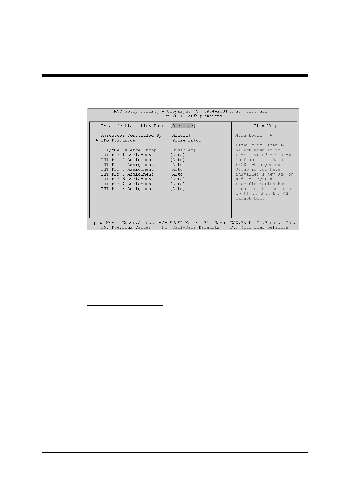
( PnP/PCI Configurations
This section describes the configuration of PCI bus system. PCI or
Personal Computer Interconnection is a system which allows I/O
devices to operate at the speed CPU itself keeps when CPU
communicating with its own special components.
This section covers some very technical items, and it is strongly
recommended that only experienced users should make any
changes to the default settings.
Reset Configuration Data
Normally, you leave this field Disabled. Select Enabled to reset
Extended System Configuration Data (ESCD) when you exit from Setup
if you have installed a new device or software and the system
reconfiguration has caused such a serious conflict that the operating
system can not boot.
Ø The choice: Enabled or Disabled .
Resource controlled By
The Award Plug-and-Play BIOS has the capacity to automatically
configure all of the boot and Plug-and-Play compatible devices.
However, this capability means absolutely nothing unless you are using
a Plug-and-Play operating system such as Windows 95.
If you set this field to "manual" , choose specific resources by going into
each of the sub-menu that follows this field (a sub-menu is proceeded
by a ">").
Ø The choice: Auto(ESCD) or Manual.
- 74 -
Page 77

IRQ Resources
When resources are controlled manually, assign each system interrupt a
type, depending on the type of device using the interrupt.
IRQ3/4/5/7/9/10/11/12/14/15 assigned
This item allows you to determine the IRQ assigned to the ISA bus and
is not available to any PCI slot. Legacy ISA for devices is compliant with
the original PC AT bus specification; PCI/ISA PnP for devices is compliant with the Plug-and-Play standard whether designed for PCI or ISA
bus architecture.
Ø The choice: PCI Device or Reserved.
PCI/VGA Palette Snoop
Leave this field Disabled.
Ø The choice: Enabled or Disabled.
INT Pin 1/2/3/4/5/6/7/8 Assignment
Names the interrupt request (IRQ) line assigned to PCI 1 throught PCI 8
on system. Activity of selected PCI slot awakens system.
Ø The choice: Auto, 3, 4, 5, 7, 9, 10, 11, 12, 14, or 15.
- 75 -
Page 78

( PC Health Status
Shutdown Temperature
Enables you to set the maximum temperature the system can reach
before powering down.
Ø The choice: Disabled, 60°C/140°F, 65°C/149°F, 70°C/158°F.
System Component Characteristics
These fields provide you with information about the systems current
operating status. You cannot make changes to these fields.
The fields include
Voltage 0
Voltage 1
Voltage 2
Voltage 3
Voltage 4
Voltage 5
Voltage 6
Voltage 7
Voltage Battery
Temperature 1
Temperature 2
- 76 -
Page 79

Temperature 3
Fan 1 Speed
Fan 2 Speed
Fan 3 Speed
- 77 -
Page 80

( Frequency/Voltage Control
CPU Vcore Select
This item allows you to select the CPU Vcore.
Ø The choice: Default, 1.100V ~ 1.850V.
CPU Clock Ratio
This item allows you to adjust CPU Ratio.
Ø The choice: x8 ~ x23.
Auto Detect DIMM/PCI Clk
This item allows you to enable/disable auto detection DIMM/PCI Clock.
Ø The choice: Enabled, or Disabled.
Spread Spectrum
This item allows you to enable/disable the spread spectrum modulation.
Ø The choice: Enabled, or Disabled.
CPU Clock
This item allows the user to adjust CPU Host Clock from 100 MHz to
166 MHz by 1 MHz step.
Before you over CPU Host Clock from BIOS setup program, inserting
jumpers properly on JP2 is necessary.
Min: 100 MHz
Man: 166 MHz
Ø Key in a DEC number: (Between Min and Max.)
- 78 -
Page 81

( Load Fail-Safe Defaults
When you press <Enter> on this item, you will get a confirmation
dialog box with a message similar to:
Load Fail-Safe Defaults (Y/N) ? N
Pressing 'Y' loads the BIOS default values for the most stable,
minimal performance system operations.
( Load Fail-Safe Defaults
When you press <Enter> on this item, you will get a confirmation
dialog box with a message similar to:
Load Optimized Defaults (Y/N) ? N
Pressing 'Y' loads the default values that are factory-set for
optimal performance system operation.
- 79 -
Page 82

@ Supervisor/User Password Setting
You can set either supervisor or user password, or both of them. The
differences between them are:
Supervisor Password and User Password
The options on the Password screen menu make it possible to restrict
access to the Setup program by enabling you to set passwords for two
different access modes: Supervisor mode and User mode.
In general, Supervisor mode has full access to the Setup options,
whereas User mode has restricted access to the options. By setting
separate Supervisor and User password, a system supervisor can limit
who can change critical Setup values.
Enter Password
Type the password up to eight characters, and press <Enter>. The
password typed now will clear any previously entered password from
CMOS memory. You will be asked to confirm the password. Type the
password again and press <Enter>. You may also press <Esc> to
abort the selection and not enter a password.
To disable password, just press <Enter> when you are prompted to
enter password. A message will confirm the password being disabled.
Once the password is disabled, the system will boot and you can enter
Setup freely.
- 80 -
Page 83

Password Disable
If you select System at Security Option of BIOS Features Setup Menu,
you will be prompted in entering the password whenever the system is
rebooted or you try to enter Setup. If you select Setup at Security Option of BIOS Features Setup Menu, you will be prompted only when
you try to enter Setup.
Warning : Retain a record of your password in a safe place. If you
forget the password, the only way to access the system is
to clear CMOS, please refer to "Clear CMOS" on page 30.
- 81 -
Page 84

@ Save & Exit Setup
Pressing <Enter> on this item asks for confirmation:
Save to CMOS and EXIT (Y/N)? Y
Pressing "Y" stores the selections made in the menus of CMOS - a
special section of memory that stays on after you turn your system off.
The next time you boot your computer, the BIOS configures your
system according to the Setup selections stored in CMOS. After saving
the values the system is restarted again.
@ Exit Without Saving
Pressing <Enter> on this item asks for confirmation:
Quit without saving (Y/N)? Y
This allows you to exit from Setup without storing in CMOS any
change. The previous selections remain in effect. This exits from the
Setup utility and restarts your computer.
- 82 -
 Loading...