

Page 1

Please short pins 2-3 on jumper
system mainboard.
JPl
before using this
2.
3.
In GREEN CPU inactive mode, the system will stop the
DOS timer. To update the DOS timer, please use
Microsoft POWER.EXE to put the following line in your
config.sys
DEVICE=POWER.EXE STD
file:
Please check the Intel CPU type detected by the BIOS in
the start-up screen:
If the detected Intel CPU is a
80486DX-S
a DX-SL CPU.
or
80486SX-S,
the CPU jumpers must be set for
If the detected Intel CPU is a
80486SX,
the CPU jumpers must be set for a
DX4-S, 80486DX2-S,
80486DX, 80486DX2,
DX/DX2
or
CPU.
The information presented in this publication has been
carefully checked for reliability; however, no responsibility
is assumed for inaccuracies. Specifications are subject to change
without notice.
Trademarks
IBM, PC/AT, and OS/2 are trademarks of International
Business Machines Corporation.
AMD is a trademark of Advanced Micro Devices Inc.
AWARD is a registered trademark of Award Software Inc.
Microsoft is a registered trademark of
Microsoft
Corporation.
Page 2

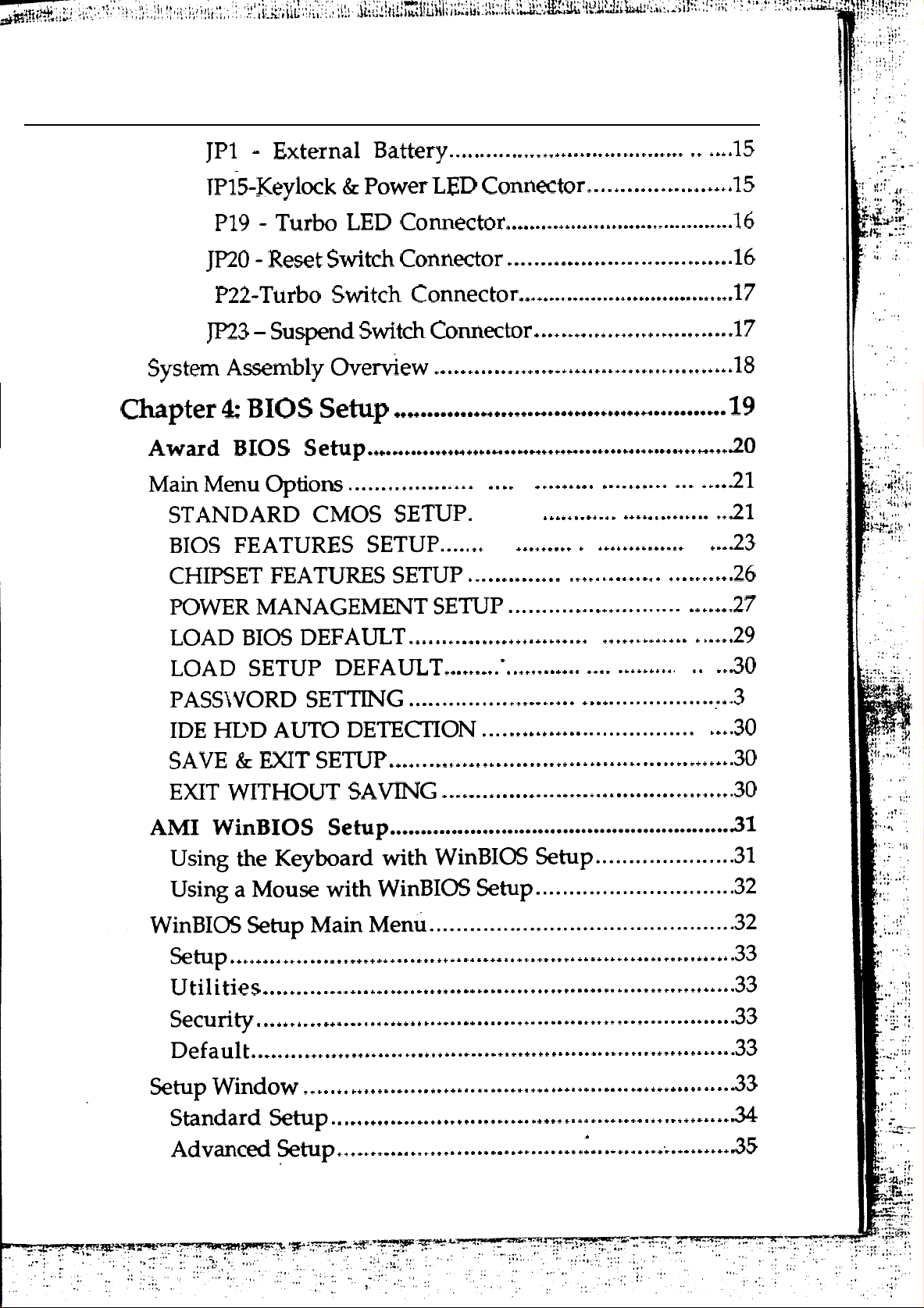
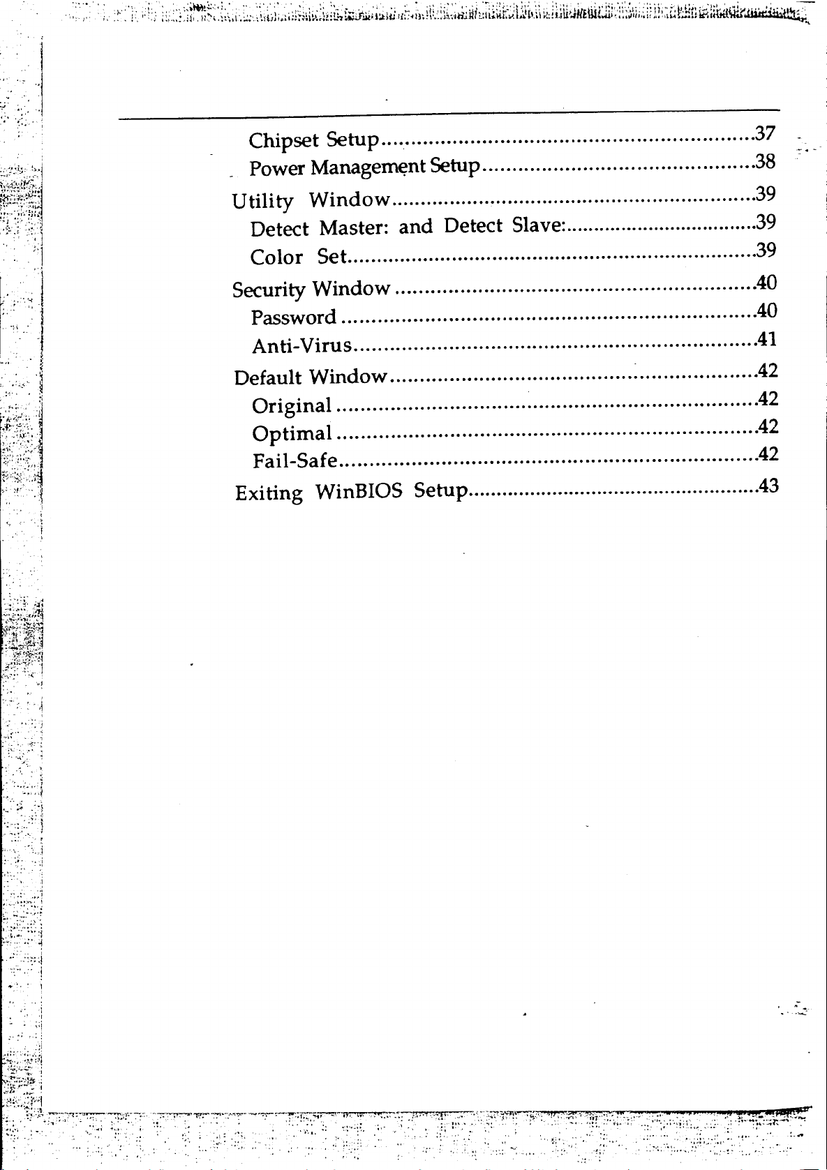
Contents
Chapter 1:
Key Features
Introduction
.....................................................................
Unpacking the Mainboard
Mainboard Layout
.............................................................
..................................................
.................................................
Chapter 2: Hardware Configuration.
Power Precautions
Jumper Switch Settings
JP3
FlashROMVPP
JP27-JP30,
JP6-JP8 -
JP31-
JP34-
Intel
AMD
JP21-JP24,
.............................................................
......................................................
Supply
JP32,
JP33-
CPU Type Jumpers
CPU Clock Setting
80486DX4
80486DX4
JP35-CPU
CPU Clock Multiplier Jumper
CPU Clock Multiplier Jumper . .
Power
Selector..
.....................................
Selectors..
...........................
..
6
.7
.8
.8
....................
..................
....................
1
2
3
4
5
5
5
7
8
JP16 -
VESA Clock
JP17 - VESA Wait State
Memory Configuration
Selector
.......................................................
.......................................
...........................................
Chapter 3: Mainboard Installation
What You Need
Power Supply Requirements
Installing the Mainboard
Connecting
the Mainboard
Connectors
Jl -
Keyboard Connector
J9
- Power Supply Connectors
J18 -
Speaker Connector
...............................................................
..............................................
.................................................
................................................
........................................................................
...........................................
............................................
.................
.....
...
10
10
11
12
13
13
13
....................................
14
14
8
9
9
Page 3
. .
. .
.
.
l
l
:
.
l
l
l
. l
l :
.
l
l
l
*
l
l
l
l
l
l
l
l
l
l
l
l
l
l
l
l
l
l
l .
.
.
.
l
0
Page 4
Page 5

_ Chapter
.
1
Introduction
The 80486 Deep Green mainboard is a 32-bit high-performance
system board. This mainboard is not only compatible with
IBM AT systems, but it also provides power-saving features
that allow the user to program the timer.
You can configure the 80486 Deep Green mainboard for use with
many
Intel
Intel
Intel 80486DX2/DX/SX-SL
Intel
CyrixCX486DX2/DX/S
AMD
UMC U5
486based
P24T
P24D
80486DX4 (P24C)
80486DX2 /
AM486DX4/DX2/DX
microprocessors, such as the following:
DX
/SX
The 80486 Deep Green mainboard features on-board power
management that allows the user to assign system clock rates,
hard disk power saving and display power saving when
entering doze mode, suspend mode or inactive mode.
Page 6

2
Key Features
Advanced features of the 80486 Deep Green mainboard include:
Chapter
Supports
-
Intel
-
Intel
-
Intel
-
Intel
-
Intel
-
-
Ll
Cyrix
AMD AM486DX4 /
uMcu5
write back or write through cache
L2 write back policy for high performance
Flexible cache RAM size
banks or one bank with 16 bytes line size
DRAM auto-detection
CPUs
P24T
80486DX2 /
running at
P24D
80486DX4 (P24C)
DX / SX - SL
80486DX2 /
CX486DX2 /
DX
DX / S
DX2 / DX
/
banking
25/33/40/50/66/75/80/100 MHz:
/SX
64/128/256/512/1024
KB in two
Four banks of DRAM with memory size to 64 MB using
combinations of
Provides green PC power management
Level 2 cache power saving
Supports four power management modes for SMM (System
Management Mode)
Seven 16 bit I/O slots including three 32-bit VL-Bus master
slots
On-board CR2032 3.0 Volt lithium battery
237-pin ZIF socket
Provides flash ROM support
Fully supports Microsoft APM (advanced power
Supports 3.3 / 4.0 Volts for low voltage CPU
256K,
lM,
2M, 4M, 8M, 16M, 32M, 64M
CPUs:
SIMM
On, Standby, Inactive, Off.
management)
Page 7

Introduction
3
Unpacking
The mainboard comes packed in a sturdy cardboard shipping
carton. The carton contains:
0
l
Note: Do not remove the mainboard from its original packing until
you are ready to install it.
The mainboard is easily damaged by static electricity.
Observe the following precautions while unpacking and
installing the mainboard.
1.
the
Mainboard
The 80486 Mainboard
This User’s Guide
Touch an unpainted area of the system chassis before
.
handling the mainboard or any component. Doing so
discharges the static charge your body may have built.
2.
3.
Do not apply power if the mainboard appears damaged. If
there is damage to the board, or items are missing, contact your
dealer immediately.
Remove the mainboard from its anti-static wrapping
and place it on a grounded surface, component side up.
Inspect the mainboard for damage. Shipping may have
loosened integrated circuits from their sockets. If any
integrated circuit appears loose, press carefully to seat
it firmly in its socket.
Page 8
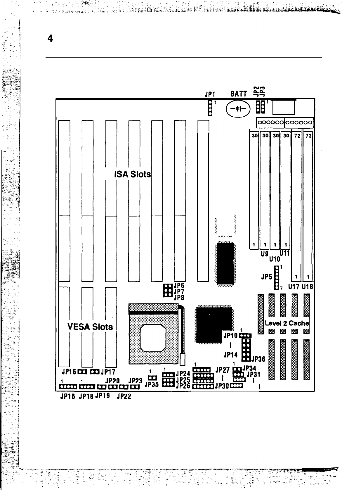
Chapter
1.
Mainboard
Layout
.%~.f*...*...*..
::
::
::
::
::
::
::
-I
2
.l
::
::
3
::
::
(
::
.
3
2:
U8
Figure
1-1.
Mainboard
JP33
Layout
Page 9

-Chapter 2
Hardware Configuration
Before you install the 80486 mainboard into the system
chassis, you may find it convenient to first configure the
mainboard’s hardware. This chapter describes setting jumpers,
installing memory modules, and attaching components.
Power Precautions
Before you begin configuration, make sure you are working
with an unplugged mainboard. Many components are powered
by low-voltage current, but there still may be a dangerous
electric current coming from the leads and power supply. Take
the following precautions:
Turn off the power supply, and unplug the power cord
before you begin.
l
Unplug all cables that connect the mainboard to any
external devices.
Jumper Switch Settings
You can configure hardware options by setting jumper switches
on the mainboard. See Figure 1-l for jumper locations. Set a
jumper switch as follows:
Short a jumper by placing the plastic jumper cap over
two pins of the jumper.
the pins of a jumper by removing the jumper cap.
Page 10

6
Chapter 2
Note: When you open the jumper, attach the plastic jumper cap to
of
one
the pins so you don’t lose it.
For setting 3-pin jumpers, the symbols below are used:
l-2
2-3
Pins 1 and 2 are Shorted with a jumper cap.
Pins 2 and 3 are Shorted with a jumper cap.
For setting 2-pin jumpers, the following symbols are used:
ON
The jumper is Shorted (ON) when the jumper
cap is placed over the two pins of the jumper.
OFF
jumper is Open
(OFF)
when the jumper cap
The
is taken off of the jumper.
JP3 - Flash ROM VPP Supply Selector
JP3 is the Flash ROM Program Voltage selector.
Description
5 volt
12 volt
JP3
l-2
2-3
Page 11
Hardware Configuration
7
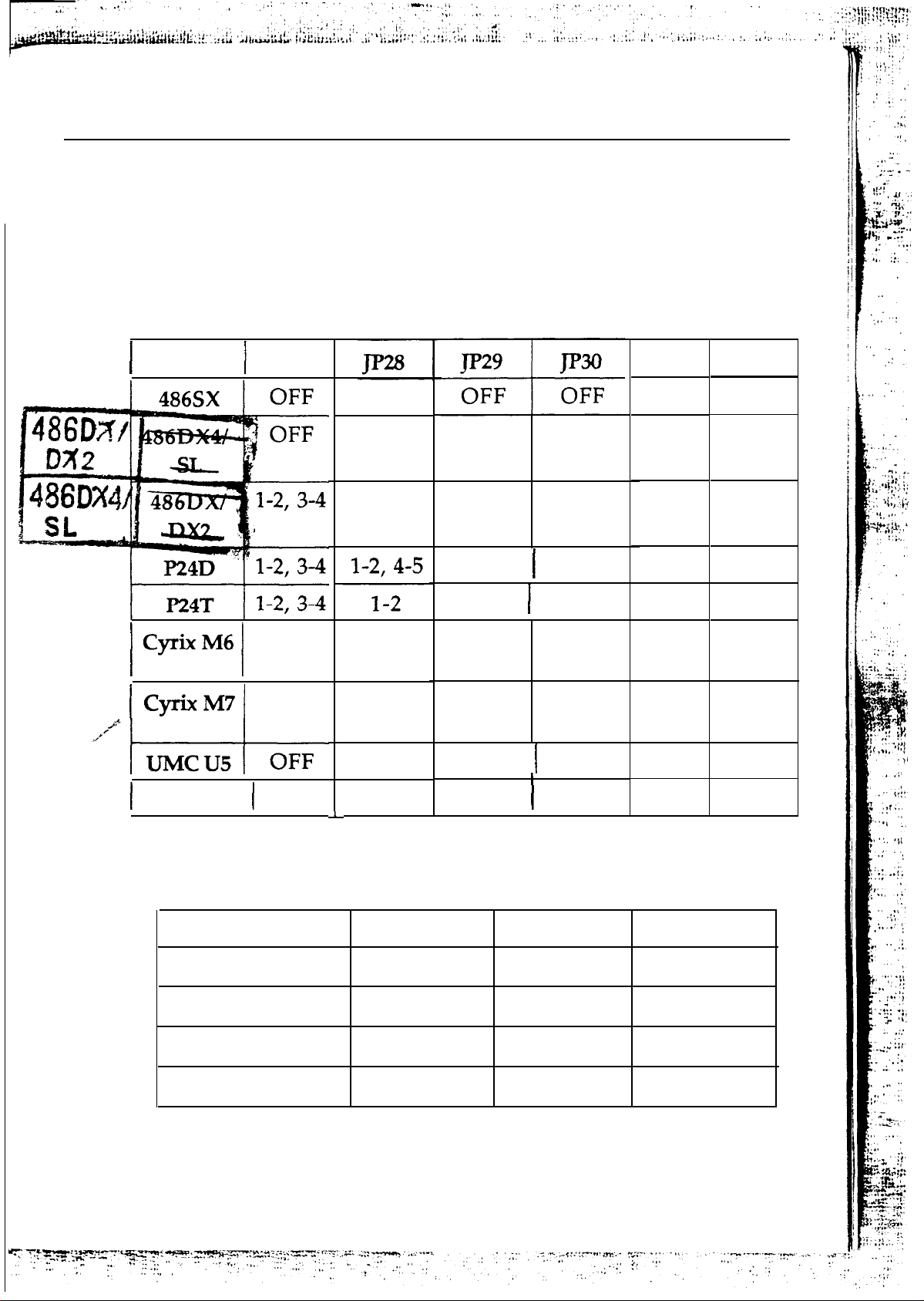
JP27-JP30,
Set
jumpers
JP32,
JP33-
CPU Type Jumpers
JP27-JP30, JP32, and
JP33 so that the
recognizes the type of CPU installed. Set CPU type
Note:
A wrong setting may cause the system to hang up.
Jumper JP27
2-3
2-3
l-2
OFF
l-2
l-2, 4-5
l-2
OFF
5-6
3-4, 5-6
5-6
JP32
OFF
mainboard
as below.
JP33
1-2
1-2
1-2
2-3
l-2, 3-4
1-2, 3-4
l-2, 3-4
1-2, 3-4
2-3
AMD
JP6-JP8 -
CPU
25 MHz
33 MHz
40 MHz
2-3, 4-5
2-3
OFF
l-2, 3-4,
5-6
l-2, 3-4,
5-6
2-3
2-3
CPU Clock Setting
Clock
JP6
OFF
ON
OFF
l-2, 3-4, l-2, 3-4,
5-6
l-2, 3-4, 2-3, 4-5
5-6
2-3
OFF
5-6
l-2
OFF
JP7
OFF
ON
ON ON
OFF
l-2 l-2, 3-4
3-4 2-3
l-2 l-2, 3-4
JP8
2-3
ON
ON
50
MHz
ON
OFF
OFF
Page 12
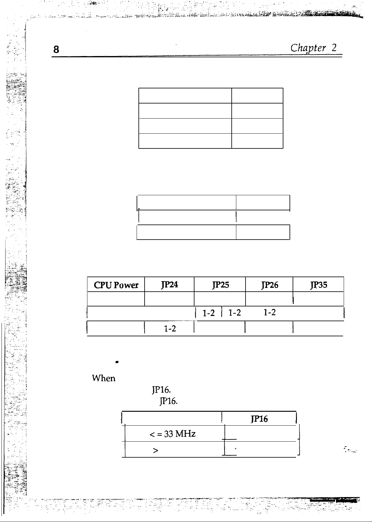
JP31-
Intel
80486DX4
CPU Clock Multiplier Jumper
JP34-
AMD
Clock Multiplier
3x
2.5 X
2x
80486DX4
Clock Multiplier
CPU Clock Multiplier Jumper
3x
2x
JP31
OFF
1-2
2-3
JP34
OFF .
ON
JP21-JP24, JP35 - CPU Power Selectors
5 Volts
3.3 Volt
4 Volts
JP16
jumper OFF of
put a jumper ON
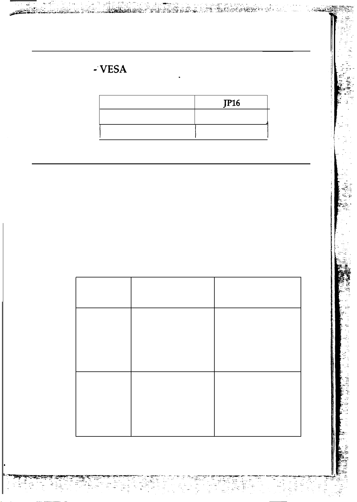
VESA Clock Selector
2-3
en the CPU clock is greater than 33 MHz
Wh
Description
33 MHz
2-3
1-2
2-3
I
1-2
OFF
ON
OFF
I ON
OFF
I
Page 13
Hardware Configuration
9
JP17
JP17 sets the VESA wait state.
Wait State
Description
OWS
1
ws
Memory Configuration
The DRAM sub-system contains 4 banks. Four 30-pin SIMM
sockets
bank 1 and 3; Ul8 is bank 0 and 2.
You can not install 30-pin SIMM if you use 2-bank type DRAM
U8-U11
are bank 2; two 72-pin SIMM sockets U17 is
OFF
ON
in
U18,
but you can install 30-pin SIMM if you use l-bank type
DRAM in
U8-U11
BANK
Installed
U18.
2
None
U18
BANK 0,2
l-bank type DRAM
or
None
2-bank type DRAM
or
l-bank type DRAM
or
U17
BANK 1,3
2-bank type DRAM
or
l-bank type DRAM
or
None
2-bank type DRAM
or
l-bank type DRAM
or
None
None
Page 14
Chapter 3
Mainboard Installation
Once you have configured the 80486 Deep Green mainboard’s
hardware, you are ready to install the mainboard into the
system chassis This chapter describes what you need to
assemble an advanced computer system based on the 80486
mainboard.
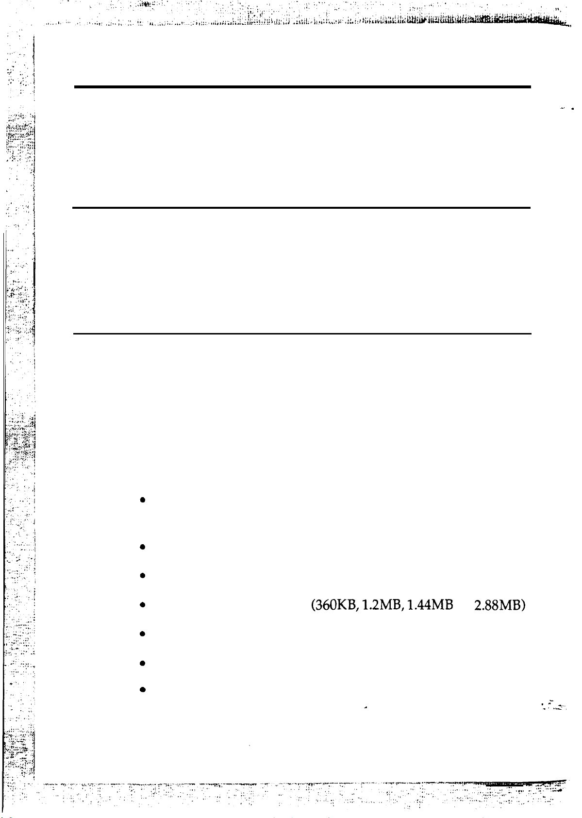
What You Need
The following components and tools are the minimum required
to build a working computer system.
Components
The following components are recommended:
Case with standard chassis and hardware. The 80486
fits most AT compatible cases.
Standard AT power supply
8 ohm speaker
Floppy disk drive(s)
Hard disk drive (optional)
Hard disk and floppy disk drive controller card
or
Flat
and
ribbon cables to connect the disk drive controller
the disk drive(s)
Page 15
11
l
Serial /parallel interface card
AT-compatible keyboard
Video card and Display (monochrome, CGA, EGA, or
VGA)
Tools
Installing the 80486 mainboard requires the following tools:
Nutdriver
3
You can also use a Phillips screwdriver with a 6-inch shaft
and a flat blade screwdriver instead of the nutdrivers.
Nutdriver
Power Supply Requirements
You need a clean, steady power source to get the best
performance from your system. For reliable performance, make
sure your power supply provides a voltage range of 5.25 volts
maximum to 4.75 volts minimum. If your area has noisy power
transmission, use a line noise filter between the power source
and your computer.
You must make sure the power supply can supply the total
power required by all the devices in your system. Check the
power requirements of the floppy disk drives, hard disk
drives, and any additional boards that you will use. In a
system that includes a hard disk drive and installed adapter
cards, use a power supply of at least 180 watts.
Page 16

‘1 2
Installing the Mainboard
Before you begin, check the location of the mounting holes in
the case and on the mainboard.
Caution: Static electricity can damage the mainboard.
Install the 80486 mainboard as follows:
Review the section on static electricity precautions at
the beginning of this manual.
Chapter 3
2.
Place the case on an anti-static mat and remove the
cover. Remove the nylon stand-offs and screws for
mounting the mainboard.
3.
Put the front of the case to your right and the rear to
your left. The mainboard occupies the section of the case
nearest you; the power supply goes on the far side.
4.
Align the mounting holes on the case to the mounting
holes on the mainboard. Make sure you can access the
5.
keyboard connector
From the bottom of the mainboard, insert stand-offs into
once the board is installed.
the proper holes on the board, and attach the mounting
screws to the bottom of the case.
Note: Some cases do not use stand-o@ and mounting screws; in this
case you can fasten the mainboard into the case with regular
screws.
6.
Place the mainboard
securely with regular
into the case and fasten the board
screws.
Page 17
Main board Ins
tion
13
Connecting
Once you have fastened the mainboard into the system case,
the next step is to connect the internal cables. The internal
cables are wire leads with plastic female connectors that
attach to the connectors. The mainboard connectors have
varying numbers of pins and are the points of contact between
the mainboard and other parts of the computer.
Note: Before making connections on the board, make sure that power
to the system is turned
Mainboard
Connectors
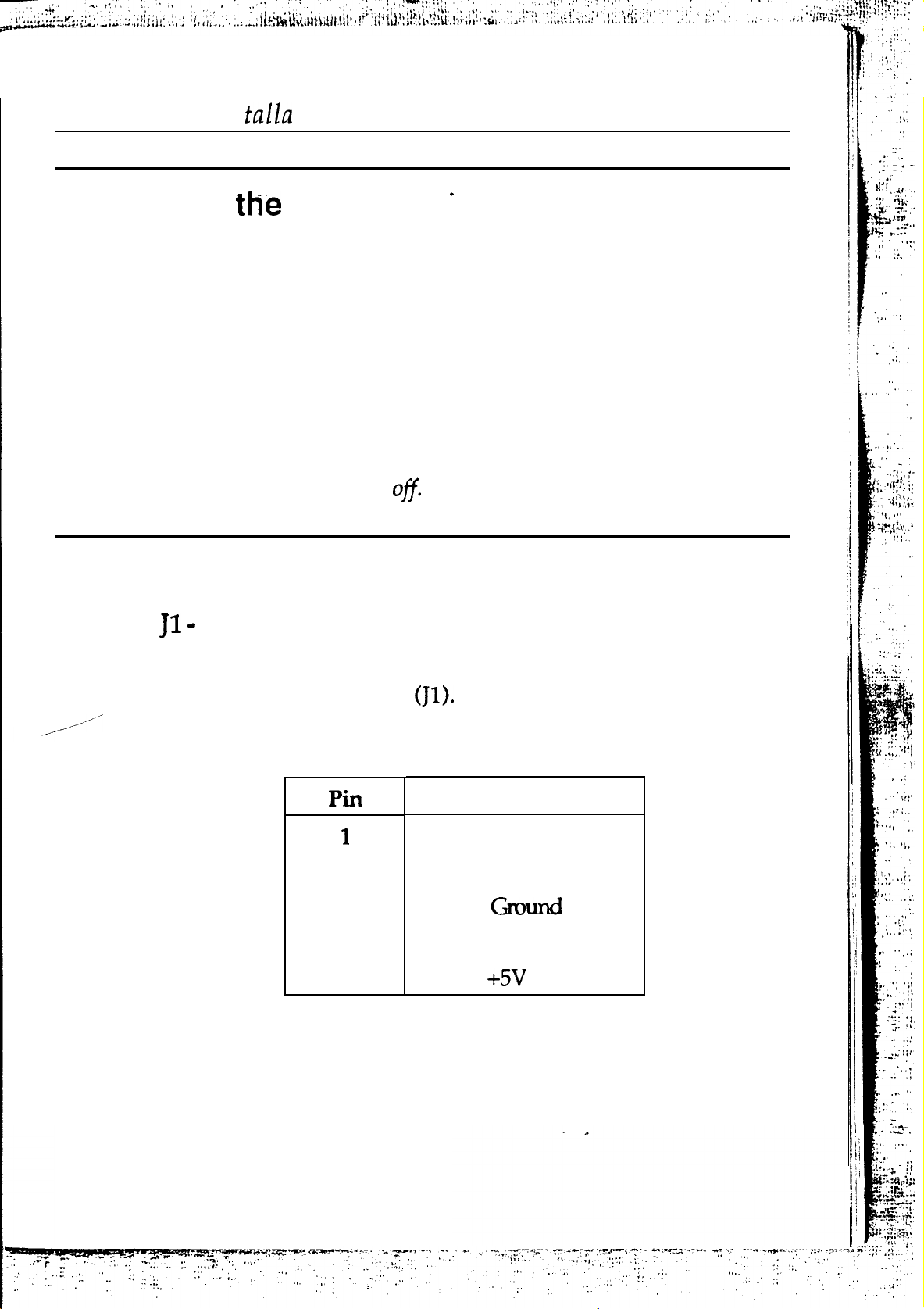
Keyboard Connector
A standard five-pin female DIN keyboard connector is located
at the rear of the board
cable into this connector.
2
3
4
5
Plug the jack on the keyboard
Description
Keyboard Clock
Keyboard Data
Ground
DC
Page 18
14
Chapter 3
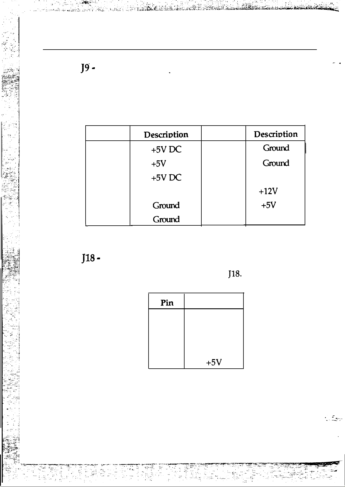
Power Supply Connectors
The power supply connector has two six-pin male header
connectors. Plug the dual connectors from the power directly
onto the board connectors.
Pin
12
11
10
9
-5v Ix
8
7
Speaker Connector
Pin
6
5
4
3
2
1
Attach the system speaker to connector
Description
-12v DC
DC
Power Good
2
3
4
1
Data Out
Not Used
Ground
Page 19
Mainboard Installation
External Battery
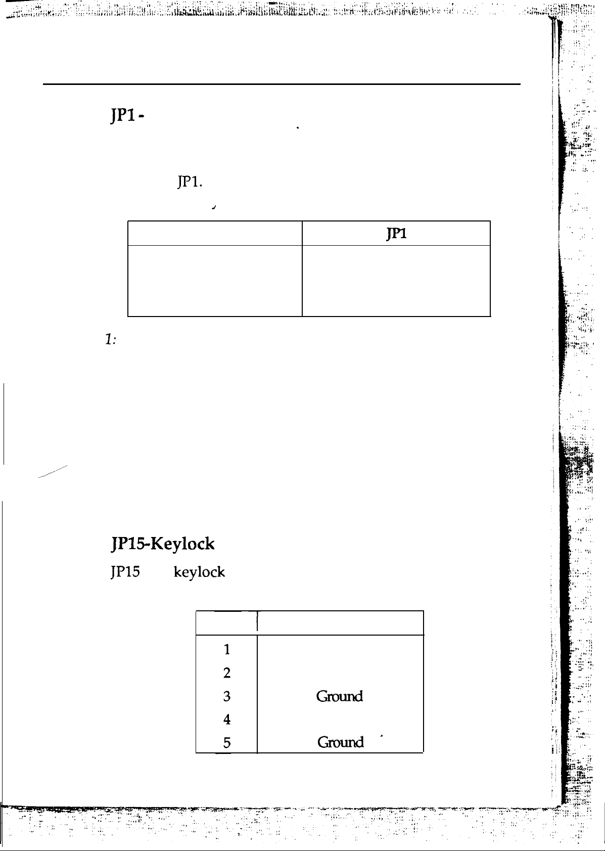
The 80486 mainboard has a non-rechargeable lithium battery
on-board; however, you can also attach an external battery to
connector JPl. Using an external battery helps you conserve the
on-board batterv.
Description
15
Note
Note 2:
External Battery
Internal Battery
Clear CMOS
1-4
2-3
3-4
The factory default setting has a jumper cap on pins 3-4 to
avoid losing battery power during shipping. For an
installed internal battery, place a jumper cap on pins 2-3.
When you install an external battery, remove this jumper
cap.
To clear the
pins 34 and
CMOS configuration, place a jumper cap on
then place the cap back on pins 2-3 for normal
operation.
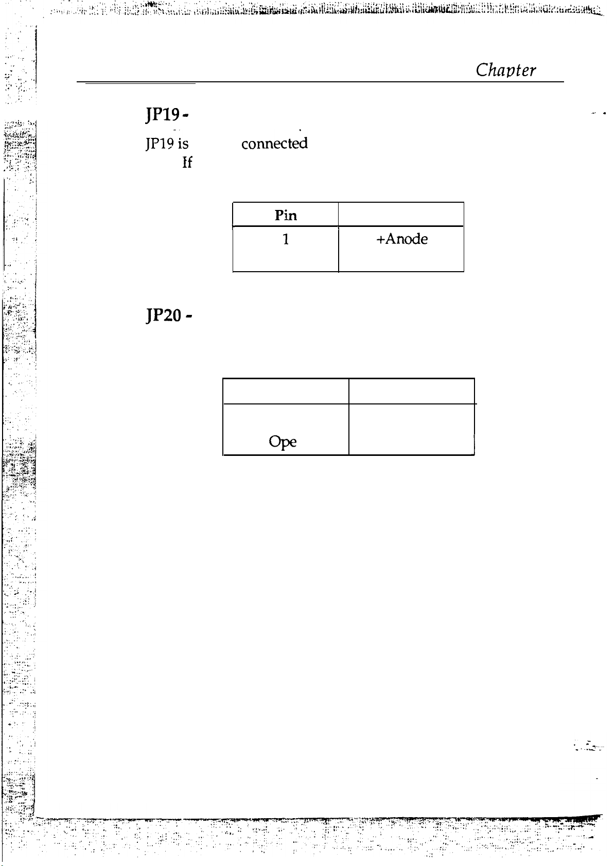
& Power LED Connector
keyboard and the Power-LED on the case.
Pin
Description
LED power
Not Used
Keyboard Inhibiter
’
Page 20
16
3
Turbo LED Connector
usually connecteh to a Turbo LED on front of the system
case.
lights during high-speed operation.
Attach
switch restarts the system.
the system board select is in Turbo mode, the indicator
Description
2
Reset Switch Connector
the Reset switch cable to this connector. The Reset
Setting
-Cathode
Description
Short
n
Reset
1
Not Reset
Page 21
Mainboard Installation
Switch Connector
JP22 connects to the Turbo switch, which is used to select the
mainboard’s clock speed.
Setting
n
Short
In addition to switching clock speed using hardware control
via the turbo switch, you can also switch the clock speed using
software control via keyboard
The keyboard commands are as follows:
CTRL, ALT, [+]
CTRL, ALT,
Note that hardware control and software control are
Press these three keys simultaneously
to select Turbo Mode.
Press these three keys simultaneously
to select Low Speed Mode.
Description
Turbo Mode
Low speed Mode
alternately activated.
control from hardware control, and vice versa, the system must
be in High Speed Mode.
JP23
A push button attached to this connector lets you force the
system to enter suspend mode.
Suspend Switch Connector
Before you can activate software
Page 22

18
System Assembly Overview
After you have installed and connected the mainboard,
assemble components in the following order:
Power Supply: Place the power supply so that it fits the
raised tongues on the chassis floor. Insert and fasten the
two screws on the back panel of the chassis. Connect the
power supply to the power supply connectors,
Chapter 3
2.
Disk Drives: Slide the disk drives into the chassis.
Connect a wide 34-wire ribbon cable to each disk drive;
this cable will attach to an adapter card. The power
supply has four cables, each with four wires. Connect
these cables to the disk drives.
3.
Adapter Cards:
Insert each adapter card
Disk
Controller cards, Video card, Serial/Parallel Interface
card, etc.
according to the configuration instructions
that come with the card. Connect the disk drives to the
Floppy Disk and Hard Disk Controller cards.
4. Keyboard: Connect the keyboard to its connector,
5.
Display: Connect the display cable to the Video Card,
and the display’s power cord into a power outlet.
6.
Connect the power cord to
Case: Slide on the case cover and fasten its screws.
the
power supply and plug it into a
wall outlet. Put your boot disk into drive A: and turn on the
power. You will then need to run the BIOS setup program.
Page 23
Chapter
Setup
This chapter explains how to configure the mainboard’s BIOS
setup program.
mainboard is either the Award BIOS from Award Software
Inc., or the AM1
After you have configured the mainboard, and have
assembled the components, you can turn on the completed
system. At this point, run the software setup to ensure that the
system information is correct.
The software setup of the system board is achieved through
Basic Input-Output System (BIOS) programming. You use the
BIOS setup program to tell the operating system what type of
devices are connected to your system board.
The system setup is also called CMOS setup. Normally, you
need to run system setup if either the hardware is not
identical with information contained in the CMOS RAM, or if
The setup program provided with the
from American Megatrends Inc.
the CMOS RAM has lost power.
Page 24
Award-
Enter the Award Setup program’s Main Menu as follows:
Setup
Turn on or reboot the system. The following message
appears at the bottom of the screen:
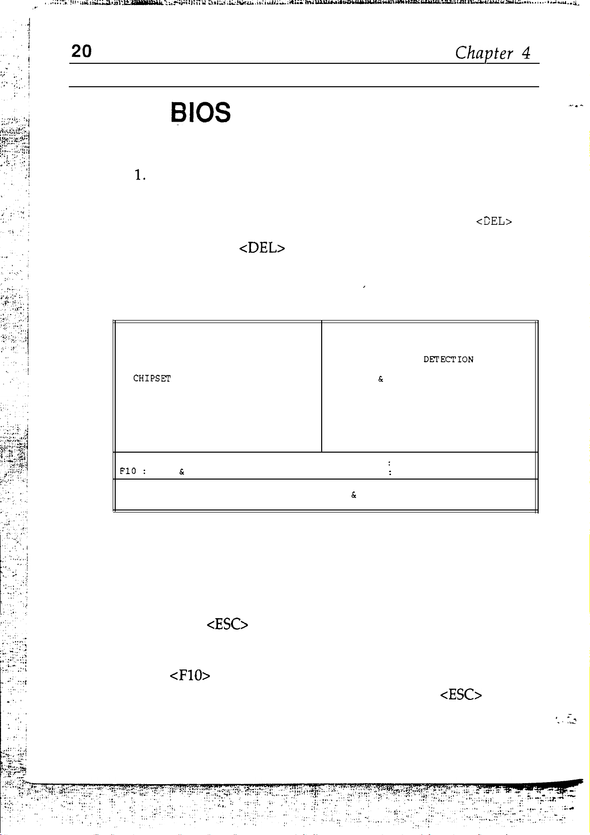
"TO ENTER SETUP BEFORE BOOT PRESS CTRL-ALT-ESC or
2.
Press the
key to enter the Award BIOS setup
program and the following screen appears:
ROM ISA BIOS
CMOS SETUP UTILITY
AWARD SOFTWARE, INC.
STANDARD CMOS SETUP
BIOS FEATURES SETUP
FEATURES SETUP
POWER MANAGEMENT SETUP
LOAD BIOS DEFAULTS
LOAD SETUP DEFAULTS
Esc
: Quit
Save
Exit Setup
Save Data to CMOS
PASSWORD SETTING
IDE HDD AUTO
SAVE
EXIT WITHOUT SAVING
t-+44-
(Shift) F2
EXIT SETUP
Select Item
Change Color
Exit SETUP
KEY"
3.
4.
5.
Choose an option and press <Enter>. Modify the system
parameters to reflect the options installed in the
system. (See the following sections for more
information.)
Press
at anytime to return to the Main Menu.
In the Main Menu, choose “SAVE AND EXIT SETUP” or
to save your changes and reboot the system.
Choosing “EXIT
WITHOUT
SAVING“ or
ignores
your changes and exits the program.
Page 25
Award BIOS Setup
21
Main Menu Options
The Main Menu options of the Award BIOS are as below.
STANDARD CMOS SETUP
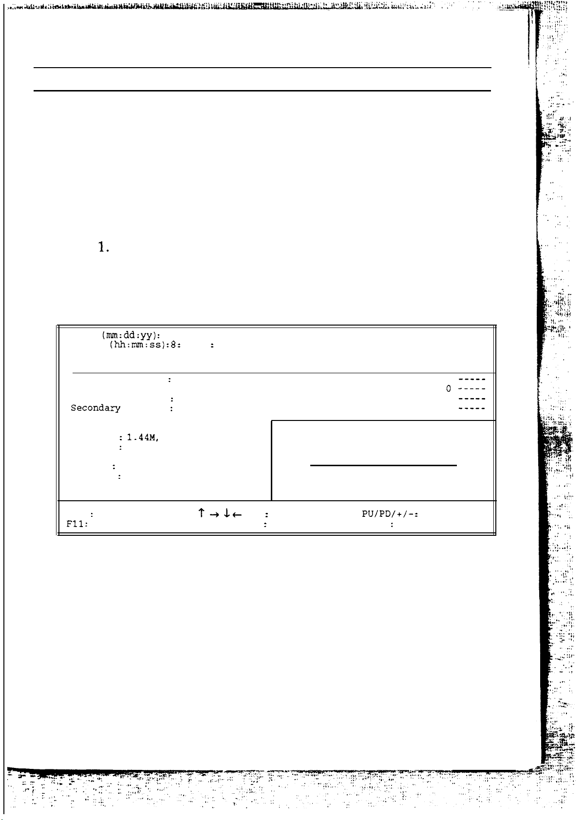
Run the Standard CMOS Setup as follows.
Choose “STANDARD CMOS SETUP” from the Main
Menu and a screen with a list of items appears.
CMOS SETUP Utility
AWARD SOFTWARE, INC.
Date
Time
HARD DISKS
Primary Master
Primary Slave
Secondary Master
Slave
Fri,Feb 10 1995
16
TYPE
None
: None
None
None
24
SIZE CYLS HEAD PRECOMP LANDZ SECTOR MODE
.
ROM ISA BIOS
0 0
0 0 0
0 0
0
0
0 0
0
0
0 0
0
0
0
0
0
0
0
0
Drive A
Drive B
Video
Halt On
Esc
Quit
Help
2.
None
EGA/VGA
All Errors
3.5 in.
(Shift) F2
Base Memory: 640K
Extended Memory:
Other Memory: 384K
Total Memory:
Select Item
Change Color
15360K
16384K
Modify
F3
Toggle Calendar
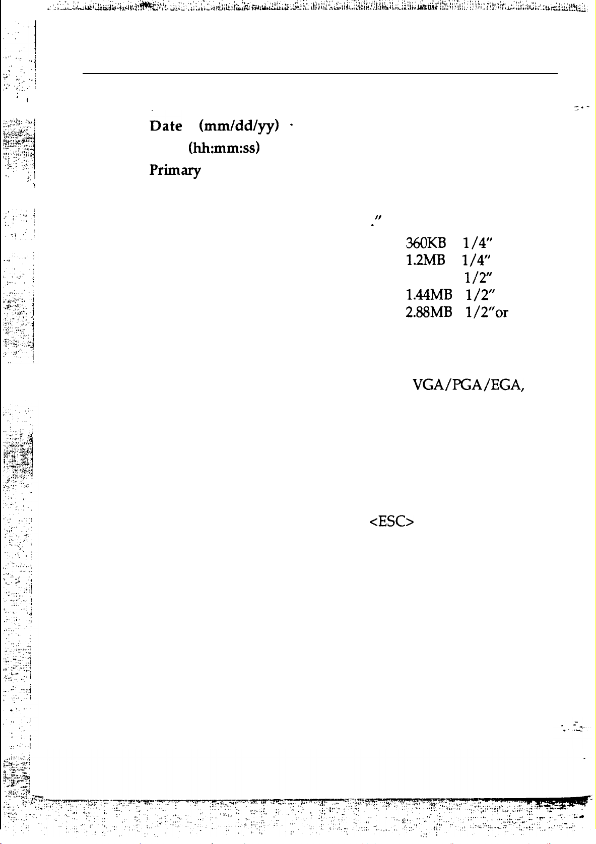
Use the arrow keys to move between items and to select
values. Modify the selected fields using the
PgUp/PgDn/+/- keys. Some fields let you enter numeric
values directly.
Page 26
22
Chapter 4
Time
& Secondary
IDE
Type the current date
Type the current time
Choose from the standard hard disk
types 1 to 46, type 47 is user defined. If a
hard disk is not installed choose “Not
installed
DriveA&B
Choose
5
5
72OKB 3
3 l/2”
3
Not installed
Video
Choose Monochrome,
Color 40x25,
Color 80x25, or
Not installed
Halt On
3.
After you have
Setup program, press the
Main Menu.
This item determines whether the
computer stops if an error is detected
during power up.
finished with the Standard CMOS
key to return to the
Page 27
Award BIOS
BIOS FEATURES SETUP
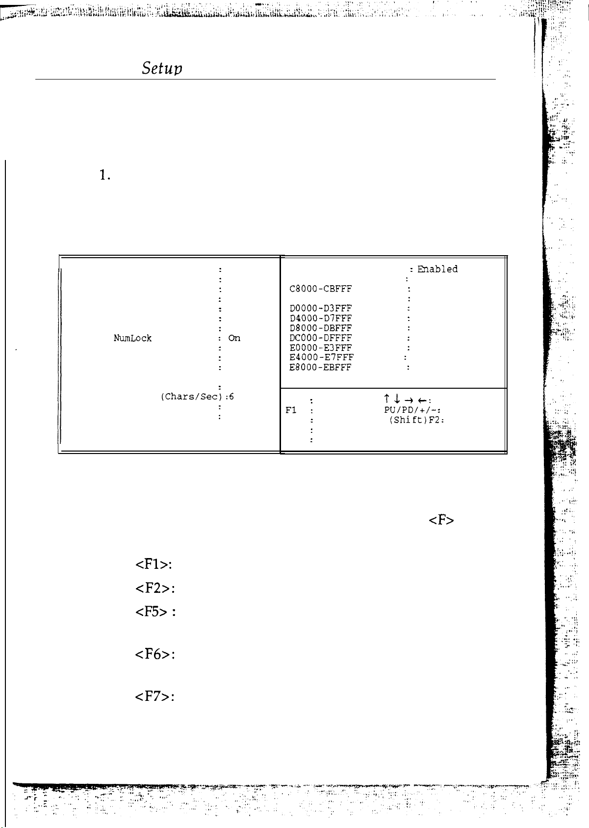
Run the BIOS Features Setup as follows.
Choose “BIOS FEATURES SETUP” from the Main Menu
and a screen with a list of items appears.
23
ROM ISA BIOS
BIOS FEATURES SETUP
AWARD SOFTWARE, INC.
Virus Warning
CPU Internal Cache
External Cache
Quick Power On Self Test
Boot Sequence
Swap Floppy Drive
Boot Up Floppy Seek
Boot Up
Boot Up System Speed
IDE HDD Block Mode
Gate A20 Option
Typematic Rate Setting
Typematic Rate
Typematic Delay (Msec)
Security Option
2.
Status
Use the arrow keys to move between items and to select
values.
Disabled
Enabled
Enabled
Enabled
C,A
Disabled
Disabled
High
Disabled
Fast
Disabled
250
Setup
Modify the selected fields using the
PgUp/PgDn/+/- keys. An explanation of cF> keys
follows:
System BIOS Shadow
Video
CCOOO-CFFFF Shadow
ESC
F5
F6
F7
BIOS Shadow
Shadow
Shadow
Shadow
Shadow
Shadow
Shadow
Shadow
Shadow
Quit
Help
Old Values
Load BIOS Defaults
Load Setup Defaults
Enabled
Disabled
Disabled
Disabled
Disabled
Disabled
Disabled
Disabled
Disabled
Disabled
t: Select Iter
Modify
Color
“Help” gives options available for each item.
Change color
Get the old values. The user started the
current session with these values.
Load all options in the BIOS Features Setup
with the BIOS Default values.
Load all options in the BIOS Features Setup
with the Setup Default values.
Page 28

Chapter 4
: :
A short description of the screen items follows:
Virus Warning
Choose Enabled or Disabled. Enable this
option and a SYSTEM WARNING MESSAGE
appears when the system detects a virus.
CPU Internal
Cache
External Cache
Choose Enabled or Disabled. This option lets
you enable the CPU’s internal cache memory.
Choose Enabled or Disabled. This option lets
you enable the external cache memory. For
better performance, make sure you always
choose “Enabled.” .
Quick Power On
Self Test
Boot Sequence
a fast POST and boot-up speed.
The default setting first attempts to boot from
Enabled or Disabled. Enabled provides
drive A: and then from hard disk C:. You can
^I.-
Swap Floppy
Driver
Boot Up Floppy
Seek
Boot Up Num
Lock status
Boot Up System
Speed
Block
Mode
reverse this sequence with “C: A:“, but then
drive A: cannot boot directly.
Choose Enabled or Disabled. When Enabled
Floppy drives A
B are swapped under DOS.
Choose Enabled or Disabled. “Disabled”
provides a fast boot and reduces the possibility
of damage to the heads.
Choose On or Off.
puts numeric keypad in
Num Lock mode at boot-up. Off puts this
keypad in arrow key mode at boot-up.
Choose High (default) or Low. This option lets
you choose system
speed.
Choose Enabled or Disabled. If your IDE HDD
supports BLOCK MOVE MODE, then you can
Enable this function to speed up the HDD
Access time. If not, please Disable this function”
to avoid an HDD Access Error.
Page 29
..I.‘
i
Gate
Option
Typematic Rate
Setting
Typematic Rate
Typematic
Delay
Security Option
Choose Fast or Normal. This item lets you use
the GA20 from the
or the keyboard
controller.
Choose Enabled or Disabled. Enable this
option to adjust the keystroke repeat rate.
Choose the rate a character keeps repeating.
Choose how long after you press a key that a
character begins repeating.
Choose Setup, or System. Use this feature to
prevent unauthorized system boot-up or
unauthorized use of BIOS Setup.
Each time the system boots
the password prompt appears.
Video BIOS
Shadow
3.
After you have finished with the BIOS Features Setup
program, press the
instructions to save or disregard your settings.
Password prompt only
appears if you attempt to
enter the Setup program.
BIOS shadow copies BIOS code from slower
ROM to faster RAM. BIOS can then execute
from RAM. These
segments can be
shadowed from ROM to RAM. BIOS is
shadowed in a
segment if it is enabled and
it has BIOS present.
key and then follow screen
Page 30
26
CHIP-SET FEATURES SETUP
Chapter 4
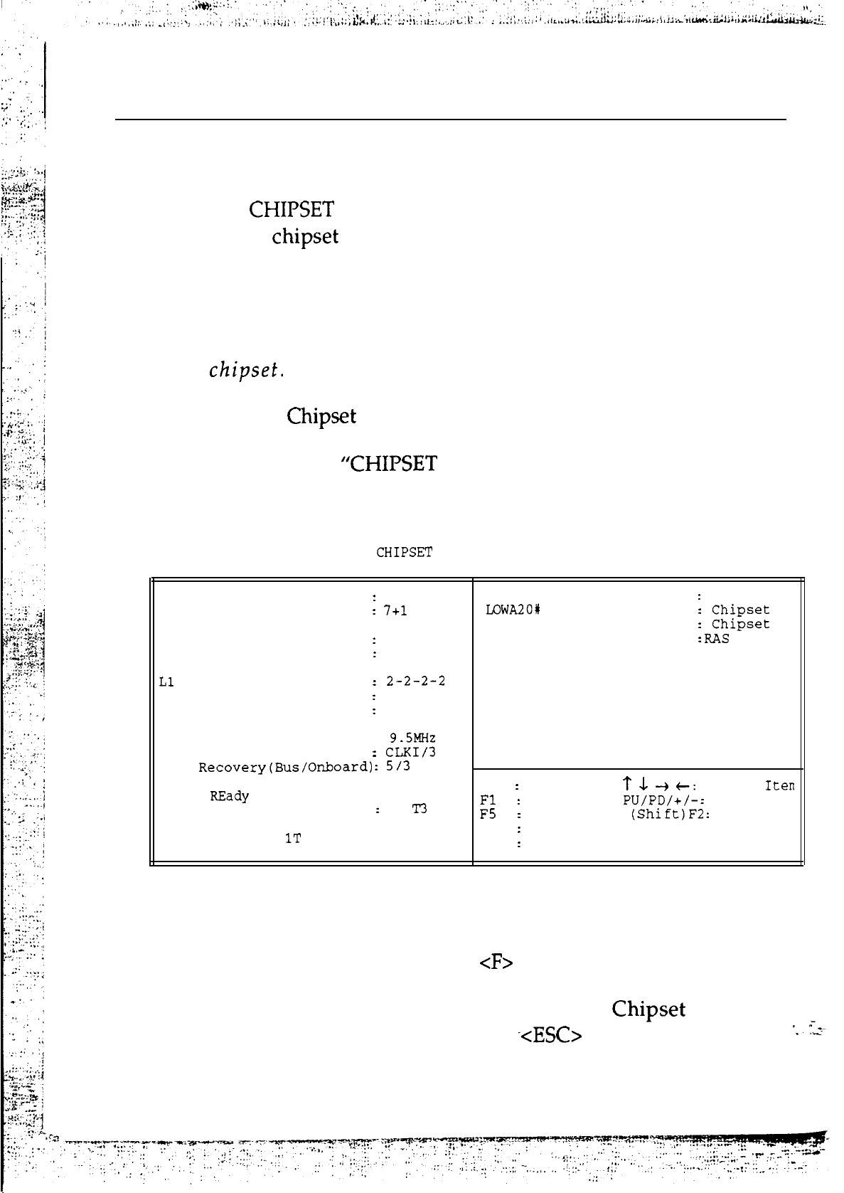
The
of the
FEATURES SETUP is used to control the values
registers. These registers control most of the
system options in the computer.
‘Note: The Default settings shown below are the optimum settings.
Change these settings only if you are familiar with the
Run the
1.
Choose
Features Setup as follows.
FEATURES SETUP” from the Main
Menu and a screen with a list of items appears.
ROM ISA BIOS
AWARD SOFTWARE, INC.
Auto Configuration
Alt Bit in Tag SRAM
DRAM Wait State Select
DRAM Page Mode
L2 Cache Read Wait State
L2 Cache Write Wait State: Wr-Back
Cache Update Scheme
System BIOS Cacheable
Video BIOS Cacheable
Enabled
: 0 WS
Normal
Wr-Back
Disabled
Disabled
FEATURES SETUP
ISA Bus Refresh Mode
Bits
RC Reset Select
DRAM Refresh Method
Select
Fast
Only
Keyboard Controller Clock:
ISA Bus Clock Option
I/O
Local
Signal LDEV# Sample Time
CPU ADS# Delay
Delay Setting: 0 WS
or Not : No Delay
2.
Use the arrow keys to move between items and to select
values.
In
Modify the selected fields using the
PgUp/PgDn/+/- keys.
3.
After
Setup
screen
you have finished with the Chipset Features
program, press the
instructions to save or disregard your settings.
ESC
Quit
Help
Old Values
F6
Load BIOS Defaults
F7
Load Setup Defaults
t: Select
keys are explained below:
key and then follow
Modify
Color
Page 31
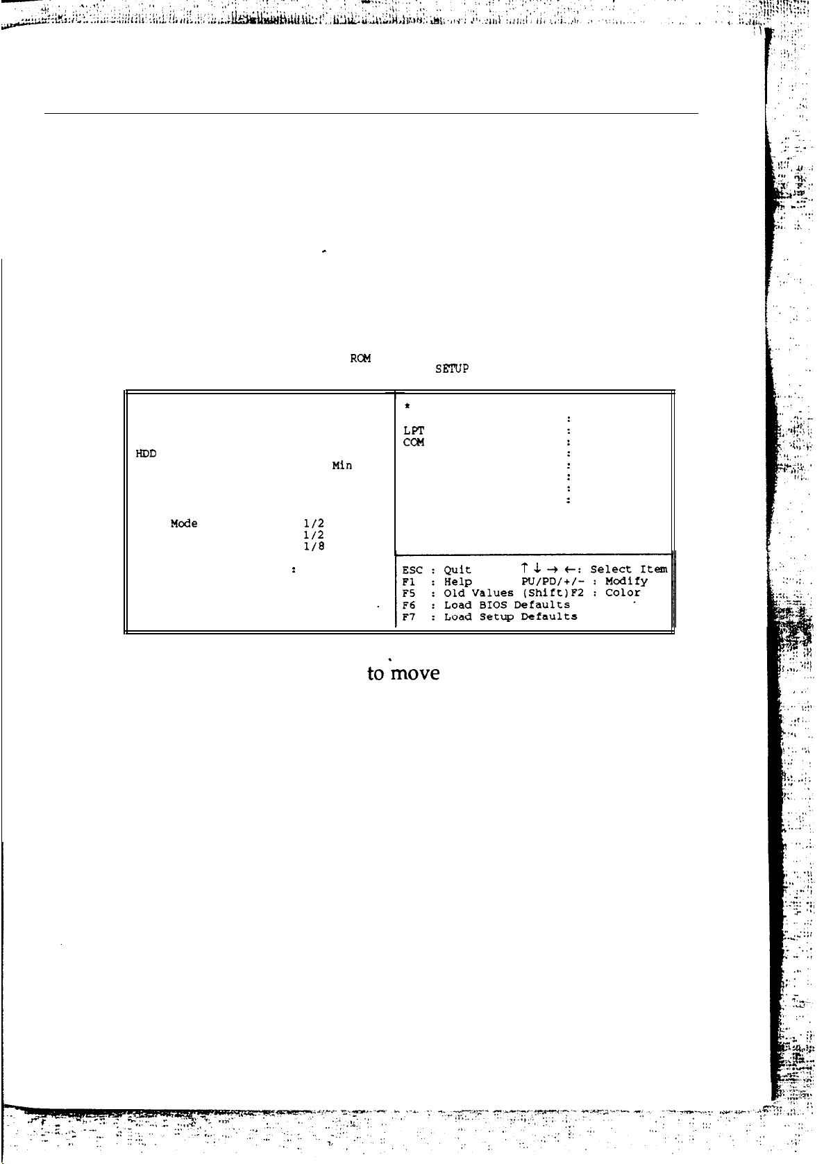
Award BIOS Setup
27
POWER MANAGEMENT SETUP
.
The Power Management Setup option sets the system’s power
saving functions.
Run the Power Management Setup as follows.
1.
Choose “POWER MANAGEMENT SETUP” from the
Main Menu and a screen with a list of items appears.
ISA BIOS
Monitor Event In Full On Mode
VESA Slave Activity
Port Activity
Port Activity
ISA Master Activity
IDE Activity
Floppy Activity
VGA Activity
Keyboard Activity
Disabled
Enabled
Enabled
Enabled
Enabled
Enabled
Disabled
Enabled
Power Management
Video Off Method
Standby Timer
Doze Timer Select
Standby Timer Select
Inactive Timer Select
Control Item
Doze
Standby Mode Control
Inactive Mode Control
Suspend Switch Select
Control
POWER MANAGEMENT
AWARD SOFTWARE, INC.
User Defined
Blank Screen
Disabled
0.5
2 Min
2 Min
CPU CLK VGA
CLKI On
CLKI On
CLKI On
Enabled
2.
Use the arrow keys
values.
Modify the selected fields using the
between items and to select
PgUp/PgDn/+/- keys.
A short description of selected screen items follows:
Power Management This item controls the HDD power down,
system Doze, standby, suspend timer,
display ON/OFF and CPU clock feature.
There are five options:
User Define allows you to customize all
timer settings, define HDD and system
power management settings.
Optimize is the recommended setting.
Page 32
28
Chapter 4
Max Saving
is useful for testing and
demonstrating system’ performance.
Min
Saving
is minimized power saving.
Disable will turn off all BIOS power
saving functions on operating system.
Video Off Method
Select a method to protect the screen.
“Blank
only
makes your screen
blank but the display card still works
properly.
SYNC + Blank” not only
makes your screen blank, but also cuts off
the display card’s SYNC signal.
HDD Standby Time
Causes IDE HDD to “spin down” when not
accessed within a specified period. Disk
returns to full speed the next time it is
accessed. You can select from a range of “1
Min” to “15 Min” or “Disabled.”
Doze
Select
Mode Timer
Set a period of time after which no
activity causes the system to enter doze
mode from full-on mode. In this mode you
can control the CPU clock and the display
on/off from the control item below. You
can set a range of 0.5 to 512 min.
Note:
Doze mode. Green
Non-green
can only enter
can enter Doze,
Standby, and Inactive modes.
Standby Mode
Timer Select
Set a period of time after which no
activity causes the system to enter
standby mode from doze mode. In this
mode you can control the CPU clock and
the
on/off from the control item
below. You can set a range of 2 to 512 min.
Page 33

Award BIOS Setup
29
Inactive Mode
Timer Select
Mode Control Item
Set a period of time after which no
activity causes the system to enter
inactive mode from standby mode. In this
mode you can control the CPU clock and
the display on/off from the control item
below. You can set a range of 2 to 512 min.
This item sets the CPU clock and the
display on/off for every mode.
CLK can change the performance of
every mode. You can set from a range of
to
VGA can be turned on/of in every mode. If
you set VGA off in this mode, the display
is turned off.
Suspend Switch
Select
Monitor Even in
Full On Mode
3.
After you have finished with the Power Management
Setup, press the
Set suspend switch Enabled or Disabled.
Push this switch and you can enter
Inactive mode directly.
Enable those items you wish the BIOS to
monitor for activity. Activity on these
items cause the system to wake up and
work in Full-on mode.
LOAD BIOS DEFAULT
This Main Menu item loads the default BIOS values. These
settings are recommended for optimum performance. If the
key to return to the Main Menu.
CMOS is corrupted the defaults load automatically.
Page 34

30
LOAD SETUP DEFAULT
This Main Menu item loads the default system values. These
settings are recommended for optimum performance. If the
CMOS is corrupted the defaults load automatically.
PASSWORD SETTING
Chapter 4
This
password is required every time the system boots or an attempt
is made to enter the Setup program. The password cannot be
longer than 8 characters.
Important:
forget or lose the password, the only way to access the system
is to discharge CMOS memory using jumper JP1.
IDE HDD AUTO
If your system has an IDE hard drive, you can use this utility
to detect its parameters and automatically enter them into the
Standard CMOS Setup.
Main Menu item lets you configure the system so that a
Keep a safe record of the new password. If you
DETECTION
SAVE & EXIT SETUP
Select this item from the main menu and type "Y” to save the
values entered during the current session and then exit the
BIOS Setup program. Type “N” to return to the Setup program.
EXIT WITHOUT SAVING
Select this item from the main menu and type
BIOS Setup program without saving the values entered during
to exit the
Page 35
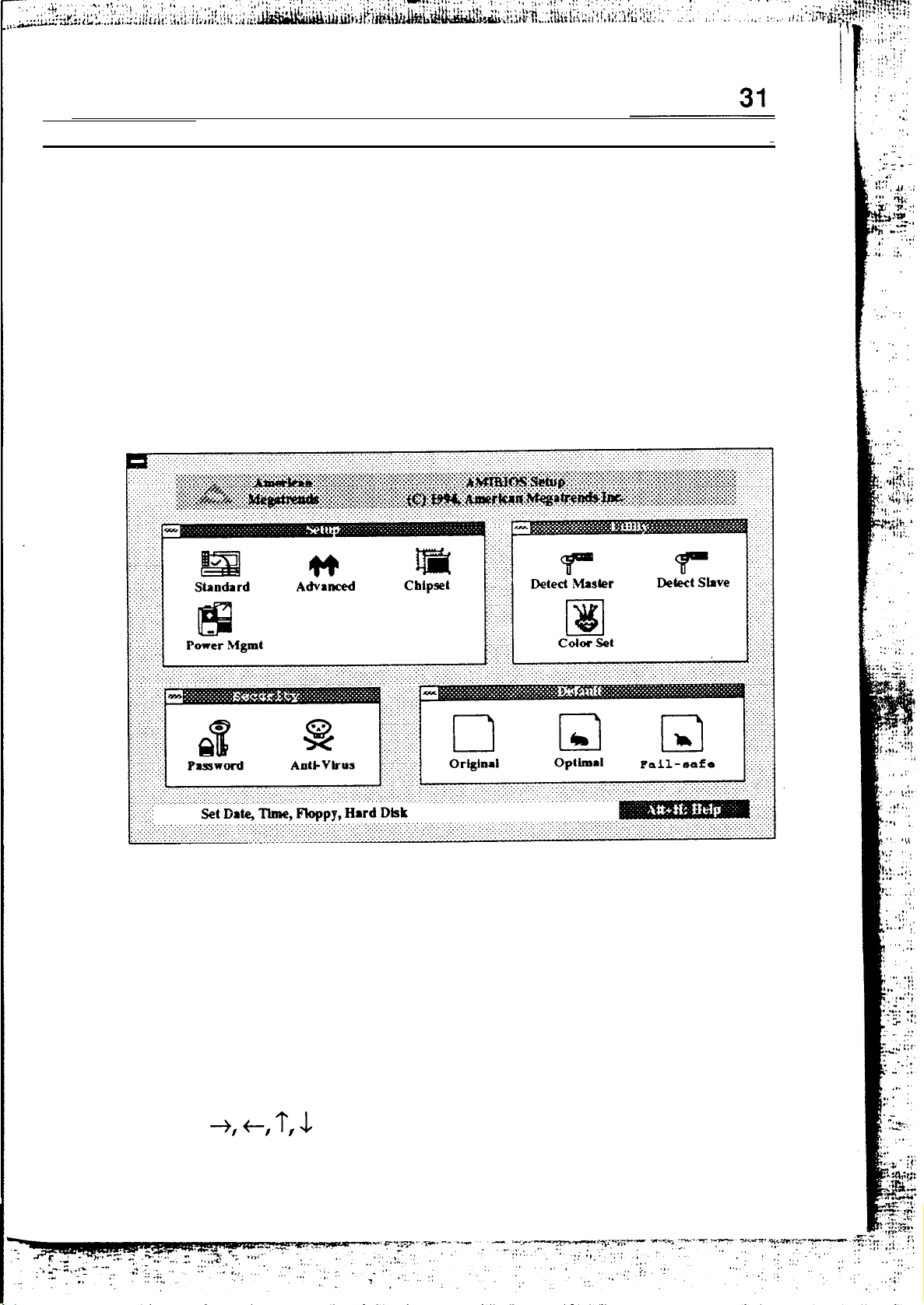
AMI WinBIOS
Setup
AMI
WinBIOS Setup
To enter the WinBIOS Setup program:
1.
2.
Turn on or reboot the system. A screen appears with a
series of diagnostic checks.
When “Hit <DEL> if you want to run SETUP” appears,
press the <DEL> key to enter the BIOS setup program.
The following screen appears:
3.
Choose options with the keyboard or mouse. Modify
settings to reflect system options. Press Alt-H for Help.
Using the Keyboard with WinBIOS Setup
If you choose options with a keyboard, use these keyboard
commands:
<TAB>
?,
<Enter>
Move to the next window or field.
Move to the next field, right, left, up, down.
Select in the current field.
Page 36
32
Chapter 4
<+>
<->
increment a value
Decrement a value.
Close the current operation and return to the
previous level.
<PgUp>
<PgDn>
<Home>
<End>
<Alt-H>
<Alt-Space>
Returns to previous page
Advances to next page.
Returns to the beginning of the text.
Advances to the end of the text.
Access a help window
Exit WinBIOS Setup.
Using a Mouse with WinBIOS Setup
To choose options with a Mouse, point the cursor at an item you
wish to modify and double-click the left mouse button. When
items appear, use the cursor to select values and press the left
mouse button to complete the changes. To leave the current
operation and return to the previous level, use the cursor to
press the exit box in the Window group’s upper left corner
WinBlOS
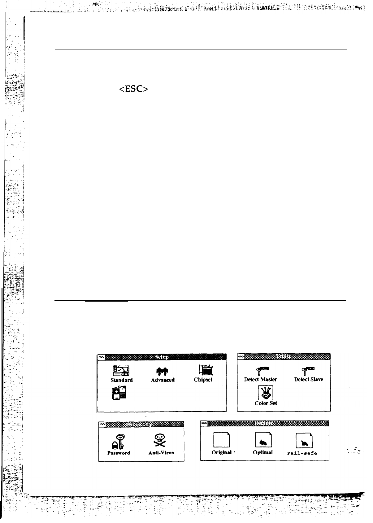
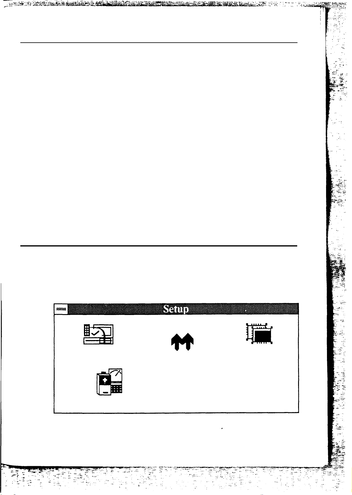
The WinBIOS Setup main menu has four windows: the Setup,
Utilities, Security and Default windows.
.
Setup Main Menu
Power Mgmt
Page 37
AMI WinBIOS
Setup
The Setup_ window has five icons that let you set system
configuration bptions such as date, time, hard disk type,
floppy type, and many others.
Utilities
This window has four icons that perform system functions.
Security
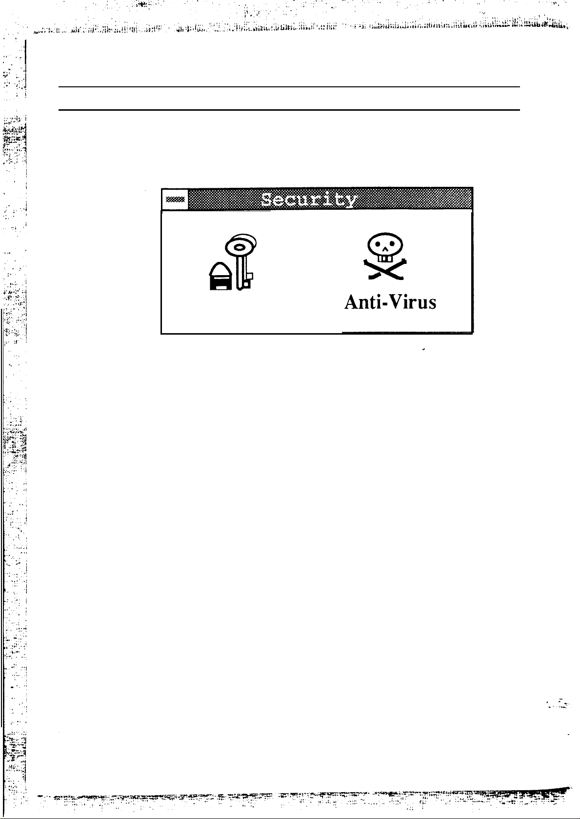
This window’s two icons control WinBIOS security features.
Default
This window’s three icons let you select default settings for all
Setup
33
WinBIOS Setup options. Choose the Optimal settings for best
performance characteristics.
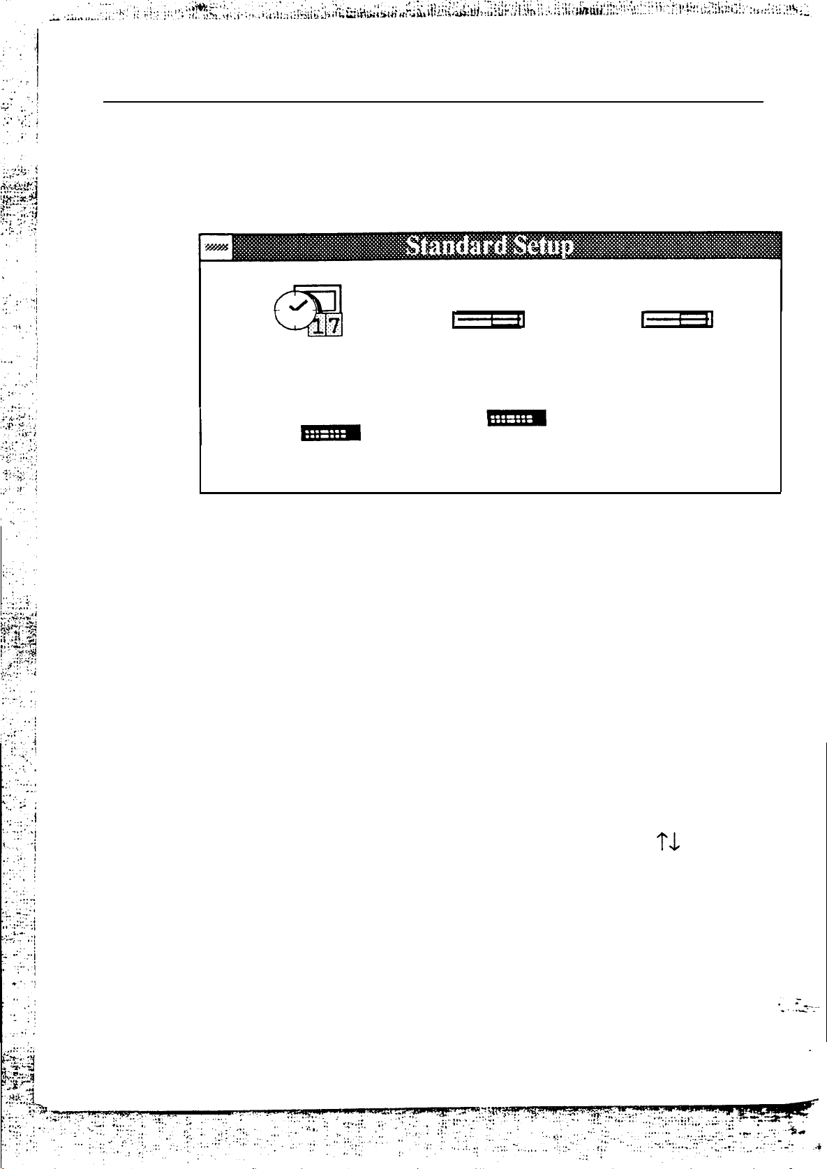
Setup Window
The Setup window has four icons that allow you to set system
configuration options.
Standard
Chipset
Advanced
Power Mgmt
Page 38
34
Chapter 4
Standard
Double-click on the Standard icon and the Standard Setup
screen appears:
Setup
Date/Time
Floppy A
Floppy B
Hard Disk D
Hard Disk
Select the icon of the items you wish to change, and modify
them using the keyboard or mouse.
C
Date/Time
Hard Disk
Hard Disk
Floppy Drive A:
Floppy
C:
D:
Drive
B:
Current values are displayed. Enter new
values using the keyboard.
A screen listing all valid disk types appears.
Select the correct type and press <Enter>. If
the hard disk is an IDE drive, go to the
Utility window of the main menu and select
Detect C: or Detect D: The
detects the IDE drive parameters, which
appear on the screen and then places them in
the Drive Type fields in the Standard Setup.
Select the floppy type with the
Settings are:
360 KB
1.2 MB
720 KB
5-1/4
5-l/4
3-l/2
WinBIOS auto-
keys.
inch
inch
inch
1.44 MB
2.88MB 3-l/2
3-1/2
inch
inch
Page 39

AMI WinBlOS Setup
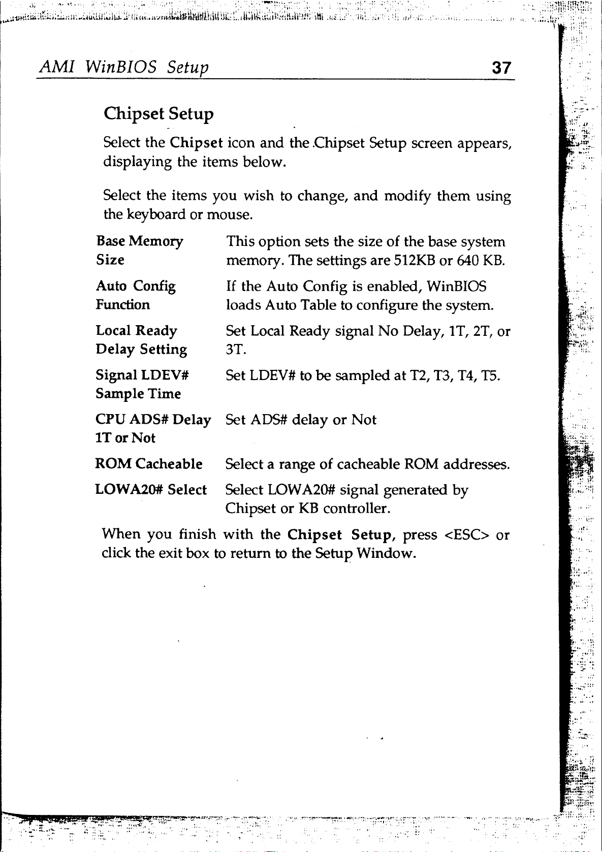
Advanced Setup
Double-click on the Advanced icon and the Advanced Setup
screen appears, displaying the items below. Select items you
wish to change, and modify them using the keyboard or mouse.
Typematic Rate
(Chars/Sec)
System
Primary Display
Above lM
Memory Test
Memory Test Tick
Keyboard
Typematic Rate sets the rate at which the
characters on the screen repeat when a key is
pressed and held down. The settings are 15,20,
24, and 30 characters per second.
This item specifies if error messages are
displayed when a keyboard is not attached.
This option lets you configure workstations
that do not have keyboards.
Select this icon to configure the type of
monitor attached to the computer.
Enabled uses the WinBIOS memory test on all
system memory. Disabled only uses the
1MB
memory test on first
This item enables or disables the ticking
sound during the memory test.
of system memory.
Hit “Del”
Message Display
Extended ROM
RAM Area
Wait for
Any
System Boot Up
NUMLock
Floppy Drive
Seek at Boot
Error
“Fl”
If
Disabling this option prevents Hit <DEL> if
you want to run Setup from appearing when
the system boots.
This option specifies if hard disk data is
stored in the top
programming area, starting at 639K or
the system BIOS area low memory.
If this option is enabled, WinBIOS waits for
the user to press <Fl> before continuing.
When ON, this option turns off Num Lock
when the system is powered on.
When this option is enabled, WinBIOS
performs a seek command on floppy drive A:
before booting the system.
1KB
of the system
0:300
in
Page 40

36
Chapter 4
System Boot Up
CPU Speed
External Cache
Internal Cache
Internal Cache
WB or WT
Password
Checking
Shadow setting
Primary 32 Bit
This option sets the sequence of boot drive
that
WinBIOS
attempts to boot from after
POST completes.
Enables/disables secondary cache memory.
Enables/disables CPU internal cache memory.
This item sets internal cache to write through
or write back.
This option enables the password check
option every time the system boots or the end
user runs Setup. If Always is chosen, a user
password prompt appears every time the
computer is turned on. If Setup is chosen, the
password prompt appears when Setup is run.
Enables/disables the Shadow function.
This item enables/disables the Primary IDE
Transfers Mode
Primary Block
Mode
Primary IDE LBA
Mode
Secondary IDE
Present
Secondary 32 Bit
Transfers Mode
Secondary Block
Mode
Secondary IDE
LBA
Mode
When
you finish with the Advanced Setup, press
32 bit transfer function.
This item enables/disables the Primary IDE
Block mode function.
This item enables/disables Primary IDE LBA
mode function.
This item selects the number of IDE on
secondary controller to
1, 2,
or None.
This item enables/disables the Secondary
IDE 32 bit transfer function.
This item enables/disables the Secondary
IDE Block mode function.
This item enables/disables Secondary IDE
LBA mode function.
or
click the exit box to return to the Setup Window.
Page 41
Page 42

!
.a
.
.
. . . .
38
Power Management Setup
Select the
screen appears,
Power
Management icon and the Power Management
displaying the items below. Select items you
Chapter 4
wish to change,
and modify them with the keyboard or mouse.
IDE Standby
Power Down Mode
Power Manager
Mode Select
Standby Timer
Value
Inactive Timer
Value
Monitor
***
Activity
Suspend/Resume
This option specifies the length of time of
hard disk drive inactivity that must
expire before the IDE hard disk drive is
placed in IDE Standby Power Mode.
This item
enables /
disables the Power
Manager function.
This option specifies the length of time of
the Full On mode to Standby mode.
This option specifies the length of time of
Standby mode to Inactive mode.
This option enables
WinBIOS
to monitor
activity of different events.
This option enables or disables the
Switch
Clock
Out
on
Standby Mode
VGA Power
Control
IDE Power Control
When
<ESC>
you finish with the Power Management Setup, press
or
click the exit box to return to the Setup Window.
external Suspend/Resume switch. Use this
switch to enter Inactive mode directly.
This option sets the CPU clock to Standby
mode
When this option is Normal, DPMS, or
SMART, the display is clear in Inactive
Mode.
When this option is enabled, the hard disk
will “Spin down” in inactive mode.
Page 43
AMI
WinBIOS
Setup
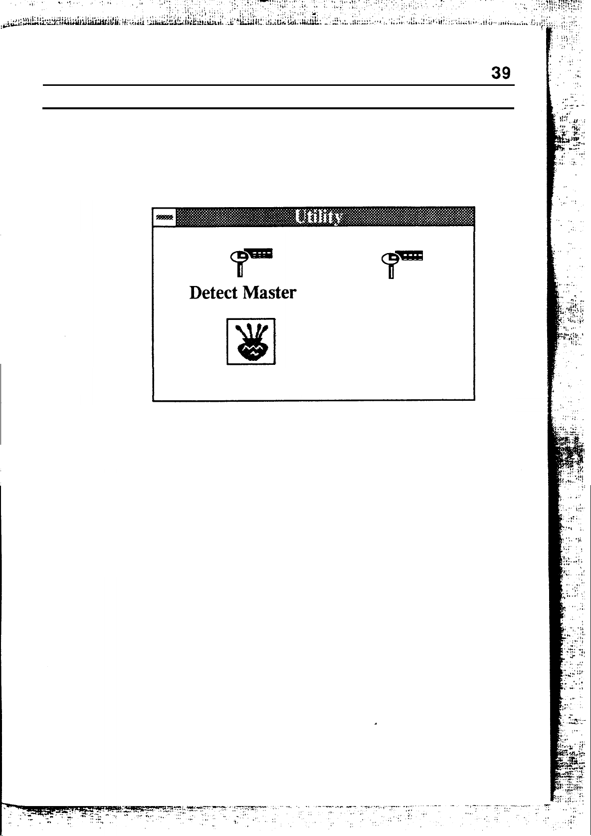
Utility Window
The Utility window has three icons that allow you to set
following options.
.
Detect Slave
Color Set
Detect Master: and Detect Slave:
If Drive C: or Drive D: is an IDE drive, the
automatically detects the hard disk drive parameters, which
appear in this screen, allowing you to configure the drive.
Color Set
This utility
lets you set the WinBIOS Setup screen colors.
BIOS
Page 44
40 Chapter 4
Security Window
The Security window has two icons with security functions.
Password
Password
1.
2.
3.
4.
Select this icon and the Password keyboard appears.
Enter a
pen stylus, or typing your keyboard. The password does
not appear on the screen when typed.
If you do not type any characters, and just press the
“Enter” key twice, the password is disabled.
The BIOS prompts you to re-enter the password to
confirm.
Make sure “Password Checking” in the Advanced Setup
is configured for “Always” or “Setup.” See the section
above on “Advanced Setup.“
l~6
character password using either a mouse or
Page 45

AMI
WinBIOS
Setup
Anti-Virus
Double-click this icon and a list box appears, allowing you to
enable or disable the Virus Protection feature. When Enabled
the BIOS issues a warning when any program or virus sends a
Disk Format command or tries to write to the boot sector of a
hard disk drive.
Formatting the Hard Disk Drive
You should not enable anti-virus protection when formatting a
hard disk drive.
41
The DOS hard disk Format utility does not use INT
function
hard disk using the INT
virus warning message is not displayed during DOS hard disk
drive formatting.
If the anti-virus feature is enabled, a virus warning message is
displayed when you attempt to format the hard disk drive.
If you select Continue, formatting proceeds as normal. If you do
not want to continue formatting, you may have to press
several times (depending on how many retries are performed
by the upper-level software% DOS, for example, does at least
five retries before the Format utility is actually aborted.
AH=05h
to format the hard disk. It only verifies the
13h
Verify function
(AH=04h).
13h
The
N
Page 46
42
Chapter
4
Default
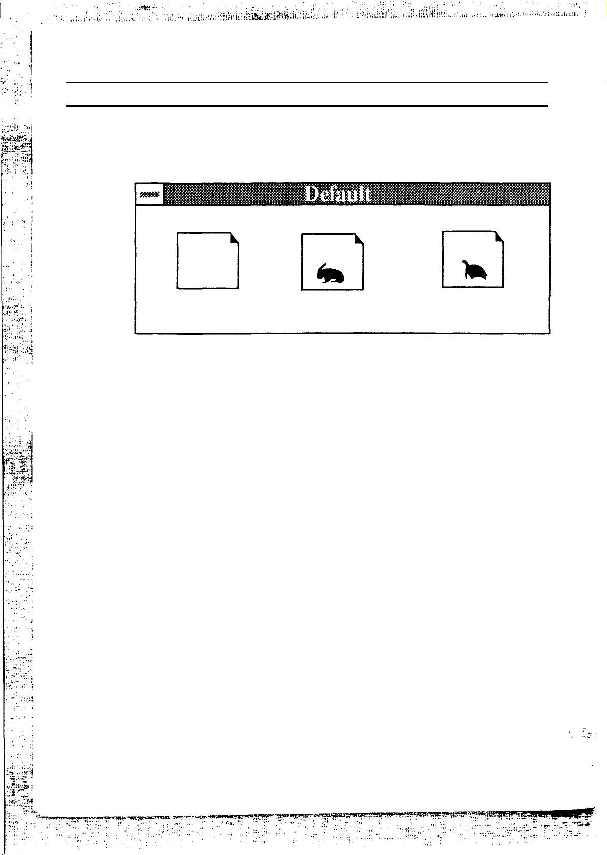
The Default window has three BIOS default settings.
Original
Original
Select
present in the WinBIOS Setup when you first began this
this icon to return to the system configuration values
Window
Optimal
Fail-safe
WinBIOS Setup session.
Optimal
Select this icon for settings that provide the best performance
characteristics. If CMOS RAM is corrupted, the Optimal
settings are loaded automatically.
Fail-Safe
Select this icon for the most stable settings but do not provide
optimal system performance. Use this option as a diagnostic
aid if the system is behaving erratically.
Page 47

AMI
WinBIOS Setup
Exiting WinBlOS Setup
43
To exit the
1.
Press <ESC> with the keyboard until the Exit Setup
window appears, or use the mouse to click the exit box in
the screen’s upper left comer.
2.
When the Exit Setup window appears, choose one of the
following:
“Save Changes and Exit” saves your changes and reboots
the system.
“Do not save changes and exit” ignores your changes and
exits the program
“Continue” continues with the CMOS Setup.
WinBIOS
Setup program:
 Loading...