

SHURflo Water wizard 150 Instructions Manual
TM
WATER WIZARD
HAND PUMP MODEL 150
FEATURES
Delivers Water in both stroking directions.
••••
Retrofits into most existing hand pump installations.
••••
"Twist of the Wrist" Hands-Free operation with city water.
••••
Easy winterizing and sanitizing.
••••
FDA materials.
••••
All corrosion resistant materials.
••••
Parts supplied with aftermarket pump, model #150-001-00:
••••
(1) Swivel Barb 1/2" Hose Fitting # 8-161-00
(2) Hose Clamps
(4)
(1) Sealing Cap
READ ALL INSTRUCTIONS BEFORE STARTING
READ ALL INSTRUCTIONS BEFORE STARTING THE INSTALLATION
READ ALL INSTRUCTIONS BEFORE STARTING READ ALL INSTRUCTIONS BEFORE STARTING
CAUTION:
CAUTION:
#
6 Screws
THE INSTALLATION
THE INSTALLATION THE INSTALLATION
DO NOT freeze
with water in pump. Refer to page 2 f or
Winterizing inst ruct ions.
DO NOT
snap the square trim cover to the pump unt il the
unit is correctly located and screwed into position.
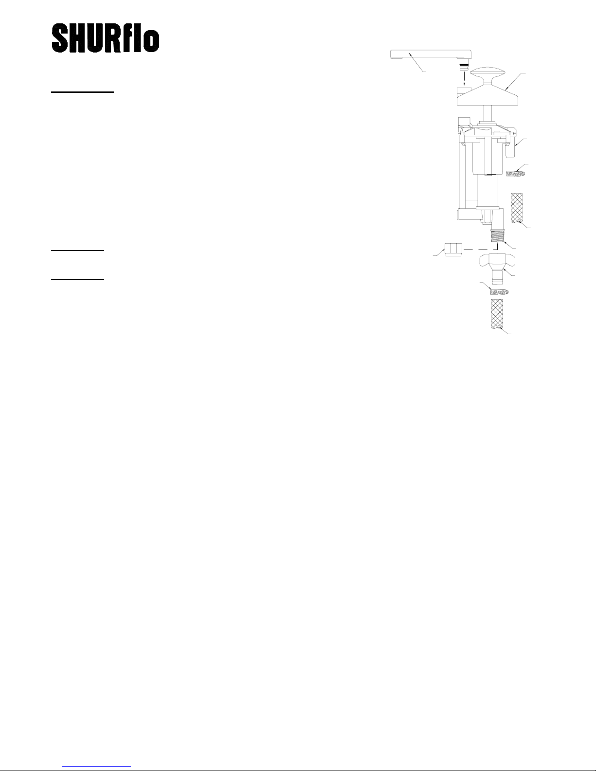
SPOUT
TRIM COVER
3/8"[10mm]
INLET
FITTING
*
POTABLE
WATER
TANK
1/2" - 14
SEALING
CAP
*
*
THREAD
*
NOTE:
The procedure outlined below is for new installations. To install
the spout there
behind the unit (back wall) and there
interference to the lef t side of the unit
To remove trim plate, slip screwdriver into slot on plate, and
gently
pry up on both sides.
be 2½"
must
[6.35 cm]
clearance from the templat e centerline to any interference
be 4¾"
must
(see template)
[12.06 cm]
. If the W izard is to replace an existing hand
REGULATED
CITY WATER
from the centerline to any
pump, modifications to the existing hole may be required. Use the template to det ermine if the
trim cover will cover an existing hole after modifications. In most installations there are
limitations on space. Use of a hole saw allows the easiest and most precise method to m ake the
cut out.
Determine the position and check under the counter for adequate space to mount the pump. Make
1.
certain there is sufficient clearance to rotate the spout when installing . Also, if mounted in a flip galley,
check for proper clearance in bot h positions f or the pump and tubing. Mark layout lines in-line with the
center of the drain, and 2¼"
[5.72 cm]
from the outer edge of the sink rim. T he ¼"
[6.35 mm]
clearance
will allow cleaning between the trim cover and the sink rim.
Cut the template
2.
(Page: 3)
lines and hold in place with tape. Mark (pilot drill) the position of the four 1¾"
Use a 1¾"
3.
[4.44 cm]
hole saw to cut the four holes. Trim out t he remaining material to att ain t he cut-out
shown on the template
shown.
Place the pump in the cut-out and sq uare it to the sink. Squaring up the pump is easier if the trim
4.
cover is placed in position,
remove the pump before drilling small pilot holes for
out around the "edge of t rim cover." Position the template over the layout
holes.
.
(bold line)
The trim cover may not cover the hole if enlarged past t he size
but DO NOT snap it in place!
[4.44 cm]
Mark the four mounting holes and
#
6 hardware*. If using a power screwdriver,
pilot holes may not be necessary. If installing into an existing hole, simply install the supplied
screws into the existing holes.
On the water line between the tank and pump a water strainer is recom mend. To protect the pump
5.
a 50 mesh screen
*
supplied with after market pump #150-001-00
(or finer)
is necessary, such as the SHURflo Potable Water Strainer #170-061-XX
911-439 Rev. G 5/99 Page: 1 of 4

Connect the tubing from the potable water tank t o t he inlet fitting. The r egulated city water line
6.
connected with the swivel barb fitting* to the threaded port at the bottom of the pump.
OVER-TIGHTEN! HAND TIGHTEN O NLY!
feature is not being used, install the threaded seal cap*.
Secure the tubing with hose clamps*. If the city water
DO NOT OVER-TIGHTEN! HAND
TIGHTEN ONLY!
Install the pump back into the hole and fasten in place.
7.
DO NOT
over tighten the screws. Doing so
can distort the plastic bosses creating difficulty when snapping the trim plate in place.
(if used)
is
DO NOT
8.
Perform a visual inspect ion of the inst allation before snapping the t rim plate into posit ion.
To
install the spout, align marks on spout and trim plate. Press spout into the hole, and turn to the
forward position. Test the pump for proper operation and check tubing for leaks. Remove and
properly discard spout label.
*
supplied with after market pump #150-001-00
OPERATION
Water from Tank: Fill water tank. Pump the piston up and down. Make sure all connections are tight.
A.
City Water: ON: Turn handle counter clockwise 1/4 turn. OFF: Return handle clockwise 1/4 turn.
B.
SANITIZING
Mix into solution, ½ ounce of common household bleach for every gallon of potable water tank capacity
[liter ≈ 1 ml] and then fill the tank completely. Operate the pump until the chlorine odor is detected.
Allow the solution to have a 4-hour contact time, and then drain the holding tank. Refill t he tank and
operate pump until the line is flushed clear of solution.
WINTERIZING
CAUTION:
DO NOT
use propylene glycol based anti-freeze fluids.
Never
To winterize the pump, simply drain t he holding tank. Operate the pump unt il all water is flushed from
the lines. Remove the city water inlet fitting or threaded cap and collect the water that drains out.
Operate the pump several strokes then reinstall the city water fitting or cap.
thawed before using!
allow water freeze in pump.
Make sure pump is
LIMITED WARRANTY
Water Wizard
SHURflo warrants the
Water Wizard
hand pump to be free from material and work manship defects (under norm al
use and service) for a period of one (1) year from the date of manufac ture, or one (1) year of use, with proof of
purchase. In no case will the terms of this limited warranty extend beyond two years from the date of manufacture.
Warranty claims m ay be resolved by the nearest authorized dealer service center, or by a SHURflo service center.
All returns are to be shipped with charges pre-paid. Pac kage all returns carefully. SHURflo will not be responsible
for freight damage incurred during shipping.
For complete warranty details refer to SHURflo Service Bulletin #1041.
!
ISO Certified Facility
SHURflo reserves the right to update specifications, prices, or make substitutions.
SHURflo
12650 Westminster Ave.
Santa Ana, CA 92706-2100
(800) 854-3218 (714) 554-7709
FAX (714) 554-4721
Shipping/UPS:
Garden Grove, CA 92843
!!!!
12650 Westminster
Ave.
SHURflo East
52748 Park Six Court
Elkhart, IN 46514-5427
((800) 762-8094 (219) 262-0478
FAX (219) 264-2169
http://www.shurflo.com
© 1999
SHURflo Ltd.
Unit 5 Sterling Park
Gatwick Road, Crawley
West Sussex, RH10 2QT
United Kingdom
+44 1293 424000
FAX +44 1293 421880
911-439 Rev. G 5/99 Page: 2 of 4
 Loading...