

BLASTER
SERIES WASH-
DOWN PUMP
SHURflo's Blaster series pumps are designed to handle the harsh
marine environment. Blaster motors have
precision ball bearings
supporting the armature. Each motor is protected by an integral
thermal
breaker
, and are all
U/L Marine listed
. Blaster pressure
switches are
sealed
and the motors are finished with a baked-on
polyurethane
coating
to inhibit corrosion. The "Pro-Blaster" motor is sealed in an
exceptionally tough
epoxy powder coated finish
, allowing it to be in
environments where "splashed water" may be present. Blaster series
pumps are enclosed to prevent incidental moisture from entering;
however, they are not
submersible
units.
The Blaster delivers water on demand. W ith the spray nozzle off
(output
side closed)
the pump will turn off . As the nozzle is opened the pressure
within the hose
(output side)
drops. Once the pressure drops below a
predetermined point the pumps pressure switch closes and the pump
operates. Wit h the nozzle set at a fine mist the pump will cycle, as it is
able to pressurize the hose faster t han water being r eleased. If the spray
nozzle is held wide open the pump will operate continually. The pump
may momentarily operate even after the nozzle is closed, as it
pressurizes the hose. Once the pressure setting is reached the switch
opens and the pump stops.
DUTY CYCLE
Wash-down pumps are rated f or int ermittent duty (only), as they operate at higher than averag e pr essur es. Operating a pump continuously for more
than twenty (20) minutes, within an hour period, is not recommended. Actual dut y cycle is determined by amp draw, tem per at ure, and rate of cycling.
NOTE:
Rapid cycling should be minimized to ensure long life. Rapid cycling is defined as
ON/OFF
within two seconds.
911-444 Rev. E 10/98
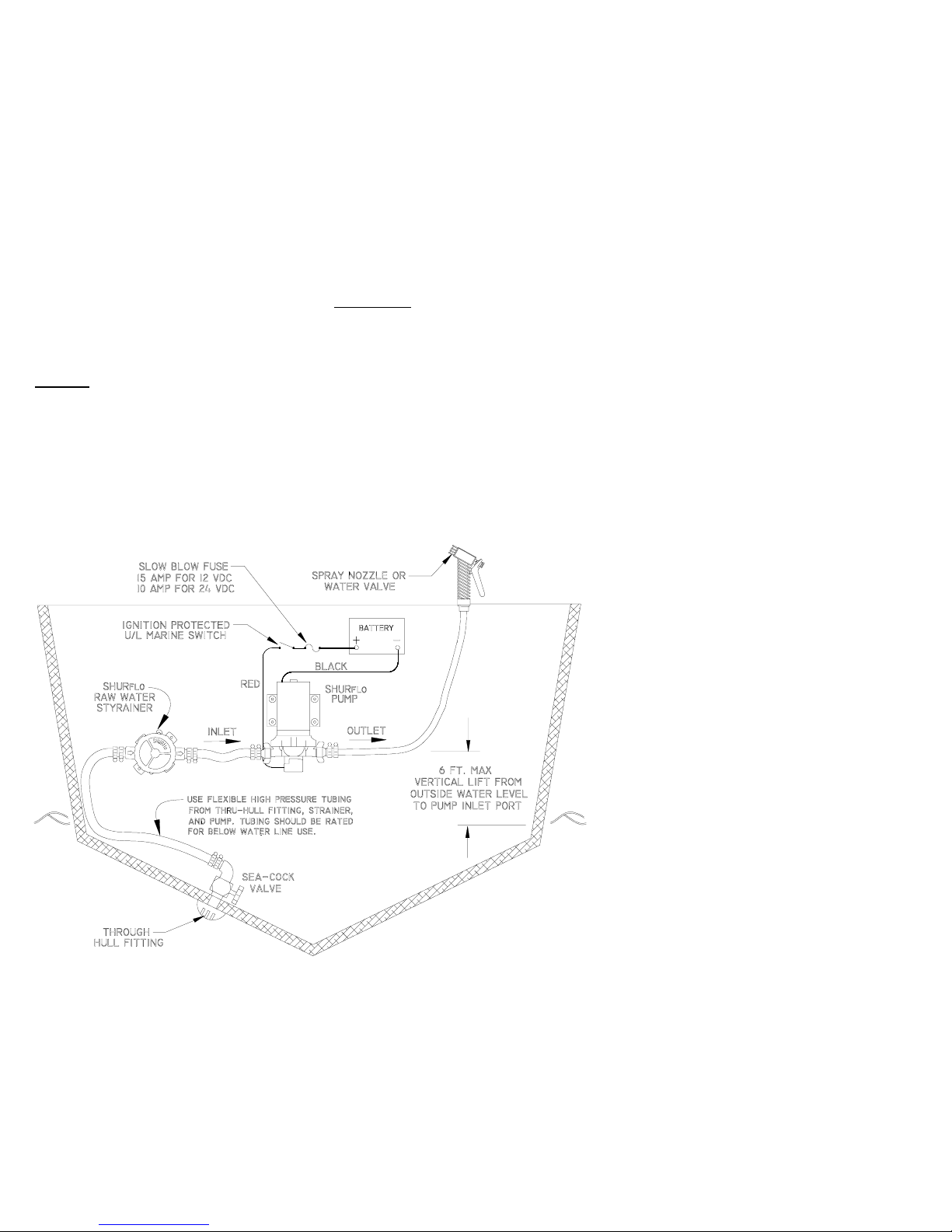
MOUNTING
•
Consider a dry location that allows easy access
if maintenance is required. The pump should
not be located in an area of less than one cubic
foot unless adequate ventilation is provided.
Excessive heat may trigger the integral thermal
breaker and interrupt operation. When the
temperature drops the breaker will automatically
reset and start operation.
•
Mount higher than the outside water (sea)
level. The pump is capable of a 6 ft. [2
M
]
vertical prime above the outside water level.
The pump can be mounted in any position. If
mounting the pump vertically, the pump head
should be in the down position.
CAUTION:
Do not drive screws through the
vessel's hull.
•
Use
#
8 stainless steel hardware to fasten the
pump. Choose a solid surface
(bulkhead or
stringer)
that will not amplify pump sound. The
mounting feet are int ended to isolate the pump
from the mounting surface; over-tightening,
flattening, or oversized screws will reduce the
mounting pads ability to isolate vibration/noise.
ELECTRICAL
•
The pump should be on a dedicated
(individual)
circuit protected on the positive (+
red) lead with the proper size "slow blow"
fuse. For all 12
VDC
pumps use a 15 amp
fuse, on 24
VDC
pumps use a 10 amp fuse.
The total current draw on the circuit must not
exceed 15 amps.
INSTALLATION AND OPERATION MANUAL
•
An ignition protected switch (U/L approved
marine duty) rated at or above 15 amps is
recommended, and must interrupt current flow
on the positive (+ red) lead.
CAUTION:
Use of "open" type switches (not ignition
protected) may cause an explosion of fuel vapors.
•
Wire size
(gauge/Mm2)
is based on the distance
from the power source to the pump. The
min imu m recommended wire size is
#
14 gauge
[2.5Mm
2
].
For lengths of 20-50 ft
.
[6-15M]
use #12
gauge
[4Mm2].
•
The pump must be grounded to a "known
ground" (battery). The ground wire must be
the same size as the positive wire.
PLUMBING
•
SHURflo swivel barb fittings provide easy
removal if maintenance or access is required.
The fittings are designed with a "taper-seal",
creating a water tight connection when hand-
tightened. Always secure barb tubing
connections with properly sized stainless steel
clamps to prevent leaks. Retail pump kits
include two ¾" swivel barb fittings
(straight/
elbow)
and an adapter to connect a standard
garden hose to the pump outlet fitting.
•
Avoid any sharp radius in tubing that may kink
over time. Route tubing away from any heat
(exhaust manifolds etc.)
and fasten securely.
•
Inlet tubing
(½"I.D. min.)
from the sea-cock
valve to the pump should be rated for
vacuum. If rigid pipe is utilized, SHURflo
recommends that the pump inlet port be
plumbed with 1 ft. [.3
M
] of flexible tubing.
Standard garden hose is not suitable as inlet
tubing as it may collapse under vacuum,
reducing water flow.
•
The pump outlet port should not be connected
to rigid
(plastic)
pipe. Normal oscillation of the
pump may transmit through rigid plumbing
causing noise and possibly loosen or crack
components. A 1ft.
[.3M]
length of flexible high
pressure tubing is suggested.
 Loading...