

Page 1
STEREO WIRELESS
PERSONAL MONITORING SYSTEM
®
PSM 300
USER GUIDE
Le Guide de l’Utilisateur
Manuale d’uso
Bedienungsanleitung
Guia del Usuario
Gebruikershandleiding
Guida dell’Utente
Руководство пользователя
© 2014 Shure Incorporated
27A23049 (rev. 1)
Printed in China
Page 2
IMPORTANT SAFETY INSTRUCTIONS
1. READ these instructions.
2. KEEP these instructions.
3. HEED all warnings.
4. FOLLOW all instructions.
5. DO NOT use this apparatus near water.
6. CLEAN ONLY with dry cloth.
7. DO NOT block any ventilation openings. Allow sufficient distances for adequate
ventilation and install in accordance with the manufacturer’s instructions.
8. DO NOT install near any heat sources such as open flames, radiators,
heat registers, stoves, or other apparatus (including amplifiers) that
produce heat. Do not place any open flame sources on the product.
9. DO NOT defeat the safety purpose of the polarized or groundingtype plug.
A polarized plug has two blades with one wider than the other. A grounding
type plug has two blades and a third grounding prong. The wider blade or the
third prong are provided for your safety. If the provided plug does not fit into
your outlet, consult an electrician for replacement of the obsolete outlet.
10. PROTECT the power cord from being walked on or
pinched, particularly at plugs, convenience receptacles,
and the point where they exit from the apparatus.
11. ONLY USE attachments/accessories specified by the manufacturer.
12. USE only with a cart, stand, tripod, bracket, or table specified by the
manufacturer, or sold with the apparatus. When a cart is used, use caution
when moving the cart/apparatus combination to avoid injury from tip-over.
13. UNPLUG this apparatus during lightning storms or
when unused for long periods of time.
14. REFER all servicing to qualified service personnel. Servicing is required
when the apparatus has been damaged in any way, such as power
supply cord or plug is damaged, liquid has been spilled or objects
have fallen into the apparatus, the apparatus has been exposed to
rain or moisture, does not operate normally, or has been dropped.
15. DO NOT expose the apparatus to dripping and splashing. DO NOT
put objects filled with liquids, such as vases, on the apparatus.
16. The MAINS plug or an appliance coupler shall remain readily operable.
17. The airborne noise of the Apparatus does not exceed 70dB (A).
18. Apparatus with CLASS I construction shall be connected to a
MAINS socket outlet with a protective earthing connection.
19. To reduce the risk of fire or electric shock, do not
expose this apparatus to rain or moisture.
20. Do not attempt to modify this product. Doing so could
result in personal injury and/or product failure.
21. Operate this product within its specified operating temperature range.
WARNING: This product contains a chemical known to the State of California to
cause cancer and birth defects or other reproductive harm.
SAFETY PRECAUTIONS
The possible results of incorrect use are marked by one of the two symbols—
"WARNING" and "CAUTION"—depending on the imminence of the danger and the
severity of the damage.
WARNING: Ignoring these warnings may cause severe injury or death as
a result of incorrect operation.
CAUTION: Ignoring these cautions may cause moderate injury or
property damage as a result of incorrect operation.
CAUTION
• Never disassemble or modify the device, as failures may result.
• Do not subject to extreme force and do not pull on the cable or failures may
result.
• Keep the product dry and avoid exposure to extreme temperatures and humidity.
WARNING
• If water or other foreign objects enter the inside of the device, fire or electric shock
may result.
• Do not attempt to modify this product. Doing so could result in personal injury and/
or product failure.
This device is able to produce sound volume higher than 85 dB SPL. Please
check your maximum allowed continuous noise exposure level based on your
national employment protection requirements.
WARNING
LISTENING TO AUDIO AT EXCESSIVE VOLUMES CAN CAUSE PERMANENT
HEARING DAMAGE. USE AS LOW A VOLUME AS POSSIBLE. Over exposure
to excessive sound levels can damage your ears resulting in permanent noiseinduced hearing loss (NIHL). Please use the following guidelines established by the
Occupational Safety Health Administration (OSHA) on maximum time exposure to
sound pressure levels before hearing damage occurs.
90 dB SPL
at 8 hours
110 dB SPL
at ½ hour
95 dB SPL
at 4 hours
115 dB SPL
at 15 minutes
100 dB SPL
at 2 hours
105 dB SPL
at 1 hour
120 dB SPL
Avoid or damage may occur
Important Product Information
LICENSING INFORMATION
Licensing: A ministerial license to operate this equipment may be required in certain
areas. Consult your national authority for possible requirements. Changes or
modifications not expressly approved by Shure Incorporated could void your authority
to operate the equipment. Licensing of Shure wireless microphone equipment is
the user’s responsibility, and licensability depends on the user’s classification and
application, and on the selected frequency. Shure strongly urges the user to contact
the appropriate telecommunications authority concerning proper licensing, and
before choosing and ordering frequencies.
Information to the user
This equipment has been tested and found to comply with the limits for a Class
B digital device, pursuant to Part 15 of the FCC Rules. These limits are designed
to provide reasonable protection against harmful interference in a residential
installation. This equipment generates uses and can radiate radio frequency energy
and, if not installed and used in accordance with the instructions, may cause
harmful interference to radio communications. However, there is no guarantee that
interference will not occur in a particular installation. If this equipment does cause
harmful interference to radio or television reception, which can be determined
by turning the equipment off and on, the user is encouraged to try to correct the
interference by one or more of the following measures:
• Reorient or relocate the receiving antenna.
• Increase the separation between the equipment and the receiver.
• Connect the equipment to an outlet on a circuit different from that to which the
receiver is connected.
• Consult the dealer or an experienced radio/TV technician for help.
This device complies with Industry Canada licence-exempt RSS standard(s).
Operation of this device is subject to the following two conditions: (1) this device may
not cause interference, and (2) this device must accept any interference, including
interference that may cause undesired operation of the device.
Le présent appareil est conforme aux CNR d'Industrie Canada applicables aux
appareils radio exempts de licence. L'exploitation est autorisée aux deux conditions
suivantes : (1) l'appareil ne doit pas produire de brouillage, et (2) l'utilisateur de
l'appareil doit accepter tout brouillage radioélectrique subi, même si le brouillage est
susceptible d'en compromettre le fonctionnement.
Industry Canada ICES-003 Compliance Label:
CAN ICES-3 (B)/NMB-3(B)
Note: EMC conformance testing is based on the use of supplied and
recommended cable types. The use of other cable types may degrade EMC
performance.
Changes or modifications not expressly approved by the manufacturer could
void the user’s authority to operate the equipment.
2
Page 3
PSM®300
Vocal Mix
(Channel 2)
CH 1 CH 2
CH 1 CH 2
P3T
Mixer Outputs
MONO/STEREO-MX LINE/AUX LEFT/CH.1 IN RIGHT/CH.2 INL - LOOP OUT - R ANTENNAPOWER
Personal MixMode settings
Personal MixMode settings
Instruments
Vocals
Instruments
Vocals
Stage signals
to mixer inputs
Instrument mix (channel 1)
Vocal mix (channel 2)
Mixer Outputs
Drums
Vocals
Instruments
power
group channel
sync
PSM300 Transmitter P3T
(1-F)
(1-9)
input
P3T Transmitter
P3R or P3RA Bodypack Receiver
¼ Wave Antenna
SE112 or SE215 Earphones
Rackmount Hardware Kit
Carrying Bag
PS23 Power Supply
(2) AA Batteries*
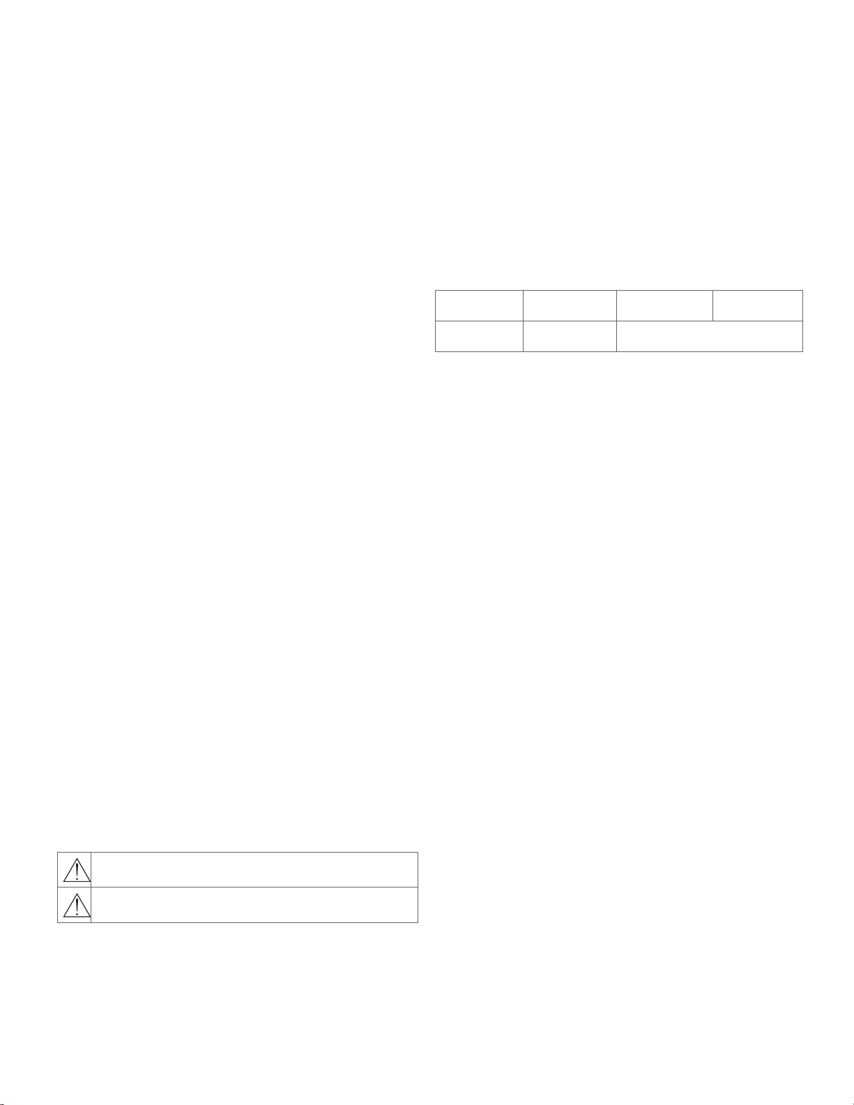
The PSM300 Personal Monitor System delivers wireless stereo monitoring
for improved clarity and reduced feedback over traditional stage wedges.
Performers can create their own custom mixes by adjusting the stereo
blend and overall volume level at the bodypack, resulting in lower volume
on stage and enhanced audio detail. Easy to set up and operate, PSM300
features one-touch frequency syncing and solid wireless RF stability
between transmitters and receivers. With rugged, dependable hardware
and hard-working technology, Shure PSM300 Personal Monitor Systems
deliver a greatly improved monitoring experience on stage.
Features
• Send two channels of audio wirelessly to performers onstage
• Solid RF connection over a 300 foot (90 meter) range
• Create a personal mix on each bodypack with adjustable stereo
balance or MixMode® two-channel mono blend.
• Up to 90 dB signal-to-noise ratio provides clear, detailed audio at any
volume
• Systems available with Shure Sound Isolating™ earphones
• One-touch scan and IR sync quickly and easily assigns a clean
wireless channel
• No complicated menus, just simple volume and mix controls that focus
on the performance
• All-metal half-rack transmitter
• Slim, lightweight bodypack attaches easily to a belt or guitar strap
System Overview
Included Components
*Not included in Argentina
This example shows a typical setup for musical performance. See the
System Applications section for additional examples.
① Route audio signals
Send Instrument and microphone signals from the stage to a mixer
or PA system.
② Create monitor mixes
From the mixer, create two mixes: one of just the instruments, and a
second with just the vocals. Route each of these to separate mixer
outputs and connect them to the P3T inputs.
③ Send wireless audio to the performers
Sync the bodypacks to the P3T transmitter to send the mixes to the
performers for in-ear monitoring.
④ Adjust personal mixes
Each performer uses the MixMode knob on the bodypack to control
their own mix between the instruments and vocals .
3
Page 4
power
group channel
sync
PSM300 Transmitter P3T
(1-F)
(1-9)
input
L
R
OL
OL
sync
Tx Rx
stereo/mx mono
aux
line
0dB
group
channel
tv
ௗ
MONO/STEREO-MX LINE/AUX LEFT/CH.1 IN RIGHT/CH.2 INL - LOOP OUT - R ANTENNAPOWER
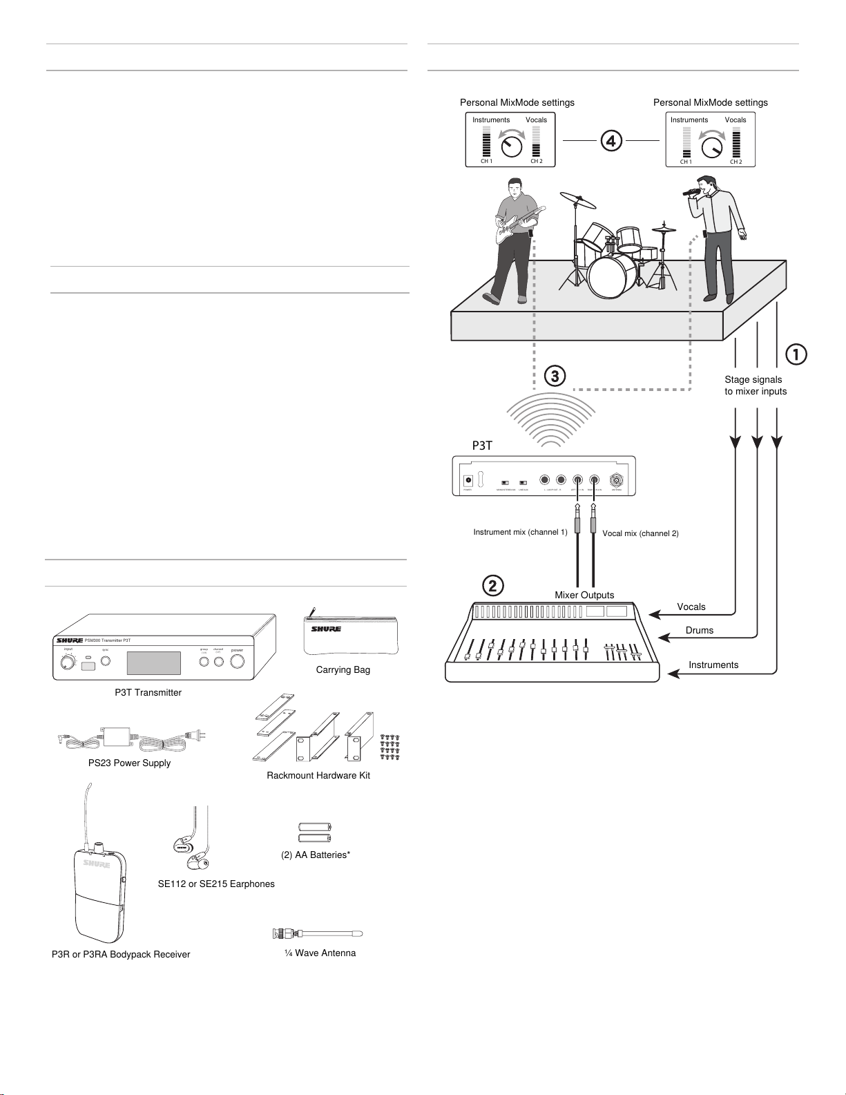
▇ Hardware
P3T Transmitter Front and Rear Panels
① ②
① Input Level Control
Adjusts the level of the incoming audio signal
② IR Sync Window
Sends and receives group/channel data to sync receivers with
the transmitter
③ Sync Button
Press to synchronize the transmitter and receiver to the same
group and channel
Note: Sync data is sent through the IR sync window
④ LCD Display
Displays audio, RF, and system information
⑤ Group Button
Press to scroll through group settings
⑥ Channel Button
Press to scroll through channel settings
⑦ Power
Turns power on or off
③
④
P3T Front Panel
⑤ ⑥ ⑦
⑧
⑧ Power Input
Connect the supplied Shure PS23 external power supply
⑨ Mono/Stereo-MX Switch
StereoMX
Mono
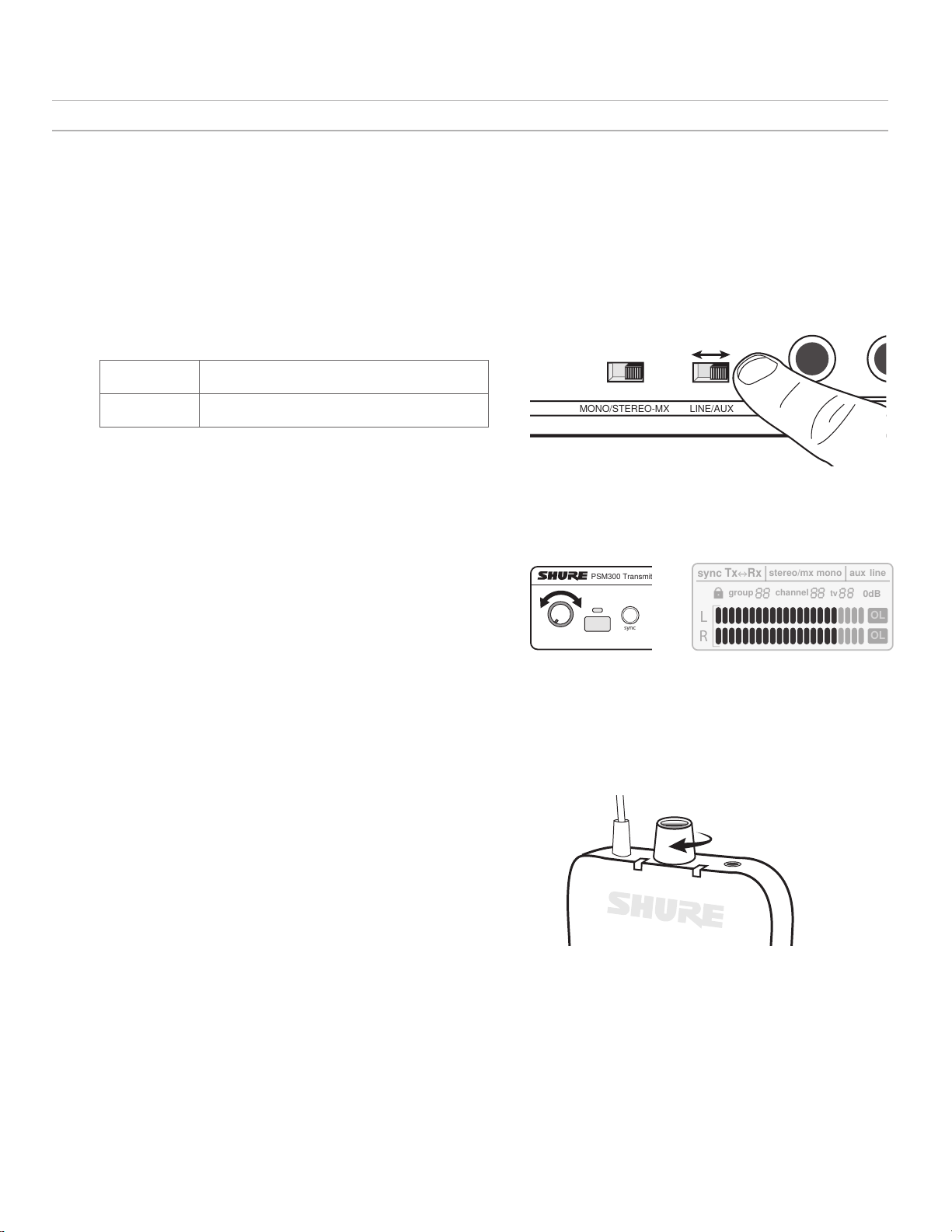
⑩ Line/Aux Switch
Adjust the input sensitivity using the following as a connection reference:
Aux (-10 dBV):
Line (+4 dBu):
⑪ Loop Outputs (¼ Inch TRS, Balanced)
Connect outputs to additional PSM systems or other audio devices
⑫ Audio Inputs (¼ Inch TRS, Balanced)
Connect to mixer outputs or other audio sources for monitoring by the
performers
⑬ BNC Antenna Connector
Connect the supplied ¼ wave antenna, directional antenna, or a Shure
P3AC antenna combiner
Sends a two-channel stereo mix to the receiver
Sends a summed audio mix to both receiver channels
Consumer audio devices, such as computers or portable
media players
Mixers or other professional audio devices
⑨
⑩
P3T Rear Panel
⑪ ⑫
⑬
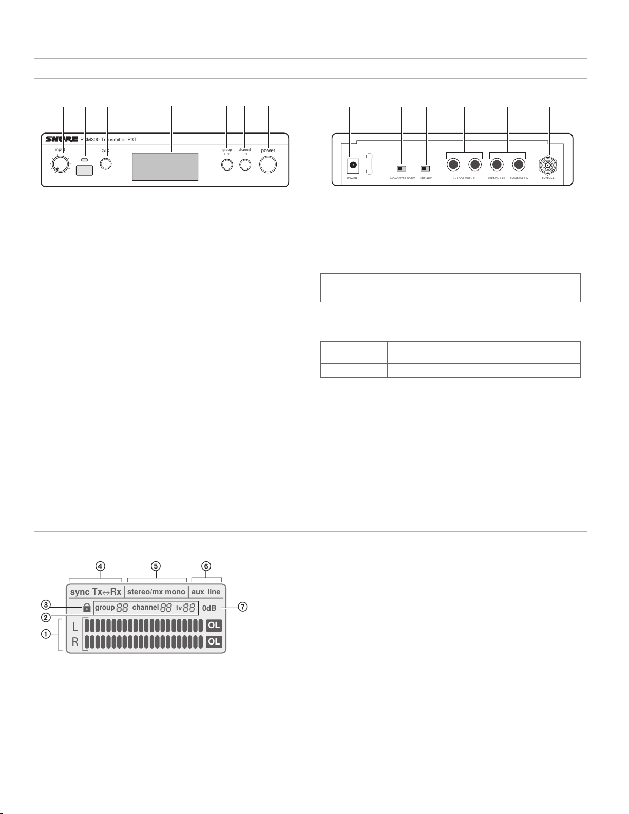
P3T Transmitter Display
① Audio Input Meter
Indicates the audio signal level
② Group / Channel / TV Setting
Displays selected group and channel settings and the
corresponding television channel
Note: the TV indicator only applies to U.S.A. channels, and remains
blank in other regions
③ Lock Status
To lock or unlock the controls, press and hold the group and channel buttons
until the lock icon appears/disappears.
④ Sync Status
Appears after a successful sync between the transmitter and receiver. The
direction of the sync is shown as Tx>Rx (transmitter sends frequency to
receiver) or Tx<Rx (receiver sends frequency to transmitter).
⑤ Stereo-MX / Mono Mix
Indicates whether the audio sent to the receiver is a single or two-channel mix
(corresponds to the Stereo-MX/Mono switch on the rear panel).
⑥ Aux / Line Mode
Indicates the input sensitivity setting (corresponds to the Aux/Line switch on
the rear panel)
⑦ 0 dB Indicator
Turns on when input signal reaches 0 dB. Refer to the section on adjusting gain
and listening volume for information on how to use this icon.
4
Page 5
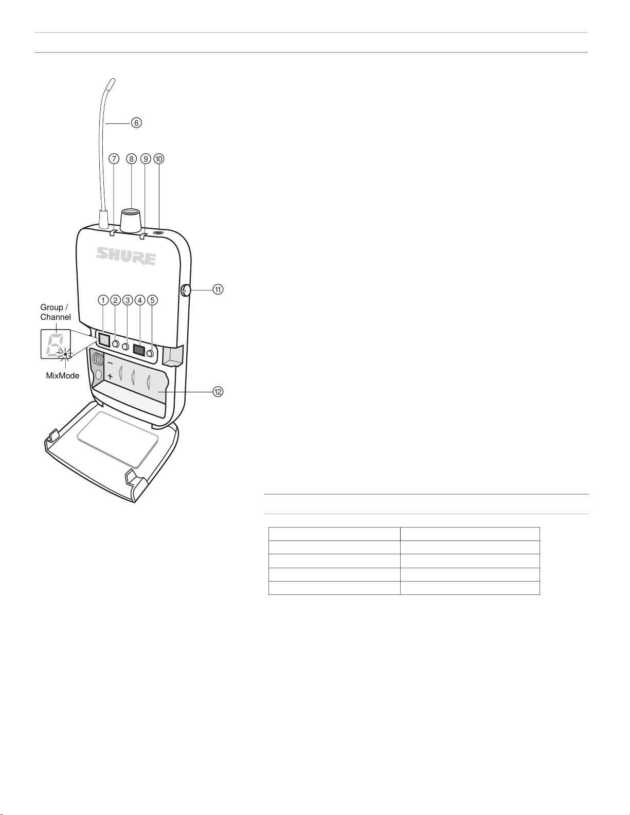
P3R Wireless Receiver
௦ ௧ ௨
௩
௪
MixMode
Group /
Channel
① Display
Shows group, channel, and MixMode settings
② Group Button
• Press to display group
• Press and hold to edit the group, then press to scroll when display flashes
③ Channel Button
• Press to display channel
• Press and hold to edit the channel, then press to scroll when display flashes
④ IR Sync Window
Sends and receives sync data between the receiver and transmitter
⑤ Scan Button
• Press and hold to perform a group scan
• Press to perform a channel scan
Note: A channel scan selects the best channel in the current group. A group scan finds the group
with the most open channels and selects the first available channel in that group.
⑥ Antenna
⑦ Power LED Indicator
Indicates when receiver is on, remaining battery life, and when power-save mode is
active. See battery life table for more information.
⑧ Power Switch / Volume Control Knob
Turns the receiver on/off and adjusts master headphone volume level
P3R
P3RA Receiver
For more demanding applications, Shure offers
the P3RA receiver, which features all-metal
construction and advanced menu navigation
in addition to the features included on the P3R
receiver. For more information, please visit
www.shure.com.
⑨ RF LED Indicator (blue)
Illuminates when tuned to an active transmitter group and channel
⑩ Headphone Output
Connects to earphones or headphones
⑪ MixMode Control Knob
• When operating in MixMode, this knob blends channels 1 and 2 into a single mix
• When operating in stereo mode, this knob adjusts the left/right balance
⑫ Battery Compartment
Holds 2 x AA batteries
Battery Life
LED Behavior Remaining Runtime (Hours)
Green 5-7
Amber 1-3
Red (solid) 0.5-1
Red (flashing) 0
Battery life was measured using Energizer™ alkaline batteries, under the
following conditions:
• Transmitter sensitivity: Line (+4dBu)
• Audio output from receiver: 100 dB through Shure SE112 earphones
Power-save mode: When there are no earphones plugged in, the receiver enters
power-save mode to preserve battery life. The LED slowly fades on/off in this
mode and continues to display the color that represents the remaining battery life.
5
Page 6
P3T
power
group channel
sync
PSM300 Transmitter P3T
(1-F)
(1-9)
input
Mixer Outputs (Auxiliary/Monitor)
power
group channel
sync
PSM300 Transmitter P3T
(1-F)
(1-9)
input
P3T
Mixer Outputs (Auxiliary/Monitor)
▇ Applications
Refer to the following PSM300 system scenarios prior to installation. Understanding the configuration options before setting up helps to identify signal
routing requirements and plan for future expansion. Specific information on how to set up the PSM300 system and create mixes for monitoring can be
found in the "System Setup and Configuration" and "Operation" sections of this user guide.
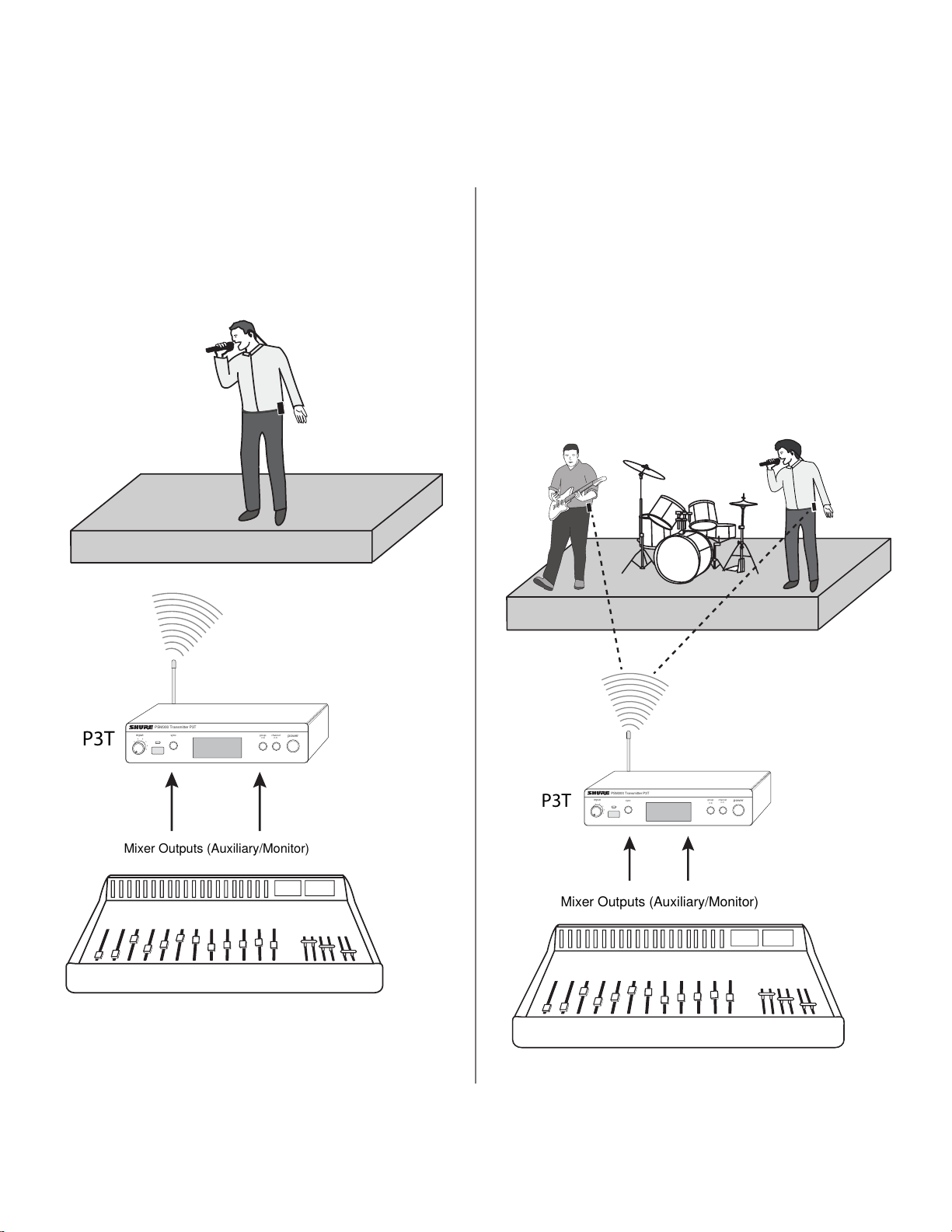
Single System for an Individual Performer
This configuration provides in-ear monitoring in a solo performance,
or in a group performance in which only one person requires wireless
monitoring. This system can be expanded for multiple performers
by using additional P3R bodypack receivers tuned to the same
transmitter.
Single Transmitter with Multiple Receivers
Multiple performers can monitor audio from the same transmitter and
still adjust the signal at their bodypack to personalize the mix. Simply
tune each bodypack to the same frequency as the transmitter and use
the MixMode knob to adjust the mix.
MixMode or Stereo Operation:
Each performer has the option of setting their bodypack to MixMode or
Stereo when the transmitter is set to Stereo-MX. When the bodypack
is powered on, it is set to stereo by default. To operate in MixMode,
hold the GROUP button when turning the power on. For information on
these modes, see "MixMode and Stereo Monitoring".
6
Page 7

Multiple Transmitters with Separate Mixes
P3T
P3T
power
group channel
sync
PSM300 Transmitter P3T
(1-F)
(1-9)
input
power
group channel
sync
PSM300 Transmitter P3T
(1-F)
(1-9)
input
Mix 1
Mix 2
P3T
MONO/STEREO-MX LINE/AUX LEFT/CH.1 IN RIGHT/CH.2 INL - LOOP OUT - R ANTENNAPOWER
Stage Monitor Loudspeaker
Amplifier
Transmitter LOOP Outputs
Mixer Auxiliary/Monitor Outputs
When several performers in a group have different monitoring
requirements, multiple PSM300 systems may be used
simultaneously to send different mixes through each transmitter.
This setup requires a mixer with two monitor/auxiliary outputs for
each transmitter.
Tip: To simplify setup in applications that involve multiple
transmitters, Shure offers the P3AC antenna and power
distribution system, which supplies up to four PSM transmitters
with power and RF from a single source.
Signal Routing to External Devices
(Combination Systems)
The LOOP outputs pass audio to an external device, such as other
personal monitoring systems, recording devices, or stage monitors. The
signal at the LOOP outputs is identical to the signal coming from the
mixer, and is not affected by the transmitter volume or input sensitivity
(line/aux) settings. This makes the LOOP outputs particularly useful
when using a mixer that has one or two monitor/auxiliary sends.
Using the PSM300 simultaneously with Loudspeakers:
A combination monitoring system can be used, where some of the
performers are using the PSM300 wireless system and others are
listening through loudspeakers on stage.
Note: If using passive stage monitors, the P3T outputs must be
connected to an amplifier. Active (amplified) speakers can be
connected directly to the P3T outputs.
Using the PSM300 Combined with Other Wireless
Monitoring Systems
In a scenario where two performers have their own wireless monitoring
systems (one Shure PSM300 system and one third-party system, for
example), the PSM300 can pass the signal from the mixer on to the
second monitoring system.
7
Page 8
ௗ
MONO/STEREO-MX LINE/AUX
LEFT/CH.1 IN RIGHT/CH.2 INL - LOOP OUT - R ANTENNA
POWER
PS23
LEFT/CH.1 IN RIGHT/CH.2 INL - LOOP OUT - R ANTENNA
power
group channel
sync
PSM300 Transmitter P3T
(1-F)
(1-9)
input
Power = Off
Group
Channel
Scan
▇ System Setup and Configuration
power
group
(A-Y)
channel
(0-9)
sync
PSM300 Transmitter P3T
power
group
(A-Y)
channel
(0-9)
sync
PSM300 Transmitter P3T
power
group
(A-Y)
channel
(0-9)
sync
PSM300 Transmitter P3T
power
group
(A-Y)
channel
(0-9)
sync
PSM300 Transmitter P3T
power
group
(A-Y)
channel
(0-9)
sync
PSM300 Transmitter P3T
power
group
(A-Y)
channel
(0-9)
sync
PSM300 Transmitter P3T
Single unit
Dual-mounting two units
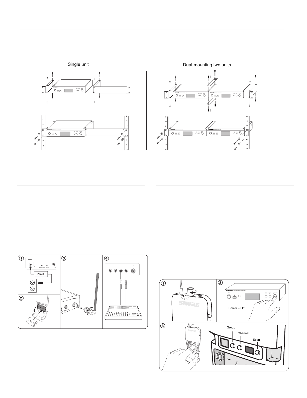
Rack Mounting
The P3T Transmitter can be mounted in a standard 19-inch rack. Up to two units can be mounted in a single rack space. If using multiple P3T
transmitters, the Shure PA411 Antenna Combiner system can be used to consolidate and distribute all RF and power for up to four transmitters.
Note: Always use both straddle bars when mounting two units.
Power, Audio, and RF Connections
1. Use the power adapter to connect the P3T to an AC power source.
2. Install 2 AA batteries in the bodypack receiver.
3. Attach the antenna to the BNC antenna
connector on the P3T rear panel.
4. Connect the mixer or audio source to the P3T
audio inputs using ¼ inch balanced cables.
Important: When connecting to only one transmitter input, use the LEFT/
CH1 input. Set the transmitter to MONO to hear audio on both channels of the
receiver.
Scanning for the Best Open Channel
Follow these steps to scan the RF environment and find the best available
frequency for operation:
1. Turn on the bodypack receiver and any potential sources of
interference, including wireless systems, computers, audio
equipment, cellular phones, LED panels, and other electronic
devices that will be in use during a performance.
2. Make sure the P3T transmitter is OFF.
3. Position the receiver in the performance area and press SCAN to
survey the available channels within the current group setting.
If using several PSM300 systems or operating in a location with a high
volume of wireless devices, perform a group scan first, followed by a
channel scan:
Group Scan: Press and hold the SCAN button on the receiver.
Channel Scan: Press the SCAN button on the receiver.
8
Page 9
Creating a Wireless Connection Between Receivers and Transmitters (Sync)
power
group channel
sync
PSM300 Transmitter P3T
(1-F)
(1-9)
input
power
group
(A-Y)
channel
(0-9)
sync
PSM300 Transmitter P3T
power
group
(A-Y)
channel
(0-9)
sync
PSM300 Transmitter P3T
To pass audio from the transmitter to the receiver, both must be tuned to the same frequency. The easiest way to configure the system is to use the
automatic sync feature. This transfers group and channel settings with a press of a button. Based on your system configuration, use one of the following
processes to sync the components:
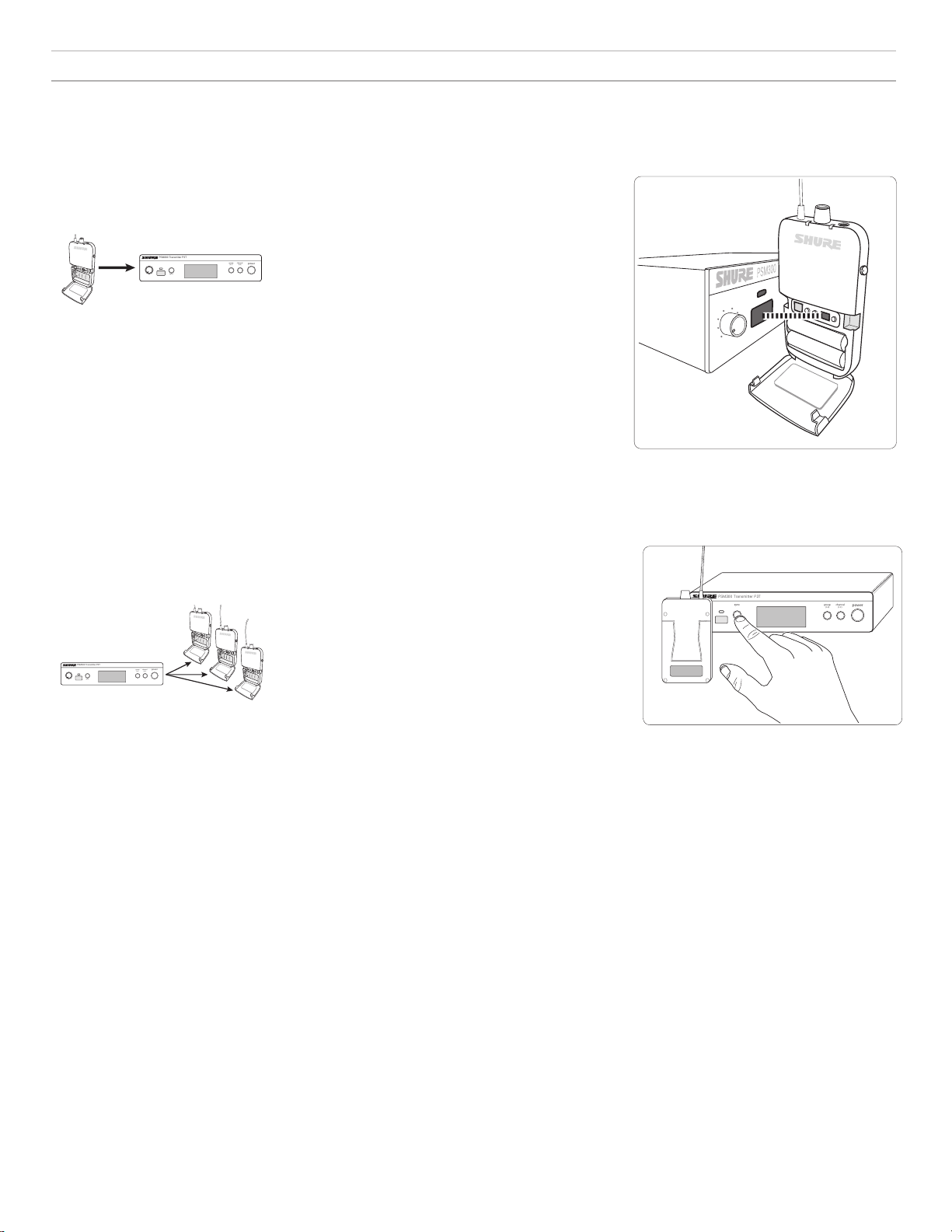
Single Transmitter and Receiver
The following sync procedure should be used with a setup that consists of a single transmitter
and receiver, unless a group/channel setting has been assigned prior to a performance.
Sync from receiver to transmitter:
1. Perform a scan on the receiver (see "Scanning for the Best Open Channel" for best practices).
2. Align the IR windows on the receiver and transmitter. The windows should be 6-11 cm apart.
3. Press the SYNC button on the transmitter while the blue RF LED on the receiver is flashing.
4. The Transmitter displays SYNC when the sync is successful. The arrow between
Rx (receiver) and Tx (transmitter) shows the direction of the sync.
Note: When the RF LED on the receiver is flashing after performing a scan, the receiver sends its
frequency setting to the transmitter. After it stops flashing, pressing SYNC sends the frequency setting from
the transmitter to the receiver.
Align the IR windows to sync the receiver
and transmitter
Single Transmitter and Multiple Receivers
The following sync procedure should be used with a setup that consists of a single transmitter
with multiple receivers, or if a specific group/channel setting has been assigned to the transmitter
prior to a performance.
Sync from transmitter to receivers:
1. Sync the first receiver to the transmitter using the sync procedure
for a single receiver. Performing a scan and using the resulting
Pressing the SYNC button transfers group/
channel data
group and channel from the receiver is recommended.
2. Set additional receivers to the transmitter frequency (one at a time) using IR sync:
• Align the IR windows on the receiver and transmitter and press SYNC.
• The receiver LED should not be flashing when pressing SYNC.
Note: Receivers can also be manually tuned to the transmitter if an IR sync is not practical.
Multiple Transmitters and Multiple Receivers
1. Set up the first transmitter and all associated receivers according to the appropriate sync procedure. Keep the
transmitter and all receivers from this first system powered on when setting up additional systems.
2. Set up each additional system using the appropriate sync process. Always leave each new system on before setting up an additional one.
Manual Selection
If frequencies have been planned ahead of time, the group and channel can be set manually without performing a scan. Refer to the frequency table at
the end of this user guide to identify frequencies for each group/channel setting.
To select group/channel settings on the receiver and transmitter:
1. Press GROUP to scroll through group settings.
2. Press CHANNEL to scroll through channel settings within the selected group.
9
Page 10
MONO/STEREO-MX LINE/AUX TRS IN
power
group
(A-Y)
channel
(0-9)
sync
PSM300 Transmitter P3T
L
R
OL
OL
sync
Tx
Rx
stereo/mx mono
aux
line
0dB
group
channel
tv
▇ Operation
Adjusting Gain and Listening Volume
For the best audio quality, start by adjusting the levels from the mixer or audio source, and then adjust levels through the PSM300 system. This
approach corresponds to the way that the audio signal flows through the system, and maximizes the signal-to-noise ratio.
Before you begin: verify all signal routing and gain settings at the mixer or source prior to adjusting any levels from the PSM300 system. If the sound is
distorted or faint when it enters the P3T transmitter, there is likely an issue elsewhere in the signal chain that needs to be resolved.
① Adjust Transmitter Levels:
Input Sensitivity
Select the setting that matches the input source:
Line (+4 dBu)
Aux (-10 dBV)
Use with mixers or other professional audio devices that
send line-level signals.
Use when connecting consumer audio devices such as
portable audio players or computers.
Note: When using consumer audio devices, the output volume of the device
should typically be adjusted as close to the maximum setting as possible without
distorting or clipping at the output of the device. This maximizes the signal-tonoise ratio.
Input Level
Adjust the level so that average levels on the audio meter reach
approximately 75% of the full range. The highest levels should
occasionally hit the 0dB indicator on the audio input meter, without
reaching the OL (overload) indicator.
Tip: If a sound check before the performance is possible, everyone
should play at the loudest anticipated volume so that attenuation is
not required during the performance.
② Adjust Receiver Volume:
After levels are established at the mixer and transmitter, use the
headphone volume control on the bodypack receiver to adjust overall
listening volume. For information on adjusting the left/right balance or
customizing the mix blend, see "MixMode and Stereo Monitoring".
10
Page 11

Creating Monitor Mixes
CH 1 CH 2
Instruments
Vocals
CH 1 CH 2
Instruments
Vocals
AUX/MON 1
AUX/MON 2
EQ
GAIN
PAN
Aux/Mon 1 Out
Aux/Mon 2 Out
STEREO-MX/MONO AUX/LINE LEFT/CH.1 IN RIGHT/CH.2 INL - LOOP OUT - R ANTENNADC INPUT
MixMode
Left (Channel 1)
Right (Channel 2)
MixMode and Stereo Monitoring
The mix that performers hear on stage is usually different than the
mix heard by the audience. In live sound applications, the engineer
creates a separate mix to send to the performer by routing the input
signals to specified mixer outputs, usually called Monitor or Auxiliary
outputs.
The following scenario demonstrates a generic signal path for
monitoring mixes, and may not reflect the routing for all mixer types.
Consult the user guide for your mixer for detailed signal routing
options.
① Mixer Channel
Each mixer channel controls audio processing and routing for
a single audio source. In this example, a vocal microphone is
plugged into the mixer channel.
② Monitor/Auxiliary Sends
Adjust the signal levels to send to the monitor/auxiliary outputs,
each of which corresponds to a separate monitoring mix. Each of
these mixes are sent to separate channels on the P3T transmitter.
Note: The channel faders on most mixers do not affect the volume of the
monitor/auxiliary sends.
③ Wireless Transmission
Each monitoring mix is transmitted on a separate channel to the
P3R receiver. The MixMode knob on the bodypack adjusts the
blend between the audio from channel 1 and channel 2.
The receiver can operate in stereo or MixMode when the transmitter is set
to STEREO-MX. In applications that involve multiple bodypack receivers tuned
to a single transmitter, some bodypacks can operate in stereo, while others
operate in MixMode.
Selecting the Mode
Stereo: The receiver is set to stereo mode by default. To switch from
MixMode to stereo, simply turn the receiver off and it will return to stereo
mode when powered back on.
MixMode: Press and hold the GROUP button on the
bodypack receiver while turning the power on. The MixMode
indicator light on the receiver display turns on to confirm the
setting. The receiver will return to stereo mode after it has
been powered off.
Stereo
Audio from channel 1 is heard on
the left earphone, while audio from
channel 2 is heard on the right
earphone. Listening in stereo mode
increases separation between the
sources on each channel, which can
improve clarity when many sources
are being monitored. The MixMode
knob on the bodypack adjusts left/
right balance when operating in stereo
mode.
MixMode
MixMode allows performers to adjust the blend between two monitoring
mixes (an instrumental mix and a vocal mix, for example). When using
MixMode:
• Each mix is heard through both the left and right earphones
• The MixMode knob adjusts the volume blend between the two monitor
mixes (channel 1 and channel 2)
• Each bodypack receiver can dial in a unique blend to meet the
monitoring needs of each performer
Adjusting mix levels
In this scenario, an instrumental mix is on channel 1 and a vocal mix is on
channel 2:
To hear more of channel one,
turn the MixMode knob to the
left.
To hear more of channel two,
turn the MixMode knob to the
right.
When to Use the Mono Setting
In some cases, only a single input on the transmitter is used (if the mixer only
features a single monitor/auxiliary output, for example). To ensure that audio
is heard on both the left and right earphones:
• Use the LEFT/CH1 input on the transmitter
• Set the transmitter to MONO
Note: When the transmitter is set to mono operation, the MixMode knob
will not affect the sound.
11
Page 12

Troubleshooting
Problem Solution
Distorted Audio • Check the volume levels at the P3T transmitter and verify that the meter is not reaching the overload indicator
No sound from receiver • Make sure the transmitter and receiver are linked to the same group and channel
Turning the MixMode knob does
not affect the sound
Low audio output at the receiver • Check headphone connection and volume level
Audio or RF drops out • Perform a scan to ensure the receiver is on a clear (available) frequency
IR sync failure Verify distance between receiver and transmitter is between 6-11 cm
• Check levels going in and out of the mixer. If audio is distorting anywhere in the signal chain, it will be distorted even if the PSM300
system is not overloading.
• Make sure batteries in the receiver are fresh
• Verify that the cables are 1/4 inch balanced. If an unbalanced instrument or speaker cable is used, it may introduce noise.
Tip: To tell the difference, look at the connectors on the cable. The metal connector on a balanced cable has two plastic rings that
divide it into three separate sections (tip, ring, sleeve). An unbalanced cable only has a single plastic ring that divides the metal
portion into two sections (tip, sleeve).
• Check that all cables are plugged all the way into the mixer and the P3T inputs. Sometimes, if a cable is not fully inserted, the signal
will be faint and distorted.
• Make sure you are using the line-level outputs from the mixer. If you have a powered mixer, do not use the main speaker outputs, as
they are amplified signals and will overload the P3T inputs.
• Verify levels are registering at the transmitter and that the volume is turned up on the receiver
• Check that the receiver is on and that the headphones are properly connected to the receiver
• The Stereo-MX/Mono switch on the rear panel of the P3T may be switched to mono. For the MixMode knob to work, the transmitter
must be set to Stereo-MX.
• Verify that the signals going from the mixer to the transmitter are not identical
• Check that the bodypack is set to MixMode
• If only sending a single channel into the P3T transmitter, check it the MixMode knob isn't turned towards a silent channel. If using one
channel, set the P3T transmitter to mono mode.
• Make sure there is a line-of-sight path between the transmitter antenna and the bodypack receivers
• Verify that other wireless devices that are being monitored, such as wireless microphones, are not experiencing RF dropouts
• If using an antenna other than the one included with the system, make sure it is designed to operate in the correct frequency range
Optional Accessories and Replacement Parts
Bodypack receiver P3R
Half-rack Transmitter P3T
Universal bodypack receiver P3RA
Antenna and power distribution system PA411
Wired PSM bodypack P9HW
Dynamic MicroDriver earphones SE112
Dynamic MicroDriver earphones SE215
High-definition MicroDriver earphones with tuned bass port SE315
High-definition earphones with dual MicroDrivers SE425
High-definition earphones with triple MicroDrivers SE535
High-definition earphones with quad MicroDrivers SE846
Carrying/Storage Bag 95A2313
1/4 wave antenna (774-952 MHz) UA400
1/4 wave antenna (470-752 MHz) UA400B
12
Page 13

Specifications
PSM300
RF Carrier Range
488-937.5 MHz
varies by region
Compatible Frequencies
Per band
up to 15
Tuning Bandwidth
24 MHz Maximum
Note: varies by region
Operating Range
environment dependent
90 m (300 ft)
Audio Frequency Response
38 Hz–15 kHz
Signal-To-Noise Ratio
A-Weighted
90 dB (typical)
Total Harmonic Distortion
ref. ±34 kHz deviation @1 kHz
<0.5% (typical)
Companding
Patented Shure Audio Reference Companding
Spurious Rejection
ref. 12dB SINAD
>80 dB (typical)
Frequency Stability
±2.5 ppm
MPX Pilot Tone
19 kHz (±1 Hz)
Modulation
FM*, MPX Stereo
*ref. ±34 kHz deviation @1 kHz
Operating Temperature
-18°C to +63°C
P3R
Active RF Sensitivity
at 20 dB SINAD
2.2 µV
Image Rejection
>90 dB
Adjacent Channel Rejection
>60 dB
Intermodulation Attenuation
>50 dB
Blocking
>60 dB
Audio Output Power
1kHz @ <1% distortion, peak power, @32Ω
80 mW (per output)
Minimum Load Impedance
16 Ω
Headphone Output
3.5 mm (1/8") stereo
Net Weight
98 g(3.5 oz.) (without batteries)
Dimensions
110 x 64 x 21 mm H x W x D
Battery Life
5–7 hours (continuous use) AA batteries
P3T
RF Output Power
10, 20, 30 mW
Note: varies by region
RF Output Impedance
50 Ω (typical)
Net Weight
783 g(27.6 oz.)
Dimensions
43 x 198 x 172 mm (1.7 x 7.8 x 6.8 in.), H x W x D
Power Requirement
12-15V DC, 260 mA Maximum
Audio Input
Connector Type
6.35 mm (1/4") TRS
Polarity
Tip positive with respect to ring
Configuration
Electronically balanced
Impedance
40 kΩ (actual)
Nominal Input Level
switchable: +4 dBu, –10 dBV
Maximum Input Level
+4 dBu
-10 dBV
+22 dBu
+12.2 dBu
Pin Assignments
Tip=hot, Ring=cold, Sleeve=ground
Phantom Power Protection
Up to 60 V DC
Audio Output
Connector Type
6.35 mm (1/4") TRS
Configuration
Electronically balanced
Impedance
Connected directly to inputs
13
Page 14

Certifications
This product meets the Essential Requirements of all relevant European
directives and is eligible for CE marking.
Meets essential requirements of the following European Directives:
• Low Voltage Directive 2006/95/EC
• R&TTE Directive 99/5/EC
• WEEE Directive 2002/96/EC, as amended by 2008/34/EC
• RoHS Directive 2002/95/EC, as amended by 2008/35/EC
Note: Please follow your regional recycling scheme for batteries and electronic
waste
Conforms to the relevant requirements of regulation (EC) No.278/2009, for
low voltage external power supplies.
Meets requirements of the following standards: EN 300 422 Parts 1 and 2,
EN 301 489 Parts 1 and 9
The CE Declaration of Conformity can be obtained from: www.shure.com/
europe/compliance
Authorized European representative:
Shure Europe GmbH
Headquarters Europe, Middle East & Africa
Department: EMEA Approval
Jakob-Dieffenbacher-Str. 12
75031 Eppingen, Germany
Phone: 49-7262-92 49 0
Fax: 49-7262-92 49 11 4
Email: EMEAsupport@shure.de
P3T
Certified under FCC Part 74.
Certified by IC in Canada under RSS-123 and RSS-102.
IC: 616A-P3TA, 616A-P3TB, 616A-P3TD.
FCC: DD4P3TA, DD4P3TB, DD4P3TD.
P3R
Approved under the Declaration of Conformity (DoC) provision of FCC Part 15.
Complies with requirements set out in RSS-GEN.
This Class B digital apparatus complies with Canadian ICES-003. Cet appareil
numérique de la classe B est conforme à la norme NMB-003 du Canada.
This device complies with Industry Canada licence-exempt RSS standard(s).
Operation of this device is subject to the following two conditions: (1) this device may
not cause interference, and (2) this device must accept any interference, including
interference that may cause undesired operation of the device.
Le présent appareil est conforme aux CNR d'Industrie Canada applicables aux
appareils radio exempts de licence. L'exploitation est autorisée aux deux conditions
suivantes : (1) l'appareil ne doit pas produire de brouillage, et (2) l'utilisateur de
l'appareil doit accepter tout brouillage radioélectrique subi, même si le brouillage est
susceptible d'en compromettre le fonctionnement.
Important Product Information
LICENSING INFORMATION
Licensing: A ministerial license to operate this equipment may be required in certain
areas. Consult your national authority for possible requirements. Changes or
modifications not expressly approved by Shure Incorporated could void your authority
to operate the equipment. Licensing of Shure wireless microphone equipment is
the user’s responsibility, and licensability depends on the user’s classification and
application, and on the selected frequency. Shure strongly urges the user to contact
the appropriate telecommunications authority concerning proper licensing, and
before choosing and ordering frequencies.
Information to the user
This equipment has been tested and found to comply with the limits for a Class
B digital device, pursuant to Part 15 of the FCC Rules. These limits are designed
to provide reasonable protection against harmful interference in a residential
installation. This equipment generates uses and can radiate radio frequency energy
and, if not installed and used in accordance with the instructions, may cause
harmful interference to radio communications. However, there is no guarantee that
interference will not occur in a particular installation. If this equipment does cause
harmful interference to radio or television reception, which can be determined
by turning the equipment off and on, the user is encouraged to try to correct the
interference by one or more of the following measures:
• Reorient or relocate the receiving antenna.
• Increase the separation between the equipment and the receiver.
• Connect the equipment to an outlet on a circuit different from that to which the
receiver is connected.
• Consult the dealer or an experienced radio/TV technician for help.
Australia Warning for Wireless
This device operates under an ACMA class licence and must comply with all the
conditions of that licence including operating frequencies. Before 31 December
2014, this device will comply if it is operated in the 520-820 MHz frequency band.
WARNING: After 31 December 2014, in order to comply, this device must not be
operated in the 694-820 MHz band.
Note: EMC conformance testing is based on the use of supplied and
recommended cable types. The use of other cable types may degrade EMC
performance.
Please follow your regional recycling scheme for batteries, packaging, and electronic
waste.
Frequency Range and Transmitter
Output Power
BAND RANGE (MHz) Output Power (mW)
G20 488 - 512 30
H8E 518 - 542 10
J10 584 - 608 30
J13 566 - 590 30
JB 806 - 810 10
K12 614 - 638 30
K3E 606 - 630 30
L18 630 - 654 10
L19 630 - 654 30
M16 686 - 710 30
M18 686 - 710 10
Q25 742 - 766 30
R12 794 - 806 10
S8 823 - 832 20
T11 863 - 865 10
X7 925 - 937.5 10
NOTE: This Radio equipment is intended for use in musical
professional entertainment and similar applications. This Radio
apparatus may be capable of operating on some frequencies not
authorized in your region. Please contact your national authority to
obtain information on authorized frequencies and RF power levels for
wireless microphone products.
14
Page 15

15
Page 16

CONSIGNES DE SÉCURITÉ IMPORTANTES
1. LIRE ces consignes.
2. CONSERVER ces consignes.
3. OBSERVER tous les avertissements.
4. SUIVRE toutes les consignes.
5. NE PAS utiliser cet appareil à proximité de l'eau.
6. NETTOYER UNIQUEMENT avec un chiffon sec.
7. NE PAS obstruer les ouvertures de ventilation. Laisser des distances
suffisantes pour permettre une ventilation adéquate et effectuer
l'installation en respectant les instructions du fabricant.
8. NE PAS installer à proximité d'une source de chaleur telle qu'une
flamme nue, un radiateur, une bouche de chaleur, un poêle ou
d'autres appareils (dont les amplificateurs) produisant de la chaleur.
Ne placer aucune source à flamme nue sur le produit.
9. NE PAS détériorer la sécurité de la fiche polarisée ou de la fiche de terre. Une fiche
polarisée comporte deux lames dont l'une est plus large que l'autre. Une fiche de terre
comporte deux lames et une troisième broche de mise à la terre. La lame la plus large
ou la troisième broche assure la sécurité de l'utilisateur. Si la fiche fournie ne s'adapte
pas à la prise électrique, demander à un électricien de remplacer la prise hors normes.
10. PROTÉGER le cordon d'alimentation afin que personne ne marche
dessus et que rien ne le pince, en particulier au niveau des fiches,
des prises de courant et du point de sortie de l'appareil.
11. UTILISER UNIQUEMENT les accessoires spécifiés par le fabricant.
12. UTILISER uniquement avec un chariot, un pied, un trépied, un support
ou une table spécifié par le fabricant ou vendu avec l'appareil. Si un
chariot est utilisé, déplacer l'ensemble chariot-appareil avec précaution
afin de ne pas le renverser, ce qui pourrait entraîner des blessures.
13. DÉBRANCHER l'appareil pendant les orages ou quand
il ne sera pas utilisé pendant longtemps.
14. CONFIER toute réparation à du personnel qualifié. Des réparations sont
nécessaires si l'appareil est endommagé d'une façon quelconque, par exemple
: cordon ou prise d'alimentation endommagé, liquide renversé ou objet tombé
à l'intérieur de l'appareil, exposition de l'appareil à la pluie ou à l'humidité,
appareil qui ne marche pas normalement ou que l'on a fait tomber.
15. NE PAS exposer cet appareil aux égouttures et aux éclaboussements. NE
PAS poser des objets contenant de l'eau, comme des vases, sur l'appareil.
16. La prise SECTEUR ou un coupleur d’appareil
électrique doit rester facilement utilisable.
17. Le bruit aérien de l'appareil ne dépasse pas 70 dB (A).
18. L'appareil de construction de CLASSE I doit être raccordé à une
prise SECTEUR dotée d'une protection par mise à la terre.
19. Pour réduire les risques d'incendie ou de choc électrique, ne
pas exposer cet appareil à la pluie ou à l'humidité.
20. Ne pas essayer de modifier ce produit. Cela risque de causer
des blessures et/ou la défaillance du produit.
21. Utiliser ce produit dans sa plage de températures de fonctionnement spécifiée.
PRÉCAUTIONS DE SÉCURITÉ
Les résultats possibles d'une utilisation incorrecte sont marqués par l'un des deux
symboles—AVERTISSEMENT et ATTENTION—selon l'imminence du danger et la
sévérité des dommages.
AVERTISSEMENT : L'ignorance de ces avertissements peut causer
des blessures graves ou la mort suite à une utilisation incorrecte.
ATTENTION : L'ignorance de ces mises en garde peut causer des
blessures modérées ou des dégâts matériels suite à une utilisation
incorrecte.
ATTENTION
• Ne jamais désassembler ou modifier cet appareil sous peine de provoquer des
défaillances.
• Ne pas soumettre le câble à des forces extrêmes et ne pas tirer dessus sous
peine de provoquer des défaillances.
• Garder le produit au sec et éviter de l’exposer à des conditions extrêmes de
température ou d’humidité.
AVERTISSEMENT
• Si de l'eau ou d'autres matériaux étrangers pénètrent dans l'appareil, il y a un
risque d'incendie ou de choc électrique.
• Ne pas essayer de modifier ce produit. Cela risque de causer des blessures et/ou
la défaillance du produit.
Ce dispositif est capable de délivrer un niveau sonore supérieur à 85 dB SPL. S'il
vous plaît, vérifiez le niveau maximum autorisé d'exposition au bruit en continu
relatif à vos exigences nationales pour la protection auditive sur le lieu de travail.
AVERTISSEMENT
L’ÉCOUTE AUDIO À UN VOLUME SONORE EXCESSIF PEUT CAUSER DES
LÉSIONS AUDITIVES PERMANENTES. RÉGLER LE VOLUME LE PLUS BAS
POSSIBLE. Une surexposition à des volumes sonores excessifs peut causer des
lésions aux oreilles entraînant une perte auditive permanente due au bruit (NIHL).
Se conformer aux directives ci-dessous, établies par l'Occupational Safety Health
Administration (OSHA), pour les limites de durée d'exposition aux pressions
acoustiques avant de risquer des lésions auditives.
SPL de 90 dB
pendant 8 heures
SPL de 110 dB
pendant ½ heure
SPL de 95 dB
pendant 4 heures
SPL de 115 dB
pendant
SPL de 100 dB
pendant 2 heures
SPL de 105 dB
pendant 1 heure
SPL de 120 dB
À éviter au risque de lésions auditives
15 minutes
Informations importantes sur le produit
RENSEIGNEMENTS SUR L'OCTROI DE LICENCE
Autorisation d'utilisation : Une licence officielle d'utilisation de ce matériel peut être requise
dans certains pays. Consulter les autorités compétentes pour les exigences éventuelles.
Tout changement ou modification n'ayant pas fait l'objet d'une autorisation expresse de
Shure Incorporated peut entraîner la nullité du droit d'utilisation de l'équipement. La licence
d’utilisation de l'équipement de microphone sans fil Shure demeure de la responsabilité
de l'utilisateur, et dépend de la classification de l'utilisateur et de l'application prévue par
lui ainsi que de la fréquence sélectionnée. Shure recommande vivement de se mettre
en rapport avec les autorités compétentes des télécommunications pour l'obtention des
autorisations nécessaires, et ce avant de choisir et de commander des fréquences.
Information à l'utilisateur
Cet équipement a été testé et déclaré conforme aux limites pour les appareils numériques
de classe B, selon la section 15 des règlements de la FCC. Ces limites sont destinées à
assurer une protection raisonnable contre les interférences nuisibles dans une installation
résidentielle. Cet équipement produit, utilise et peut émettre de l'énergie radio électrique
et, s'il n'est pas installé et utilisé conformément aux présentes instructions, peut causer
des interférences nuisibles aux communications radio. Il n'existe toutefois aucune garantie
que de telles interférences ne se produiront pas dans une installation particulière. Si cet
équipement produit des interférences nuisibles à la réception d'émissions de radio ou
de télévision, ce qui peut être établi en mettant l'appareil sous, puis hors tension, il est
recommandé à l'utilisateur d'essayer de corriger le problème en prenant l'une ou plusieurs
des mesures suivantes :
• Réorienter ou déplacer l'antenne réceptrice.
• Augmenter la distance séparant l'équipement du récepteur.
• Brancher l'équipement sur un circuit électrique différent de celui du récepteur.
• Consulter le distributeur ou un technicien radio et télévision.
Cet appareil est conforme à la ou aux normes RSS d'exemption de licence d'Industrie
Canada. L'utilisation de ce dispositif est assujettie aux deux conditions suivantes : (1) ce
dispositif ne doit pas causer d’interférences et (2) ce dispositif doit accepter toutes les
interférences, y compris celles qui pourraient provoquer un fonctionnement non souhaitable
de l’appareil.
Le présent appareil est conforme aux CNR d'Industrie Canada applicables aux appareils
radio exempts de licence. L'exploitation est autorisée aux deux conditions suivantes : (1)
l'appareil ne doit pas produire de brouillage, et (2) l'utilisateur de l'appareil doit accepter tout
brouillage radioélectrique subi, même si le brouillage est susceptible d'en compromettre le
fonctionnement.
Étiquette de conformité à la norme ICES-003 d’Industrie Canada :
CAN ICES-3 (B) / NMB-3 (B)
Remarque : Les essais de conformité CEM sont basés sur l'utilisation de types de
câbles fournis et recommandés. L’utilisation d'autres types de câble peut dégrader la
performance CEM.
Tout changement ou modification n'ayant pas fait l'objet d'une autorisation expresse
du fabricant peut entraîner la nullité du droit d'utilisation de l'équipement.
16
Page 17

PSM®300
Vocal Mix
(Channel 2)
CH 1 CH 2
CH 1 CH 2
P3T
Mixer Outputs
MONO/STEREO-MX LINE/AUX LEFT/CH.1 IN RIGHT/CH.2 INL - LOOP OUT - R ANTENNAPOWER
Réglages MixMode personnels
Réglages MixMode personnels
Instruments
Voix
Instruments
Voix
Signaux de scène vers
entrées de
mélangeur
Mixage instruments (canal 1)
Mixage voix (canal 2)
Sorties de mélangeur
Percussions
Voix
Instruments
power
group channel
sync
PSM300 Transmitter P3T
(1-F)
(1-9)
input
Émetteur P3T
Récepteur de ceinture P3R ou P3RA
Antenne quart d'onde
Écouteurs SE112 ou SE215
Kit de montage en rack
Pochette de transport
Alimentation PS23
(2) piles AA*
Le système de retour personnel PSM300 offre un retour stéréo sans fil
qui améliore la clarté et réduit le larsen par rapport aux retours de scène
traditionnels. Les artistes peuvent créer leurs propres mixages en réglant
le mélange stéréo et le niveau de volume global au niveau du récepteur
de ceinture, réduisant le volume sur scène et améliorant la finesse
audio. Facile à configurer et à utiliser, le système PSM300 permet de
synchroniser les fréquences au moyen d’un seul bouton et assure une
stabilité RF sans fil puissante entre émetteurs et récepteurs. Le matériel
robuste et fiable et la technologie performante des systèmes de retour
personnel Shure PSM300 améliorent considérablement le retour de
scène.
Caractéristiques
• Envoient deux canaux audio sans fil aux artistes sur scène
• Connexion RF puissante sur une portée de 90 mètres (300 pi)
• Créent un mixage personnel sur chaque récepteur de ceinture avec un
équilibrage stéréo ou un mélange mono à deux canaux en MixMode
• Rapport signal/bruit jusqu’à 90 dB produisant un son pur et précis à
n’importe quel volume
• Systèmes disponibles avec les écouteurs à isolation acoustique Shure
Sound Isolating™
• Scan et synchronisation de fréquences infrarouge au moyen d’un seul
bouton pour l’attribution rapide et simple d’un canal sans fil propre
• Pas de menus compliqués, mais de simples commandes de volume et
de mixage axées sur les performances
• Émetteur demi-rack tout en métal
• Le récepteur de ceinture fin et léger se fixe aisément à la ceinture ou à
une sangle de guitare
Présentation du système
®
Composants fournis
*Non comprises en Argentine
Cet exemple illustre une configuration typique pour un spectacle musical.
Voir la section Applications du système pour d'autres exemples.
① Acheminement des signaux audio
Envoyer les signaux des instruments et du microphone de la scène à
un mélangeur ou à un système de sonorisation.
② Création des mixages de contrôle
À partir du mélangeur, créer deux mixages : l'un seulement des
instruments, et un deuxième avec uniquement la voix. Acheminer
chacun d'eux vers des sorties distinctes du mélangeur et les raccorder
aux entrées du P3T.
③ Envoi du son sans fil aux artistes
Synchroniser les récepteurs de ceinture à l'émetteur P3T pour
envoyer les mixages aux artistes pour un contrôle par écouteur
interne.
④ Réglage des mixages personnels
Chaque artiste utilise le bouton MixMode de son récepteur de ceinture
pour contrôler son propre mixage entre instruments et voix.
17
Page 18

power
group channel
sync
PSM300 Transmitter P3T
(1-F)
(1-9)
input
L
R
OL
OL
sync
Tx Rx
stereo/mx mono
aux
line
0dB
group
channel
tv
ௗ
MONO/STEREO-MX LINE/AUX LEFT/CH.1 IN RIGHT/CH.2 INL - LOOP OUT - R ANTENNAPOWER
▇ Matériel
Panneaux avant et arrière de l’émetteur P3T
① ②
① Commande de niveau d’entrée
Règle le niveau du signal audio entrant
② Fenêtre de synchronisation infrarouge
Envoie et reçoit les données de groupe/canal pour
synchroniser les récepteurs avec l’émetteur
③ Bouton sync
Appuyer dessus pour synchroniser l’émetteur et le
récepteur sur le même groupe et le même canal
Remarque : les données de synchronisation sont envoyées à
travers la fenêtre de synchronisation infrarouge
④ Affichage LCD
Affiche les informations sur le signal audio, le signal RF et
le système
⑤ Bouton group
Appuyer dessus pour faire défiler les réglages de groupe
⑥ Bouton channel
Appuyer dessus pour faire défiler les réglages de canal
⑦ Alimentation
Met l’appareil sous tension ou hors tension
③
Panneau avant du P3T
④
⑤ ⑥ ⑦
⑧
⑧ Entrée secteur
Sert à connecter le bloc d’alimentation externe Shure PS23 fourni
⑨ Interrupteur MONO/STEREO-MX
StereoMX
Mono
⑩ Interrupteur LINE/AUX
Régler la sensibilité d’entrée en utilisant ce qui suit comme référence pour la
connexion :
Aux (-10 dBV) :
Line (+4 dBu) :
⑪ Sorties Loop (jack ¼ po, symétriques)
À connecter à des systèmes PSM supplémentaires ou à d’autres appareils audio
⑫ Entrées audio (jack ¼ po, symétriques)
À connecter aux sorties d’une console de mixage ou à d’autres sources audio
pour le retour des artistes
⑬ Connecteur d’antenne BNC
Sert à connecter l’antenne quart d’onde fournie, une antenne directionnelle ou
un combineur d’antennes Shure P3AC
Envoie un mixage stéréo sur deux canaux au récepteur
Envoie un mixage audio cumulé aux deux canaux du récepteur
Appareils audio grand public, comme des ordinateurs ou des
lecteurs portables
Consoles de mixage ou autres appareils audio professionnels
⑩
⑨
Panneau arrière du P3T
⑪ ⑫
⑬
Affichage de l'émetteur P3T
① Mesure des entrées audio
Indique le niveau du signal audio
② Réglage de groupe / canal / TV
Affiche les réglages de groupe et de canal
sélectionnés et le canal de télévision correspondant
Remarque : l'indicateur TV ne s'applique qu'aux canaux
des U.S.A. et reste vide dans les autres régions
③ État de verrouillage
Pour verrouiller ou déverrouiller les commandes, appuyer sans relâcher sur les
boutons group et channel jusqu'à ce que l'icône de verrouillage apparaisse/
disparaisse.
④ État de synchronisation
Apparaît après une synchronisation réussie entre l'émetteur et le récepteur. Le
sens de la synchronisation est indiqué soit comme Tx>Rx (l'émetteur envoie la
fréquence au récepteur) soit comme Tx<Rx (le récepteur envoie la fréquence à
l'émetteur).
⑤ Mixage Stereo-MX / Mono
Indique si le signal audio envoyé au récepteur est un mixage sur un ou deux
canaux (correspond à l'interrupteur Stereo-MX/Mono du panneau arrière).
⑥ Mode Aux / Line
Indique le réglage de la sensibilité d'entrée (correspond à l'interrupteur Aux/Line
du panneau arrière)
⑦ Indicateur 0 dB
S'allume quand le signal d'entrée atteint 0 dB. Consulter la section sur le réglage
du gain et du volume d'écoute pour des renseignements sur la façon d'utiliser cette
icône.
18
Page 19

Récepteur sans fil P3R
௦ ௧ ௨
௩
௪
Groupe /
Canal
MixMode
① Affichage
Affiche les réglages de groupe, de canal et MixMode
② Bouton group
• Appuyer pour afficher le groupe
• Appuyer sans relâcher pour modifier le groupe, puis appuyer pour faire défiler
lorsque l'affichage clignote
③ Bouton channel
• Appuyer pour afficher le canal
• Appuyer sans relâcher pour modifier le canal, puis appuyer pour faire défiler
lorsque l'affichage clignote
④ Fenêtre de synchronisation infrarouge
Envoie et reçoit les données de synchronisation entre le récepteur et l'émetteur
⑤ Bouton scan
• Appuyer sans relâcher pour effectuer un balayage des groupes
• Appuyer pour effectuer un balayage des canaux
Remarque : Un balayage des canaux sélectionne le meilleur canal dans le groupe actuel. Un
balayage des groupes trouve le groupe avec le plus de canaux libres et sélectionne le premier
canal disponible dans ce groupe.
⑥ Antenne
⑦ Témoin à LED d'alimentation
Indique quand le récepteur est allumé, quelle est l'autonomie restante des piles et
quand le mode d'économie d'énergie est actif. Voir le tableau relatif à l'autonomie
des piles pour de plus amples renseignements.
P3R
Récepteur P3RA
Pour les applications où les exigences sont
plus élevées, Shure propose le récepteur
P3RA, tout en métal et possédant un
menu avancé en plus des caractéristiques
du récepteur P3R. Pour de plus amples
renseignements, aller sur www.shure.com
⑧ Interrupteur d'alimentation / Bouton de commande de volume
Met le récepteur sous tension et hors tension et règle le niveau sonore du casque
principal
⑨ Témoin à LED de signal RF (bleu)
S'allume lorsque le récepteur est réglé sur le groupe et le canal d'un émetteur actif
⑩ Sortie casque
Se connecte à des écouteurs ou un casque
⑪ Bouton de commande MixMode
• En cas d'utilisation en MixMode, ce bouton mélange les canaux 1 et 2 en un
seul mixage
• En cas d'utilisation en mode stéréo, ce bouton permet de régler l'équilibrage
droite/gauche.
⑫ Compartiment piles
Accueille 2 piles AA
Autonomie des piles
Comportement LED Durée de fonctionnement restante (heures)
Vert 5 à 7
Jaune 1 à 3
Rouge (en continu) 0,5 à 1
Rouge (clignotant) 0
L'autonomie des piles a été mesurée en utilisant des piles alcalines Energizer™, dans
les conditions suivantes :
• Sensibilité de l'émetteur : Line (+4 dBu)
• Sortie audio du récepteur : 100 dB dans des écouteurs Shure SE112
Mode d'économie d'énergie : Quand aucun écouteur n'est branché, le récepteur passe
en mode d'économie d'énergie afin de prolonger l'autonomie des piles. La LED diminue
lentement d'intensité en s'allumant et en s'éteignant dans ce mode et continue d'afficher la
couleur qui représente l'autonomie restante des piles.
19
Page 20

P3T
power
group channel
sync
PSM300 Transmitter P3T
(1-F)
(1-9)
input
Sorties de mélangeur (auxiliaire/contrôle)
power
group channel
sync
PSM300 Transmitter P3T
(1-F)
(1-9)
input
P3T
Sorties de mélangeur (auxiliaire/contrôle)
▇ Applications
Consulter les cas de figure suivants concernant le système PSM300 avant de l'installer. Comprendre les options de configuration avant la mise en place
aide à identifier les exigences en termes d'acheminement des signaux et à planifier toute expansion future. Des informations spécifiques sur la façon de
mettre en place le système PSM300 et de créer des mixages pour le contrôle se trouvent dans les sections « Mise en place et configuration du système
» et « Fonctionnement » de ce guide d'utilisation.
Système simple pour un seul artiste
Cette configuration permet le contrôle par écouteur interne pour un
spectacle en solo, ou pour un spectacle de groupe dans lequel une
seule personne a besoin du contrôle sans fil. Ce système peut être
étendu à plusieurs artistes en utilisant des récepteurs de ceinture
P3R supplémentaires réglés sur le même émetteur.
Un seul émetteur avec plusieurs récepteurs
Plusieurs artistes peuvent contrôler le son à partir du même émetteur
tout en réglant le signal au niveau de leur récepteur de ceinture pour
personnaliser le mixage. Il suffit de régler chaque récepteur de ceinture
à la même fréquence que l'émetteur et d'utiliser le bouton MixMode pour
régler le mixage.
Fonctionnement MixMode ou stéréo :
Chaque artiste peut choisir de régler son récepteur de ceinture sur
MixMode ou sur Stereo lorsque l'émetteur est réglé sur Stereo-MX.
Quand le récepteur de ceinture est mis sous tension, il est réglé par défaut
en mode stéréo. Pour le faire fonctionner en MixMode, maintenir le bouton
GROUP enfoncé lors de la mise sous tension. Pour des renseignements sur
ces modes, voir « Contrôle en MixMode et en stéréo ».
20
Page 21

Plusieurs émetteurs avec des mixages
P3T
P3T
power
group channel
sync
PSM300 Transmitter P3T
(1-F)
(1-9)
input
power
group channel
sync
PSM300 Transmitter P3T
(1-F)
(1-9)
input
Mixage 1
Mixage 2
P3T
MONO/STEREO-MX LINE/AUX LEFT/CH.1 IN RIGHT/CH.2 INL - LOOP OUT - R ANTENNAPOWER
Haut-parleur de retour de scène
Amplificateur
Sorties LOOP de l'émetteur
Sorties auxiliaires/de contrôle
du mélangeur
distincts
Lorsque plusieurs artistes d'un groupe ont des exigences de
contrôle différentes, plusieurs systèmes PSM300 peuvent être
utilisés simultanément pour envoyer différents mixages à travers
chaque émetteur. Cette configuration nécessite un mélangeur avec
deux sorties de contrôle/auxiliaires pour chaque émetteur.
Conseil : Pour simplifier la mise en place dans les applications
mettant en jeu plusieurs émetteurs, Shure propose le distributeur
d'antenne et d'alimentation P3AC, qui alimente jusqu'à quatre
émetteurs PSM en courant et en signaux RF à partir d'une seule
source.
Acheminement des signaux vers des
appareils externes (systèmes combinés)
Les sorties LOOP permettent de transmettre le son à un appareil
externe, comme d'autres systèmes personnels de contrôle, des
appareils d'enregistrement ou des retours de scène. Le signal aux
sorties LOOP est identique à celui provenant du mélangeur, et il n'est
pas affecté par les réglages de volume ou de sensibilité d'entrée (line/
aux) de l'émetteur. De ce fait, les sorties LOOP sont particulièrement
utiles lors de l'utilisation d'un mélangeur qui effectue un ou deux envois
de contrôle/auxiliaires.
Utilisation du PSM300 en même temps que des haut-
parleurs :
Un système de contrôle combiné peut être utilisé, dans lequel certains
artistes se servent du système sans fil PSM300 et d'autres écoutent à
travers des haut-parleurs sur scène.
Remarque : En cas d'utilisation de retours de scène passifs, les
sorties du P3T doivent être connectées à un amplificateur. Les hautparleurs actifs (amplifiés) peuvent être connectés directement aux
sorties du P3T.
Utilisation du PSM300 combiné à d'autres systèmes de
contrôle sans fil
Dans le cas de figure où deux artistes ont chacun leur propre système
de contrôle sans fil (un système Shure PSM300 et un système tiers,
par exemple), le PSM300 peut transmettre le signal du mélangeur au
deuxième système de contrôle.
21
Page 22

ௗ
MONO/STEREO-MX LINE/AUX
LEFT/CH.1 IN RIGHT/CH.2 INL - LOOP OUT - R ANTENNA
POWER
PS23
LEFT/CH.1 IN RIGHT/CH.2 INL - LOOP OUT - R ANTENNA
power
group channel
sync
PSM300 Transmitter P3T
(1-F)
(1-9)
input
Alimentation = Hors tension
Groupe
Canal
Balayage
▇ Mise en service et configuration du système
power
group
(A-Y)
channel
(0-9)
sync
PSM300 Transmitter P3T
power
group
(A-Y)
channel
(0-9)
sync
PSM300 Transmitter P3T
power
group
(A-Y)
channel
(0-9)
sync
PSM300 Transmitter P3T
power
group
(A-Y)
channel
(0-9)
sync
PSM300 Transmitter P3T
power
group
(A-Y)
channel
(0-9)
sync
PSM300 Transmitter P3T
power
group
(A-Y)
channel
(0-9)
sync
PSM300 Transmitter P3T
Montage en rack
L’émetteur P3T peut être monté dans un rack standard de 19 po. Jusqu’à deux appareils peuvent être montés côte à côte dans un seul rack. En cas
d’utilisation de plusieurs émetteurs P3T, le système de combineur d’antennes Shure PA411 peut être employé pour regrouper et distribuer tous les
signaux RF et l’alimentation à un maximum de quatre émetteurs.
Remarque : toujours utiliser les deux barres de jumelage pour
monter deux unités.
Connexions pour l'alimentation, le son
et les signaux RF
1. Brancher le P3T à une source d’alimentation c.a.
au moyen de l'adaptateur d'alimentation.
2. Installer 2 piles AA dans le récepteur de ceinture.
3. Fixer l'antenne au connecteur d'antenne
BNC du panneau arrière du P3T.
4. Raccorder le mélangeur ou la source audio aux entrées
audio du P3T à l'aide des câbles symétriques de ¼ po.
Important : En cas de raccordement à une seule entrée de l'émetteur,
utiliser l'entrée LEFT/CH1. Régler l'émetteur sur MONO pour entendre le son
sur les deux canaux du récepteur.
Balayage pour trouver le meilleur canal
libre
Procéder comme suit pour balayer l'environnement RF et trouver la
meilleure fréquence disponible pour le fonctionnement :
1. Allumer le récepteur de ceinture et toutes les sources potentielles
d'interférences, y compris les systèmes sans fil, les ordinateurs, le
matériel audio, les téléphones portables, les panneaux à LED et autres
appareils électroniques qui seront en marche pendant un spectacle.
2. S'assurer que l'émetteur P3T est HORS TENSION.
3. Placer le récepteur sur le lieu du spectacle et appuyer sur SCAN
pour rechercher les canaux disponibles au sein du groupe actuel.
En cas d'utilisation de plusieurs systèmes PSM300 ou de fonctionnement
dans un lieu où se trouve un nombre élevé d'appareils sans fil, effectuer
d'abord un balayage des groupes, suivi par un balayage des canaux :
Balayage des groupes : Appuyer sans relâcher sur le bouton SCAN du
récepteur.
Balayage des canaux : Appuyer sur le bouton SCAN du récepteur.
22
Page 23

Création d'une connexion sans fil entre récepteurs et émetteurs (synchronisation)
power
group channel
sync
PSM300 Transmitter P3T
(1-F)
(1-9)
input
power
group
(A-Y)
channel
(0-9)
sync
PSM300 Transmitter P3T
power
group
(A-Y)
channel
(0-9)
sync
PSM300 Transmitter P3T
Pour transmettre le son de l'émetteur au récepteur, il faut que les deux soient réglés sur la même fréquence. Le plus facile pour configurer le système
est d'utiliser la fonction de synchronisation automatique. Cela permet de transférer les réglages de groupe et de canal par la simple pression d'un
bouton. Selon la configuration du système, utiliser l'une des procédures suivantes pour synchroniser les composants :
Un seul émetteur et un seul récepteur
La procédure de synchronisation suivante doit être utilisée pour une configuration consistant en
un seul émetteur et un seul récepteur, à moins qu'un réglage de groupe/canal n'ait été attribué
avant un spectacle.
Synchronisation du récepteur à l'émetteur :
1. Effectuer un balayage sur le récepteur (voir « Balayage pour trouver le
meilleur canal libre » pour les pratiques les plus appropriées).
2. Aligner les fenêtres infrarouges du récepteur et de l'émetteur.
Les fenêtres doivent être distantes de 6 à 11 cm.
3. Appuyer sur le bouton SYNC de l'émetteur tandis que la LED RF bleue du récepteur clignote.
4. L'émetteur affiche SYNC lorsque la synchronisation est réussie. La flèche entre
Rx (récepteur) et Tx (émetteur) indique le sens de la synchronisation.
Remarque : Lorsque la LED RF du récepteur clignote après l'exécution d'un balayage, le récepteur envoie
son réglage de fréquence à l'émetteur. Quand elle s'arrête de clignoter, appuyer sur SYNC pour envoyer le
réglage de fréquence de l'émetteur au récepteur.
Aligner les fenêtres infrarouges pour
synchroniser le récepteur et l'émetteur
Un seul émetteur et plusieurs récepteurs
La procédure de synchronisation suivante doit être utilisée pour une configuration consistant en un
seul émetteur avec plusieurs récepteurs, ou si un réglage spécifique de groupe/canal a été attribué
à l'émetteur avant un spectacle.
Synchronisation de l'émetteur aux récepteurs :
1. Synchroniser le premier récepteur à l'émetteur en utilisant la procédure de
Appuyer sur le bouton SYNC pour transférer
les données de groupe/canal
synchronisation pour un seul récepteur. Il est recommandé d'effectuer un
balayage et d'utiliser le groupe et le canal du récepteur qui en résultent.
2. Régler les autres récepteurs (un par un) sur la fréquence de
l'émetteur en utilisant la synchronisation infrarouge :
• Aligner les fenêtres infrarouges du récepteur et de l'émetteur et appuyer sur SYNC.
• La LED du récepteur ne doit pas clignoter lorsque l'on appuie sur SYNC.
Remarque : Les récepteurs peuvent être aussi réglés manuellement sur l'émetteur si l'exécution d'une synchronisation infrarouge n'est pas pratique.
Plusieurs émetteurs et plusieurs récepteurs
1. Configurer le premier émetteur et tous les récepteurs associés en suivant la procédure de synchronisation appropriée. Maintenir
l'émetteur et tous les récepteurs de ce premier système sous tension pendant la configuration des autres systèmes.
2. Configurer chaque autre système en utilisant la procédure de synchronisation appropriée. Toujours
laisser chaque nouveau système sous tension avant d'en configurer un autre.
Sélection manuelle
Si les fréquences ont été planifiées à l'avance, le groupe et le canal peuvent être réglés manuellement sans effectuer de balayage. Consulter le tableau
des fréquences à la fin de ce guide d'utilisation pour identifier les fréquences correspondant à chaque réglage de groupe/canal.
Pour sélectionner les réglages de groupe/canal sur le récepteur et l'émetteur :
1. Appuyer sur GROUP pour faire défiler les réglages de groupe.
2. Appuyer sur CHANNEL pour faire défiler les réglages de canal au sein du groupe sélectionné.
23
Page 24

MONO/STEREO-MX LINE/AUX TRS IN
power
group
(A-Y)
channel
(0-9)
sync
PSM300 Transmitter P3T
L
R
OL
OL
sync
Tx
Rx
stereo/mx mono
aux
line
0dB
group
channel
tv
▇ Utilisation
Réglage du gain et du volume d’écoute
Pour obtenir la meilleure qualité audio, commencer par régler les niveaux de la console de mixage ou de la source audio, puis les régler sur le système
PSM300. Cette approche suit la façon dont le signal audio transite à travers le système, et permet ainsi d’optimiser le rapport signal/bruit.
Avant de commencer : vérifier l’ensemble de l’acheminement des signaux et des réglages de gain au niveau de la console ou de la source avant de
régler les niveaux à partir du système PSM300. Si le son est distordu ou faible à l’entrée de l’émetteur P3T, il y a sûrement un problème qui doit être
résolu en amont dans la chaîne audio.
① Réglage des niveaux audio de l’émetteur :
Sensibilité d’entrée
Sélectionner le réglage correspondant à la source d’entrée :
Line (+4 dBu)
Aux (-10
dBV)
À utiliser avec les consoles de mixage ou d’autres
appareils audio professionnels qui envoient des signaux
à niveau ligne.
À privilégier lorsque l’on connecte des appareils audio
grand public, comme des lecteurs audio portables ou des
ordinateurs.
Remarque : en cas d’utilisation d’appareils audio grand public, le volume de
sortie de l’appareil doit habituellement être réglé le plus près possible du réglage
maximum sans qu’il y ait ni distorsion ni écrêtage à la sortie de l’appareil. Cela
permet d’optimiser le rapport signal/bruit.
Niveau d’entrée
Régler le niveau de telle sorte que les niveaux moyens sur le vumètre
audio atteignent environ 75 % du niveau maximum. Les niveaux les
plus élevés doivent ponctuellement arriver jusqu’à l’indicateur 0dB sur
l’échelle du vu-mètre audio, sans atteindre l’indicateur OL (surcharge).
Conseil : s’il est possible d’effectuer une vérification du son avant le
spectacle, tout le monde doit jouer au volume le plus élevé prévu afin
qu’une atténuation ne soit pas nécessaire durant le spectacle.
② Réglage du volume du récepteur :
Une fois les niveaux réglés sur la console et l’émetteur, utiliser la
commande de niveau sonore de casque du récepteur de ceinture
pour régler le volume d’écoute. Pour des renseignements sur le
réglage de l’équilibrage droite/gauche ou la personnalisation du
mélange des mixages, voir « Contrôle en MixMode et en stéréo ».
24
Page 25

Création des mixages de contrôle
CH 1 CH 2
Instruments
Voix
CH 1 CH 2
Instruments
Voix
AUX/MON 1
AUX/MON 2
EQ
GAIN
PAN
Aux/Mon 1 Out
Aux/Mon 2 Out
STEREO-MX/MONO AUX/LINE LEFT/CH.1 IN RIGHT/CH.2 INL - LOOP OUT - R ANTENNADC INPUT
MixMode
Gauche (canal 1)
Droite (canal 2)
Contrôle en MixMode et en stéréo
Le mixage que les artistes entendent sur scène est généralement
différent de celui perçu par le public. Dans les applications de son
en direct, l'ingénieur crée un mixage distinct à envoyer à l'artiste
en acheminant les signaux d'entrée vers des sorties de mélangeur
particulières, habituellement appelées sorties de contrôle ou
auxiliaires.
Le cas de figure suivant illustre une trajectoire générique des
signaux pour les mixages de contrôle et peut ne pas représenter
l'acheminement de ces signaux pour tous les types de mélangeurs.
Consulter le guide d'utilisation du mélangeur pour une description
détaillée des options d'acheminement des signaux.
① Canal de mélangeur
Chaque canal de mélangeur commande le traitement audio et
l'acheminement des signaux pour une seule source audio. Dans
cet exemple, un microphone de captage vocal est branché dans
le canal de mélangeur.
② Envois de contrôle/auxiliaires
Régler les niveaux des signaux à envoyer aux sorties de contrôle/
auxiliaires, dont chacune correspond à un mixage de contrôle
distinct. Chacun de ces mixages est envoyé à un canal distinct de
l'émetteur P3T.
Remarque : Les potentiomètres de canal de la plupart des mélangeurs
n'affectent pas le volume des envois de contrôle/auxiliaires.
③ Transmission sans fil
Chaque mixage de contrôle est transmis sur un canal distinct
au récepteur P3R. Le bouton MixMode du récepteur de ceinture
règle le mélange entre le son du canal 1 et celui du canal 2.
Le récepteur peut fonctionner en stéréo ou en MixMode lorsque l'émetteur
est réglé sur STEREO-MX. Dans les applications mettant en jeu plusieurs
récepteurs de ceinture réglés sur un seul émetteur, certains récepteurs de
ceinture peuvent fonctionner en stéréo, tandis que d'autres fonctionnent en
MixMode.
Sélection du mode
Stéréo : Le récepteur est réglé par défaut en mode stéréo. Pour passer de
MixMode à stéréo, il suffit de mettre le récepteur hors tension et il revient en
mode stéréo lorsqu'il est remis sous tension.
MixMode : Appuyer sans relâcher sur le bouton GROUP
du récepteur de ceinture lors de la mise sous tension.
Le témoin lumineux MixMode s'allume sur l'affichage du
récepteur pour confirmer le réglage. Le récepteur revient en
mode stéréo une fois qu'il a été mis hors tension.
Stéréo
Le son du canal 1 est entendu dans
l'écouteur gauche et celui du canal
2 dans l'écouteur droit. L'écoute en
mode stéréo augmente la distinction
entre les sources sur chaque canal, ce
qui peut améliorer la clarté lorsque de
nombreuses sources sont contrôlées.
Le bouton MixMode du récepteur de
ceinture règle l'équilibrage droite/
gauche lors de l'utilisation en mode
stéréo.
MixMode
MixMode permet aux artistes de régler le mélange entre deux mixages de
contrôle (un mixage instrumental et un mixage vocal, par exemple). En
cas d'utilisation de MixMode :
• Chaque mixage est entendu dans les deux écouteurs (gauche et droit)
• Le bouton MixMode règle le mélange de volume entre les deux mixages
de contrôle (canal 1 et canal 2)
• Chaque récepteur de ceinture peut intégrer un mélange unique pour
répondre aux besoins de chaque artiste en termes de contrôle
Réglage des niveaux des mixages
Dans ce cas de figure, un mixage instrumental se trouve sur le canal 1 et
un mixage vocal sur le canal 2 :
Pour entendre davantage le
canal 1, tourner le bouton
MixMode vers la gauche.
Pour entendre davantage le
canal 2, tourner le bouton
MixMode vers la droite.
Quand utiliser le réglage mono
Dans certains cas, une seule entrée de l'émetteur est utilisée (si le mélangeur
ne comporte qu'une seule sortie de contrôle/auxiliaire, par exemple). Pour
s'assurer que le son est entendu dans les deux écouteurs (gauche et droit) :
• Utiliser l'entrée LEFT/CH1 de l'émetteur
• Régler l'émetteur sur MONO
Remarque : Lorsque l'émetteur est réglé pour fonctionner en mode mono,
le bouton MixMode n'affecte pas le son.
25
Page 26

Dépannage
Problème Solution
Son déformé • Vérifier les niveaux sonores sur l’émetteur P3T et s’assurer que l’indicateur de surcharge n’est pas allumé sur le vumètre
Aucun son provenant du
récepteur
Tourner le bouton MixMode
n’affecte pas le son
Faible signal audio à la sortie
du récepteur
Perte de signal audio ou RF • Effectuer un scan pour s’assurer que le récepteur se trouve sur une fréquence libre (disponible)
Échec de la synchronisation
infrarouge
• Vérifier les niveaux audio entrant et sortant de la console de mixage. Si une distorsion du son se produit quelque part dans la chaîne
audio, le son sera déformé même si le système PSM300 n’est pas en surcharge.
• S’assurer que les piles sont neuves dans le récepteur
• Vérifier que les câbles sont des câbles symétriques avec jack 1/4 po. Si un câble d’instrument ou de haut-parleur asymétrique est utilisé, il
peut introduire du bruit.
Conseil : pour voir la différence, observer les connecteurs du câble. Le connecteur métallique d’un câble symétrique est muni de
deux anneaux de plastique qui le divisent en trois sections distinctes (pointe, anneau, corps). Un câble asymétrique ne possède qu’un
seul anneau de plastique qui divise la portion métallique en deux sections (pointe, corps).
• Vérifier que les jacks de tous les câbles sont enfoncés à fond dans les sorties de la console et les entrées du P3T. Parfois, si un câble
n’est pas inséré complètement, le signal est faible et déformé.
• S’assurer d’utiliser les sorties niveau ligne de la console de mixage. S’il s’agit d’une console avec amplificateur intégré, ne pas utiliser les
sorties haut-parleur principales, car les signaux sont amplifiés et provoqueront une surcharge des entrées du P3T.
• S’assurer que l’émetteur et le récepteur sont réglés sur le même groupe et le même canal
• Vérifier que les signaux audio sont visibles au niveau du vu-mètre de l’émetteur et que le volume est monté sur le récepteur
• Vérifier que le récepteur est allumé et que le casque y est correctement branché
• L’interrupteur Stereo-MX/Mono du panneau arrière du P3T peut être réglé sur Mono. Pour que le bouton MixMode fonctionne, l’émetteur
doit être réglé sur Stereo-MX.
• Vérifier que les deux signaux allant de la console à l’émetteur ne sont pas identiques
• Vérifier que le récepteur est réglé sur MixMode
• Vérifier le branchement du casque et le réglage de volume
• Si le son n’est envoyé que par un seul canal dans l’émetteur P3T, vérifier si le bouton MixMode n’est pas orienté vers un canal muet. En
cas d’utilisation d’un seul canal, régler l’émetteur P3T en mode mono.
• S’assurer qu’il existe une ligne de visée directe entre l’antenne de l’émetteur et les récepteurs de ceinture
• Vérifier que les autres appareils sans fil qui sont utilisés, comme les microphones sans fil, ne subissent pas de pertes de signal RF
• En cas d’utilisation d’une antenne autre que celle qui est fournie avec le système, s’assurer qu’elle est conçue pour fonctionner dans la
bonne plage de fréquences
Vérifier que la distance entre le récepteur et l’émetteur est comprise entre 6 et 11 cm
Accessoires en option et pièces de rechange
Récepteur de ceinture P3R
Émetteur demi-rack P3T
Récepteur de ceinture universel P3RA
Distributeur d’antenne et d’alimentation PA411
Récepteur de ceinture PSM câblé P9HW
Écouteurs à micro transducteurs dynamiques SE112
Écouteurs à micro haut-parleurs dynamiques SE215
Écouteurs à micro haut-parleurs haute définition avec port de basses
accordé
Écouteurs haute définition à doubles micro haut-parleurs SE425
Écouteurs haute définition à triples micro haut-parleurs SE535
Écouteurs haute définition à quadruples micro haut-parleurs SE846
Sac de transport/rangement 95A2313
Antenne quart d’onde (774-952 MHz) UA400
Antenne quart d’onde (470-752 MHz) UA400B
SE315
26
Page 27

Caractéristiques
PSM300
Gamme de fréquences porteuses HF
488-937,5 MHz
varie suivant la région
Fréquences compatibles
par bande
jusqu'à 15
Largeur de bande de syntonisation
24 MHz Maximum
Remarque : varie suivant la région
Portée
selon l'environnement
90 m (300 pi)
Réponse en fréquence audio
38 Hz–15 kHz
Rapport signal/bruit
pondéré en A
90 dB (typique)
Distorsion harmonique totale
réf. ±34 kHz deviation à 1 kHz
<0.5% (typique)
Compression-extension
Compression-extension de référence audio brevetée Shure
Suppression des fréquences parasites
réf. 12 dB SINAD
>80 dB (typique)
Stabilité en fréquence
±2,5 ppm
Fréquence pilote MPX
19 kHz (±1 Hz)
Modulation
FM*, Stéréo MPX
*réf. ±34 kHz deviation à 1 kHz
Température de fonctionnement
-18°C à +63°C
P3R
Sensibilité HF active
à 20 dB SINAD
2,2 µV
Suppression de la fréquence image
>90 dB
Rejet de canal adjacent
>60 dB
Atténuation d'intermodulation
>50 dB
Blocage
>60 dB
Puissance de sortie audio
1 kHz à une distorsion <1 %, puissance de crête à 32 Ω
80 mW (par sortie)
Impédance de charge minimum
16 Ω
Sortie écouteurs
3,5 mm (1/8 po) stéréo
Poids net
98 g(3,5 oz.) (sans piles)
Dimensions
110 x 64 x 21 mms H x L x P
Autonomie des piles
5–7 heures (utilisation continue) Piles AA
P3T
Puissance de sortie HF
10, 20, 30 mW
Remarque : varie suivant la région
Impédance de sortie HF
50 Ω (typique)
Poids net
783 g(27,6 oz.)
Dimensions
43 x 198 x 172 mms (1.7 x 7.8 x 6.8 po), H x L x P
Alimentation
12-15V c.c., 260 mA Maximum
Entrée audio
Type de connecteur
TRS 6,35 mm (1/4 po)
Polarité
Pointe positive par rapport à l'anneau
Configuration
Symétrique
Impédance
40 kΩ (réelle)
Niveau nominal d'entrée
commutable: +4 dBu, –10 dBV
Niveau d'entrée maximum
+4 dBu
-10 dBV
+22 dBu
+12,2 dBu
Repérage des broches
Pointe = positif, anneau = négatif, corps = masse
Protection d'alimentation fantôme
Jusqu'à 60 V c.c.
Sortie audio
Type de connecteur
TRS 6,35 mm (1/4 po)
Configuration
Symétrique
Impédance
Connecté directement aux entrées
27
Page 28

Homologations
Ce produit est conforme aux exigences essentielles de toutes les
directives européennes applicables et est autorisé à porter la marque
CE.
Conforme aux exigences essentielles des directives européennes
suivantes :
• Directive Basse tension 2006/95/CE
• Directive R&TTE 99/5/CE
• Directive DEEE 2002/96/CE, telle que modifiée par 2008/34/CE
• Directive RoHS 2002/95/CE, telle que modifiée par 2008/35/CE
Remarque : Suivre le plan de recyclage régional en vigueur pour les accus
et les déchets électroniques
Conforme aux exigences applicables du règlement (CE) n° 278/2009
relatif aux blocs d'alimentation basse tension externe.
Conforme aux exigences des normes suivantes : EN 300 422 parties
1 et 2.
La déclaration de conformité CE peut être obtenue auprès de : www.
shure.com/europe/compliance
Représentant agréé européen :
Shure Europe GmbH
Siège Europe, Moyen-Orient et Afrique
Service : Homologation EMA
Jakob-Dieffenbacher-Str. 12
75031 Eppingen, Allemagne
Téléphone : 49-7262-92 49 0
Télécopie : 49-7262-92 49 11 4
Courriel : EMEAsupport@shure.de
P3T
Homologué selon la partie 74 des réglementations FCC.
Homologué par IC au Canada selon RSS-123 et RSS-102.
IC: 616A-P3TA, 616A-P3TB, 616A-P3TD.
FCC: DD4P3TA, DD4P3TB, DD4P3TD.
droit d'utilisation de l'équipement. La licence d’utilisation de l'équipement de microphone
sans fil Shure demeure de la responsabilité de l'utilisateur, et dépend de la classification
de l'utilisateur et de l'application prévue par lui ainsi que de la fréquence sélectionnée.
Shure recommande vivement de se mettre en rapport avec les autorités compétentes des
télécommunications pour l'obtention des autorisations nécessaires, et ce avant de choisir
et de commander des fréquences.
Information à l'utilisateur
Cet équipement a été testé et déclaré conforme aux limites pour les appareils numériques
de classe B, selon la section 15 des règlements de la FCC. Ces limites sont destinées à
assurer une protection raisonnable contre les interférences nuisibles dans une installation
résidentielle. Cet équipement produit, utilise et peut émettre de l'énergie radio électrique
et, s'il n'est pas installé et utilisé conformément aux présentes instructions, peut causer
des interférences nuisibles aux communications radio. Il n'existe toutefois aucune garantie
que de telles interférences ne se produiront pas dans une installation particulière. Si cet
équipement produit des interférences nuisibles à la réception d'émissions de radio ou
de télévision, ce qui peut être établi en mettant l'appareil sous, puis hors tension, il est
recommandé à l'utilisateur d'essayer de corriger le problème en prenant l'une ou plusieurs
des mesures suivantes :
• Réorienter ou déplacer l'antenne réceptrice.
• Augmenter la distance séparant l'équipement du récepteur.
• Brancher l'équipement sur un circuit électrique différent de celui du récepteur.
• Consulter le distributeur ou un technicien radio et télévision.
Avertissement Australie pour le sans fil
Cet appareil fonctionne sur la base d’une licence de l’ACMA et doit respecter toutes
les conditions de cette licence, y compris les fréquences de fonctionnement. D’ici au
31 décembre 2014, cet appareil les respecte s’il fonctionne dans la bande de fréquences
520-820 MHz. AVERTISSEMENT : pour les respecter après le 31 décembre 2014, cet
appareil devra fonctionner dans la bande 694-820 MHz.
Remarque : Les essais de conformité CEM sont basés sur l'utilisation de types de
câbles fournis et recommandés. L’utilisation d'autres types de câble peut dégrader la
performance CEM.
Suivre le plan de recyclage régional en vigueur pour les accus, l'emballage et les déchets
électroniques.
Gamme de fréquences et puissance de
sortie de l’émetteur
P3R
Approuvé selon la déclaration de conformité de la partie 15 des réglementations
FCC.
Conforme aux exigences énoncées dans le CNR-GEN.
Cet appareil numérique de classe B est conforme à la norme ICES-003 (Canada).
Cet appareil numérique de la classe B est conforme à la norme NMB-003 du
Canada.
Cet appareil est conforme à la ou aux normes RSS d'exemption de licence
d'Industrie Canada. L'utilisation de ce dispositif est assujettie aux deux conditions
suivantes : (1) ce dispositif ne doit pas causer d’interférences et (2) ce dispositif
doit accepter toutes les interférences, y compris celles qui pourraient provoquer
un fonctionnement non souhaitable de l’appareil.
Le présent appareil est conforme aux CNR d'Industrie Canada applicables
aux appareils radio exempts de licence. L'exploitation est autorisée aux deux
conditions suivantes : (1) l'appareil ne doit pas produire de brouillage, et (2)
l'utilisateur de l'appareil doit accepter tout brouillage radioélectrique subi, même si
le brouillage est susceptible d'en compromettre le fonctionnement.
Informations importantes sur le produit
RENSEIGNEMENTS SUR L'OCTROI DE LICENCE
Autorisation d'utilisation : Une licence officielle d'utilisation de ce matériel peut
être requise dans certains pays. Consulter les autorités compétentes pour les
exigences éventuelles. Tout changement ou modification n'ayant pas fait l'objet
d'une autorisation expresse de Shure Incorporated peut entraîner la nullité du
BANDE PORTÉE Puissance de sortie (mW)
G20 488 - 512 30
H8E 518 - 542 10
J10 584 - 608 30
J13 566 - 590 30
JB 806 - 810 10
K12 614 - 638 30
K3E 606 - 630 30
L18 630 - 654 10
L19 630 - 654 30
M16 686 - 710 30
M18 686 - 710 10
Q25 742 - 766 30
R12 794 - 806 10
S8 823 - 832 20
T11 863 - 865 10
X7 925 - 937,5 10
REMARQUE : Ce matériel radio est prévu pour une utilisation en spectacles
musicaux professionnels et applications similaires. Il est possible que cet
appareil radio soit capable de fonctionner sur certaines fréquences non
autorisées localement. Se mettre en rapport avec les autorités compétentes pour
obtenir les informations sur les fréquences et niveaux de puissance HF autorisés
pour les systèmes de microphones sans fil.
28
Page 29

113
Page 30

FREQUENCIES FOR EUROPEAN COUNTRIES
Country Code
PSM300-H8E
518 - 542 MHz
max. 10 mW
PSM300-K3E
606 - 630 MHz
max. 30 mW
PSM300-K12
614 - 638 MHz
max. 30 mW
PSM300-M16
686 - 710 MHz
max. 30 mW
PSM300-R12
794 - 806 MHz
max. 10 mW
PSM300-S8
823 - 832 MHz
max. 20 mW
PSM300-T11
863 - 865 MHz
max. 10 mW
PS300-Q25
742 - 766 MHz
max. 30 mW
Code de Pays
Codice di paese
Código de país
Länder-Kürzel
A, B, BG, CH, CY, CZ, D, DK, EST, F, 518 - 542 MHz*
FIN, GB, GR, H, HR, I, IRL, IS, L, LT, 518 - 542 MHz*
M, N, NL, P, PL RO, S, SK, SLO, TR 518 - 542 MHz*
All other countries *
A, B, BG, CH, CY, CZ, D, DK, EST, F, 606-630 MHz *
FIN, GB, GR, H, HR, I, IRL, IS, L, LT, 606-630 MHz *
M, N, NL, P, PL RO, S, SK, SLO, TR 606-630 MHz *
All other countries *
A, B, BG, CH, CY, CZ, D, DK, EST, F, 614-638 MHz*
FIN, GB, GR, H, HR, I, IRL, IS, L, LT, 614-638 MHz*
M, N, NL, P, PL RO, S, SK, SLO, TR 614-638 MHz*
All other countries *
A, B, BG, CH, CY, CZ, D, DK, EST, F, 686-710 MHz*
FIN, GB, GR, H, HR, I, IRL, IS, L, LT, 686-710 MHz*
M, N, NL, P, PL RO, S, SK, SLO, TR 686-710 MHz*
All other countries 686-710 MHz*
A, B, BG, CH, CY, CZ, D, DK, EST, F, 794-806 MHz*
FIN, GB, GR, H, HR, I, IRL, IS, L, LT, 794-806 MHz*
M, N, NL, P, PL RO, S, SK, SLO, TR 794-806 MHz*
All other countries *
A, B, BG, CH, CY, CZ, D, DK, EST, F, 823-832 MHz*
FIN, GB, GR, H, HR, I, IRL, IS, L, LT, 823-832 MHz*
M, N, NL, P, PL RO, S, SK, SLO, TR 823-832 MHz*
All other countries 823-832 MHz*
EU member states license free 863–865 MHz
CH, N, TR 863–865 MHz *
All other countries *
A, B, BG, CH, CY, CZ, D, DK, EST, F, 742 - 766 MHz*
FIN, GB, GR, H, HR, I, IRL, IS, L, LT, 742 - 766 MHz*
M, N, NL, P, PL RO, S, SK, SLO, TR 742 - 766 MHz*
All other countries
Gamme de frequences
Gamme di frequenza
Gama de frequencias
Frequency Range
Frequenzbereich
*
NOTE: This Radio equipment is intended for use in musical professional entertainment and similar applications. This Radio apparatus
may be capable of operating on some frequencies not authorized in
your region. Please contact your national authority to obtain information on authorized frequencies and RF power levels for wireless
microphone products.
REMARQUE : Ce matériel radio est prévu pour une utilisation
en spectacles musicaux professionnels et applications similaires. Il
est possible que cet appareil radio soit capable de fonctionner sur
certaines fréquences non autorisées localement. Se mettre en rapport
avec les autorités compétentes pour obtenir les informations sur les
fréquences et niveaux de puissance HF autorisés pour les systèmes de
microphones sans l.
HINWEIS: Diese Funkausrüstung ist zum Gebrauch bei professionellen Musikveranstaltungen und ähnlichen Anwendungen vorgesehen. Dieses Gerät kann möglicherweise auf einigen Funkfrequenzen
arbeiten, die in Ihrem Gebiet nicht zugelassen sind. Wenden Sie sich
bitte an die zuständige Behörde, um Informationen über zugelassene
Frequenzen und erlaubte Sendeleistungen für drahtlose Mikrofonprodukte zu erhalten.
NOTA: Este equipo de radio está destinado para uso en presentaciones musicales profesionales y usos similares. Este aparato de radio
puede ser capaz de funcionar en algunas frecuencias no autorizadas en
su región. Por favor comuníquese con las autoridades nacionales para
información sobre las frecuencias autorizadas y los niveles de potencia
de radiofrecuencia para micrófonos inalámbricos.
NOTA: questo apparecchio radio è concepito per l'intrattenimento musicale a livello professionale ed applicazioni simili. Questo apparecchio radio può essere in
grado di funzionare a frequenze non autorizzate nel Paese in cui si trova l'utente. Rivolgetevi alle autorità competenti per ottenere le informazioni relative alle frequenze ed ai livelli di potenza RF autorizzati nella vostra regione per i prodotti radiomicrofonici.
OPMERKING: Deze radioapparatuur is bedoeld voor gebruik bij professionele muzikale amusementsproducties en soortgelijke toepassingen. Dit radioapparaat kan
mogelijk werken op bepaalde frequenties die niet zijn toegestaan in uw regio. Raadpleeg de autoriteiten in uw land voor informatie over goedgekeurde frequenties en
RF-vermogensniveaus voor draadloze microfoons.
ПРИМЕЧАНИЕ. Данная радиоаппаратура предназначается для использования в профессиональных музыкальных представлениях и аналогичных
приложениях. Может оказаться, что эта радиоаппаратура в состоянии работать на некоторых частотах, не разрешенных в вашем регионе. За информацией
о разрешенных частотах и уровнях РЧ мощности для беспроводных микрофонных систем обращайтесь в национальные органы власти.
Page 31

Page 32

Europe, Middle East, Africa:
PT. GOSHEN SWARA INDONESIA
Kompleks Harco Mangga Dua Blok L No. 35 Jakarta Pusat
I.16.GSI31.00501.0211
 Loading...