

Page 1
PSM1000
Wireless Personal Monitor System
Online user guide for PSM1000 wireless personal monitor system.
Version: 7 (2019-I)
Page 2

Table of Contents
PSM1000Wireless Personal Monitor System 4
IMPORTANT SAFETY INSTRUCTIONS 4
SAFETY PRECAUTIONS 5
CAUTION 5
WARNING 5
WARNING 5
HEARING PRECAUTIONS 5
Australia Warning for Wireless 5
Australia Warning for Wireless 6
Switzerland Warning for Wireless 6
LICENSING INFORMATION 6
Information to the user 6
PSM 1000 7
Features 7
Touring-Grade Design and Performance 7
Robust RF Performance and Networked Control 8
Advanced Setup and Operation 8
Exceptional Audio Quality 8
Advanced Rechargeability Options 8
Components 8
Quickstart Instructions 9
Rack Mount Transmitter 9
Bodypack 11
Scan and Sync 11
Front Panel Controls 13
Rear Panel 13
Transmitter Menu Structure and Navigation 14
Shure Incorporated
Bodypack Receiver 21
RF Settings 22
Battery Life 25
Multiple System Setup 26
CueMode 26
Adding Transmitters to the CueMode List 26
Auditioning Mixes 27
Exiting CueMode 27
Managing CueMode Mixes 27
Frequency Scan 27
Sync 27
Downloading settings from the bodypack 28
Sending settings to the bodypack 28
Creating Custom Groups 28
MixMode 28
LOOP Applications 29
MixMode for Multiple Systems 29
Floor Monitors 29
Recording Devices 29
Squelch 29
Squelch Settings 30
Point-to-Point Wireless Audio 30
Ethernet Connection 30
Accessing the Network with a Computer 31
Static IP Addressing 31
Connecting Transmitters 31
2/40
Page 3

Shure Incorporated
Spectrum Scan 32
Scanning and Deploying Frequencies 32
Viewing Spectrum Data 32
Updating Receiver Firmware 33
Specifications 33
Furnished Accessories 37
Optional Accessories 37
Frequency Range and Transmitter Output Power 38
Certifications 39
P10R+ 39
P10T 39
3/40
Page 4

PSM1000 Wireless Personal Monitor System
IMPORTANT SAFETY INSTRUCTIONS
1.
READ these instructions.
2.
KEEP these instructions.
3.
HEED all warnings.
4.
FOLLOW all instructions.
5.
DO NOT use this apparatus near water.
6.
CLEAN ONLY with dry cloth.
7.
DO NOT block any ventilation openings. Allow sufficient distances for adequate ventilation and install in accordance
with the manufacturer’s instructions.
8.
DO NOT install near any heat sources such as open flames, radiators, heat registers, stoves, or other apparatus (in
cluding amplifiers) that produce heat. Do not place any open flame sources on the product.
9.
DO NOT defeat the safety purpose of the polarized or grounding type plug. A polarized plug has two blades with one
wider than the other. A grounding type plug has two blades and a third grounding prong. The wider blade or the third
prong are provided for your safety. If the provided plug does not fit into your outlet, consult an electrician for replace
ment of the obsolete outlet.
10.
PROTECT the power cord from being walked on or pinched, particularly at plugs, convenience receptacles, and the
point where they exit from the apparatus.
11.
ONLY USE attachments/accessories specified by the manufacturer.
12.
USE only with a cart, stand, tripod, bracket, or table specified by the manufacturer, or sold with the apparatus. When a
cart is used, use caution when moving the cart/apparatus combination to avoid injury from tip-over.
Shure Incorporated
13.
UNPLUG this apparatus during lightning storms or when unused for long periods of time.
14.
REFER all servicing to qualified service personnel. Servicing is required when the apparatus has been damaged in any
way, such as power supply cord or plug is damaged, liquid has been spilled or objects have fallen into the apparatus,
the apparatus has been exposed to rain or moisture, does not operate normally, or has been dropped.
15.
DO NOT expose the apparatus to dripping and splashing. DO NOT put objects filled with liquids, such as vases, on the
apparatus.
16.
The MAINS plug or an appliance coupler shall remain readily operable.
17.
The airborne noise of the Apparatus does not exceed 70dB (A).
18.
Apparatus with CLASS I construction shall be connected to a MAINS socket outlet with a protective earthing connec
tion.
19.
To reduce the risk of fire or electric shock, do not expose this apparatus to rain or moisture.
20.
Do not attempt to modify this product. Doing so could result in personal injury and/or product failure.
21.
Operate this product within its specified operating temperature range.
4/40
Page 5
Shure Incorporated
SAFETY PRECAUTIONS
The possible results of incorrect use are marked by one of the two symbols—"WARNING" and "CAUTION"—depending on the
imminence of the danger and the severity of the damage.
WARNING: Ignoring these warnings may cause severe injury or death as a result of incorrect operation.
CAUTION: Ignoring these cautions may cause moderate injury or property damage as a result of incor
rect operation.
CAUTION
•
Never disassemble or modify the device, as failures may result.
•
Do not subject to extreme force and do not pull on the cable or failures may result.
•
Keep the product dry and avoid exposure to extreme temperatures and humidity.
WARNING
•
If water or other foreign objects enter the inside of the device, fire or electric shock may result.
•
Do not attempt to modify this product. Doing so could result in personal injury and/or product failure.
WARNING: Battery packs shall not be exposed to excessive heat such as sunshine, fire, or the like.
This device is able to produce sound volume higher than 85 dB SPL. Please check your maximum allowed continuous noise exposure level based on your na
tional employment protection requirements.
WARNING
LISTENING TO AUDIO AT EXCESSIVE VOLUMES CAN CAUSE PERMANENT HEARING DAMAGE. USE AS LOW A VOL
UME AS POSSIBLE. Over exposure to excessive sound levels can damage your ears resulting in permanent noise-induced
hearing loss (NIHL). Please use the following guidelines established by the Occupational Safety Health Administration (OSHA)
on maximum time exposure to sound pressure levels before hearing damage occurs.
90 dB SPL
at 8 hours
110 dB SPL
at ½ hour
95 dB SPL
at 4 hours
115 dB SPL
at 15 minutes
100 dB SPL
at 2 hours
120 dB SPL
Avoid or damage may occur
105 dB SPL
at 1 hour
HEARING PRECAUTIONS
To prevent possible hearing damage, do not listen at high volume levels for long periods.
Australia Warning for Wireless
This device operates under an ACMA class licence and must comply with all the conditions of that licence including operating
frequencies. Before 31 December 2014, this device will comply if it is operated in the 520-820 MHz frequency band.
WARNING: After 31 December 2014, in order to comply, this device must not be operated in the 694-820 MHz band.
5/40
Page 6
Shure Incorporated
低功率電波輻射性電機管理辦法
第十二條
經型式認證合格之低功率射頻電機,非經許可,公司、商號或使用者均不得擅自變更頻率、加大功率或變更原設計之特性及功
能。 第十四條
低功率射頻電機之使用不得影響飛航安全及干擾合法通信;經發現有干擾現象時,應立即停用,並改善至無干擾時方得繼續使
用。前項合法通信,指依電信法規定作業之無線電通信。低功率射頻電機須忍受合法通信或工業、科學及醫療用電波輻射性電機
設備之干擾。
Australia Warning for Wireless
This device operates under an ACMA class licence and must comply with all the conditions of that licence including operating
frequencies. Before 31 December 2014, this device will comply if it is operated in the 520-820 MHz frequency band.
WARNING: After 31 December 2014, in order to comply, this device must not be operated in the 694-820 MHz band.
Switzerland Warning for Wireless
WARNING: As of January 01, 2019 the use of radio transmitters in the bands 694 - 823 MHz is prohibited.
LICENSING INFORMATION
Licensing: A ministerial license to operate this equipment may be required in certain areas. Consult your national authority for
possible requirements. Changes or modifications not expressly approved by Shure Incorporated could void your authority to
operate the equipment. Licensing of Shure wireless microphone equipment is the user’s responsibility, and licensability de
pends on the user’s classification and application, and on the selected frequency. Shure strongly urges the user to contact the
appropriate telecommunications authority concerning proper licensing, and before choosing and ordering frequencies.
Information to the user
This device complies with part 15 of the FCC Rules. Operation is subject to the following two conditions:
1.
This device may not cause harmful interference.
2.
This device must accept any interference received, including interference that may cause undesired operation.
Note: This equipment has been tested and found to comply with the limits for a Class B digital device, pursuant to part 15 of
the FCC Rules. These limits are designed to provide reasonable protection against harmful interference in a residential installa
tion. This equipment generates uses and can radiate radio frequency energy and, if not installed and used in accordance with
the instructions, may cause harmful interference to radio communications. However, there is no guarantee that interference will
not occur in a particular installation. If this equipment does cause harmful interference to radio or television reception, which
can be determined by turning the equipment off and on, the user is encouraged to try to correct the interference by one or more
of the following measures:
•
Reorient or relocate the receiving antenna.
•
Increase the separation between the equipment and the receiver.
•
Connect the equipment to an outlet on a circuit different from that to which the receiver is connected.
6/40
Page 7
Shure Incorporated
•
Consult the dealer or an experienced radio/TV technician for help.
This device contains licenceexempt transmitter(s)/receiver(s) that comply with Innovation, Science and Economic Develop
ment Canada’s licenceexempt RSS(s). Operation is subject to the following two conditions:
1.
This device may not cause interference.
2.
This device must accept any interference, including interference that may cause undesired operation of the device.
L’émetteur/récepteur exempt de licence contenu dans le présent appareil est conforme aux CNR d’Innovation, Sciences et
Développement économique Canada applicables aux appareils radio exempts de licence. L’exploitation est autorisée aux deux
conditions suivantes :
1.
L’appareil ne doit pas produire de brouillage;
2.
L’appareil doit accepter tout brouillage radioélectrique subi, même si le brouillage est susceptible d’en compromettre le
fonctionnement.
Industry Canada ICES-003 Compliance Label: CAN ICES-3 (B)/NMB-3(B)
Note: EMC conformance testing is based on the use of supplied and recommended cable types. The use of other cable types may degrade EMC perfor
mance.
Changes or modifications not expressly approved by the manufacturer could void the user’s authority to operate the
equipment.
PSM 1000
The PSM 1000 Personal Monitor System from Shure brings personal monitoring to its most advanced level yet. The full-rack,
dual-channel, networkable transmitter is ideally suited for the demands of professional touring and installation applications, and
the diversity bodypack receivers deliver pristine RF signal and audio quality. Networkability over Ethernet connection enables
remote control of transmitter functions and comprehensive frequency coordination via Wireless Workbench software.
®
®
Features
Touring-Grade Design and Performance
•
Twin-antenna diversity bodypack receivers with advanced digital signal processing technology dramatically improve signal
reception and increase range.
•
Full-rack, dual-channel wireless transmitter in an all-metal chassis provides touring-grade performance.
•
Networked control via Ethernet connection vastly simplifies setup for high channel counts and enables remote control via
Wireless Workbench software.
•
Internal power supply with IEC in/out ports enables easy power chaining in the rack.
•
Patented CueMode technology allows monitoring of different stage mixes and storing of up to 20 separate channels on
one bodypack for quick and easy reference.
•
MixMode technology enables the bodypack user to combine two separate audio channels for simultaneous listening in
both ears, or transmit two independent IFB program feeds. Balance control on the bodypack adjusts the relative levels for
each audio signal.
•
Compatibility with PSM 900 receivers (in the same frequency range) facilitates streamlined inventory management for
rental and touring needs.
®
7/40
Page 8
Shure Incorporated
Robust RF Performance and Networked Control
•
Up to 80 MHz tuning bandwidth provides flexibility in today’s crowded and unpredictable RF environments.
•
Exceptional transmitter linearity vastly reduces frequency intermodulation and allows up to 39 compatible channels per
frequency range.
•
Precision front-end RF filtering significantly reduces RF interference for a cleaner, stronger RF signal, fewer dropouts, and
fewer audible artifacts.
•
Automatic RF gain control prevents signal distortion due to RF overload before it can affect performance.
•
Networked frequency coordination simplifies setup for high channel counts.
◦
Full bandwidth scan from the P10R+ bodypack receivers finds clean, compatible frequencies and provides a graphic
spectrum plot viewable from the bodypack menu screen.
◦
IR sync enables the user to send the identified frequencies and spectrum plot to the P10T transmitter directly.
◦
Ethernet connectivity allows the user to program compatible frequency assignments from one transmitter to every oth
er P10T transmitter on the network for vastly simplified and streamlined setup.
◦
Spectrum display provides a front-panel spectrum plot with selectable zoom.
Advanced Setup and Operation
Full compatibility with Wireless Workbench and ShurePlus Channels software provides advanced RF spectrum plotting, com
prehensive frequency coordination, and live monitoring and adjustment of transmitter settings, including:
™
•
RF mute enable/disable
•
RF output power adjustments
•
Aux/line level
•
Audio input level
•
Channel/device name edit
Exceptional Audio Quality
•
Advanced digital signal processing technology in the P10R+ receivers deliver more headroom, improved stereo separa
tion, and higher audio fidelity.
•
Patented Audio Reference Companding offers natural and transparent sound.
•
Available with Shure SE425 Sound Isolating earphones featuring dual highdefinition MicroDrivers for accurate and bal
anced audio response.
™
Advanced Rechargeability Options
•
The SB900 lithium-ion rechargeable battery provides extended usage times and precise tracking of remaining life and
charge cycle details.
•
The SCB800US eightbay charger brings up to eight SB900 batteries to full charge within two hours and has charge sta
tus LEDs for each battery.
•
The SBC200 dual-docking charger works with SB900A, PSM 300 (P3RA only), PSM 900 (P9RA and P9RA+ only), PSM
1000 (P10R and P10R+ only), QLX-D Digital Wireless Systems, ULX-D Digital Wireless Systems, and Axient Digital
(AD1 and AD2 only), available with and without power supply.
•
The SBC220 networked dual-docking charger works with SB900A, PSM 900 (P9RA+ only), PSM 1000 (P10R+ only),
QLX-D Digital Wireless Systems, ULX-D Digital Wireless Systems, and Axient Digital (AD1 and AD2 only), available with
and without power supply. When the SBC220 is connected to a network, the battery information for each transmitter can
be viewed remotely.
® ® ®
8/40
Page 9
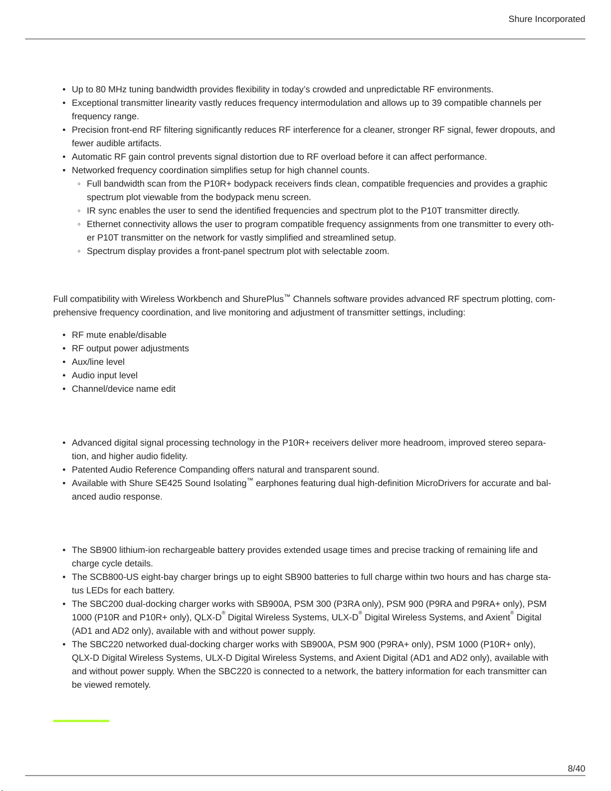
Components
•
P10T Rackmount Transmitter
•
P10R+ Bodypack Receiver (2)
•
Two 1/2 Wave Antennas
•
AA Batteries (4)
•
Antenna Cables (2)
•
IEC Power Cable and IEC Extension Cable
•
Ethernet Network Cable
•
Zippered Bag
Rackmount supplies:
•
2 antenna hole plugs
•
4 rack mounting screws with washers
Shure Incorporated
Quickstart Instructions
Rack Mount Transmitter
1.
Connect to a power outlet using the supplied power cable.
2.
Attach the supplied antennas to the antenna out BNC connectors.
9/40
Page 10
Shure Incorporated
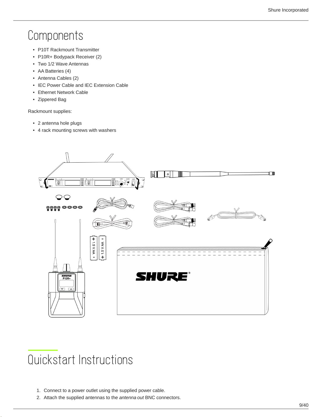
3.
Connect the audio source, such as the output of a mixer, to the audio inputs. You can use both input jacks or choose ei
ther one for a mono source.
4.
Switch RF off and power on.
5.
For mono (one input), access the Audio menu and select Mono.
Set the input sensitivity to match the source using the Util > Audio > INPUT setting.
6.
Adjust the audio source level so that, for the average input signal level, the top two yellow LEDs flicker and the lower
LEDs are solid. If the red clip LED illuminates and a warning appears on the LCD, the inputs are overdriven. Decrease
the audio input level to +4 dBu from the Audio menu. If the signal level is too low, change the input sensitivity to –10
dBV
10/40
Page 11
Shure Incorporated
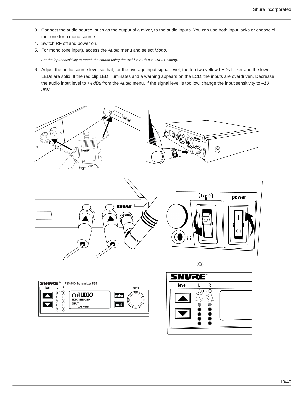
Bodypack
Open by pressing the latches on both sides and pulling. Insert the batteries or battery pack and attach antennas. Turn on using
the volume knob. The battery light illuminates.
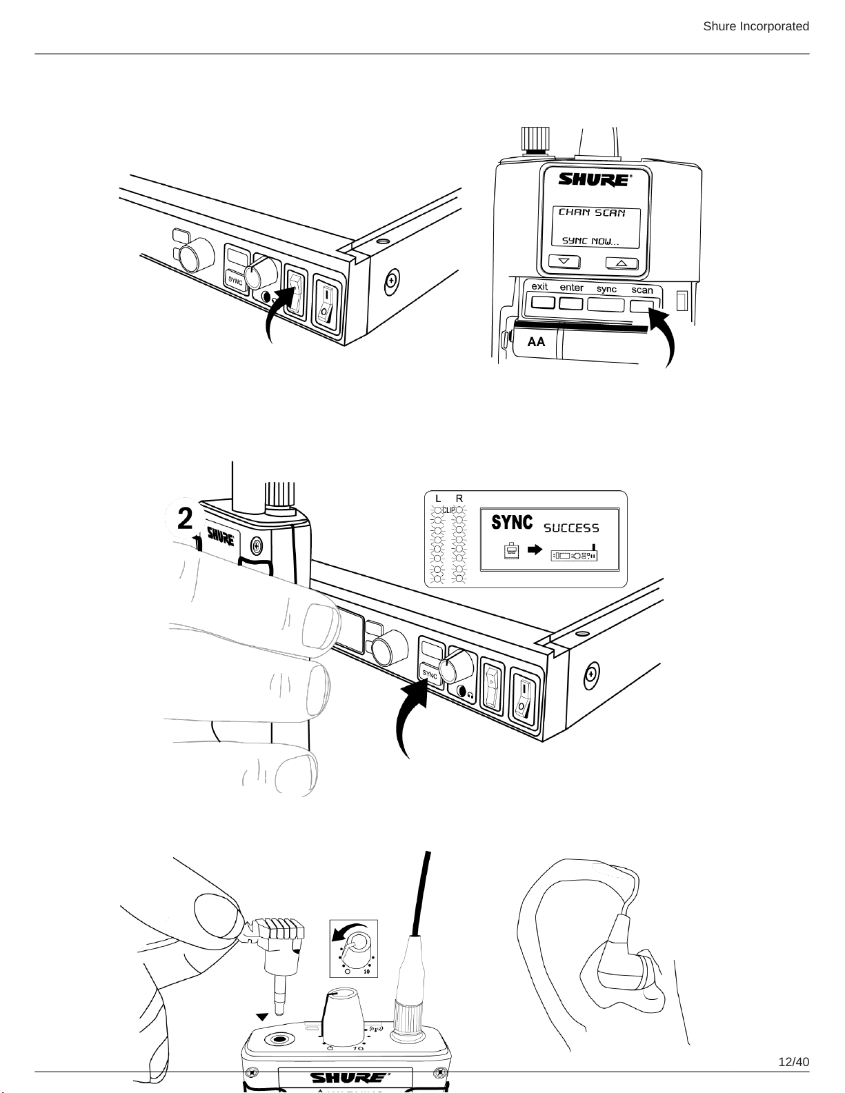
Scan and Sync
1.
On the bodypack, press the scan button. The display flashes SYNC NOW....
2.
Align the IR windows on the bodypack and rack unit, the IR window on the transmitter illuminates. Press the sync but
ton on the transmitter. The rack unit Level LEDs flash, and the screen displays SYNC SUCCESS.
3.
Turn the RF switch on. The blue RF LED illuminates on the bodypack to indicate that it is detecting the transmitter. The
bodypack also displays the RF signal strength (RF).
4.
Important: Turn bodypack volume down before plugging in earphones.
5.
Insert the earphones and slowly turn up the volume.
11/40
Page 12
Shure Incorporated
12/40
Page 13

Shure Incorporated
Important: Remove the protective film from the face of the transmitter or the IR sync may not work.
Front Panel Controls
① Sync Window
Align bodypack IR window with sync window on TX.
② RF Switch
Mutes RF output. For setting up multiple systems or adjusting settings without transmitting unwanted RF or audio signals.
③ Audio Indicators
Use the control wheel to adjust the audio so that, for the average input signal level, the top two yellow LEDs flicker and the
lower LEDs are solid. Press the enter button to save the value, exit to cancel. The red clip LED indicates the inputs are
overdriven. Reduce the level at the audio source or change the input sensitivity of the rack unit from the Audio > Input
menu.
④ Status Display and Controls
Use the navigation buttons to access the configuration menu. Push the control wheel to move the cursor to the next item.
Turn the control wheel to change a parameter—the enter button flashes. Press it to save the value. Press the exit button to
cancel changes and return to the previous menu.
⑤ Headphone Monitoring
The monitor control adjusts signal output to the 3.5 mm headphone jack. Push button to toggle between transmitters. Moni
tor clip LED indicates headphone audio is clipping.
⑥ Power Switch
Turns the unit on and off.
Rear Panel
⑦ Primary power switch
This switch disconnects power to the unit. It is not affected by the interface power lock in the Util menu. Only the front pow
er switch can be locked.
13/40
Page 14

Shure Incorporated
⑧ Power plug
AC mains power input, IEC Connector 100-240 Vac.
⑨ AC mains power passthrough
Use with an IEC extension cable to supply AC power to another device. Unswitched.
⑩ Antenna (BNC) port
Attach supplied antennas. If you are rack mounting, use a front panel or remote mounting kit from Shure.
⑪ loop out
Sends audio signal going into the transmitter to another device.
⑫ Audio Inputs
Connect to balanced or unbalanced outputs. Use either jack for mono input. Accepts male XLR or 6.35 mm (1/4-inch) TRS
plugs.
⑬ Ethernet Jack
Two-port RJ-45 Ethernet jack for connection to a network or computer.
Transmitter Menu Structure and Navigation
Home Screen
The home screen provides access to submenus and displays a summary of transmitter settings.
① Audio channel name
② Frequency setting
③ Group and Channel
④ Network Icon
⑤ Lock Icon
⑥ RF Power Level
⑦ Audio Level
⑧ Mix-mono or stereo
⑨ Aux/Line in
⑩ Submenus
⑪ TV Channel
14/40
Page 15

Radio Frequency (RF) Settings
Access the Radio menu to adjust the frequency and power at which the unit operates.
G
Group number. Each group contains channels selected to work well together in a single installation.
Shure Incorporated
Ch
Channel number. Sets the transmitter to a channel in the selected group.
888.888 MHz
Displays the frequency to which the transmitter is set. Frequency selection; adjustable in increments of 1MHz or 25kHz.
PWR
Power level at which the transmitter operates. Select from 10, 50, or 100 mW (power levels vary by region).
Custom
For creating custom frequency groups. See Custom Groups.
Audio Settings
Access the following settings from the Audio menu.
Input Level (
This changes the audio level for the inputs on the back of the rack transmitter.
Input
)
15/40
Page 16

Line
+4 dBu (line level)
Aux
–10 dBV (aux level)
Shure Incorporated
Audio Mode (
Stereo/MX
Transmits each input as a separate channel.
Mono
Combines both inputs into a single channel.
PTP
Set up the device for point-to-point wireless audio.
Output Level (
Adjust output level.
Receiver Synchronization Menu (
Mode
Level
)
)
Sync
)
Transferring Settings to the Bodypack During Sync (
RxSetup
)
16/40
Page 17

Shure Incorporated
Use this feature to store settings that will be transferred to the bodypack during a sync. By default, settings are unaffected by a
sync, indicated by the NoChange option.
Lock
ON: Locks the bodypack interface.
Off: Unlocks the bodypack interface.
Mode
Sets stereo (ST) or MixMode (MX).
Bal Mx
Sets balance for MixMode.
Bal St
Sets balance for stereo mode.
Gain
Switches between Standard and High gain modes.
The following settings are only available on legacy P9RA and P10R bodypack receivers. P9RA+ and P10R+ receivers will not be affected by these settings.
V Lim
Off: Turn volume limit off.
ON: Turn volume limit on.
Lim Val
Sets value for volume limit.
HiBoost
Sets value for high frequency boost.
Assign Audio Settings Using IR Sync (P10R+Setup)
Use these options to assign audio settings to P10R+ bodypack receivers during an IR sync. Legacy P10R receivers will not be
affected by these settings.
For additional information, see the Audio Settings section of this guide.
Downloading and Viewing Spectrum Scan Data (
Align the receiver and transmitter IR ports and press SyncScan to download spectrum scan data from the receiver.
After downloading data, the following options are available:
Deploy
Enters a submenu from which you can deploy open frequencies to all transmitters on the network.
Cursor
Enables the control wheel to move the cursor.
Spectrum
)
17/40
Page 18

Zoom
Enables the control wheel to zoom into graphic at cursor position.
Tip: Push the control wheel to toggle between cursor and zoom modes.
Sync
Press to sync the receiver and transmitter using the IR port.
Utility Settings
Channel Name
Shure Incorporated
Util > Channel Name
Turn control wheel to change channel name. You can set a different name for each channel on the device (this name is up
loaded to the bodypack with sync).
Display Settings
Util > Display
Change the look of the LCD panel from the display menu.
Brightness
Sets display brightness to high, low, or medium.
Disp. Invert
Changes display from light on dark to dark on light.
18/40
Page 19

Contrast
Use the control wheel to adjust contrast.
Interface Locks
Use these controls to lock or unlock power switch and front panel controls.
Power Switch
Util > Lock > Power Switch
Locked
Locks power switch.
Off
Unlocks power switch.
Front Panel
Shure Incorporated
Util > Lock > Front Panel
Locked
Locks the controls on the front panel for the selected transmitter.
Off
The front panel is unlocked.
Unlocking Front Panel
To unlock the front panel, select Util > Unlock
Network Setup
Use this menu to find, display and change how this device connects to the network. There is one set of network settings for
both transmitters.
Device Identification (Device)
Allows you to assign a display name. This applies to both channels on the device. To name each channel individually, use the
Channel Name setting.
Setup (Mode)
Automatic
Default setting for use with DHCP networks.
Manual
Manual IP addressing. Allows you to enter an IP address (IP) and subnet mask (SUB).
MAC
Displays MAC address for this device, view only, and there is only one MAC address for both transmitters.
19/40
Page 20

Reset
Manual mode only. Resets network settings to the factory defaults.
Find All Network Devices (Find All)
Lists all network devices.
•
Scroll to any of the listed devices and press Show Info to view information about that device.
•
Press Flash to flash the LEDS of all devices on network
•
Press Back to return to previous screen
Shure Incorporated
Additional Settings (
Product ID
Displays product serial number.
Reset All
Restores the values on all networked devices to factory default settings.
FW Update
Displays the receiver firmware version that is currently stored in the transmitter. Press Download to transfer the update to
a receiver through the IR port.
More
)
20/40
Page 21

Bodypack Receiver
Shure Incorporated
① Power Switch and Volume Control
Turns the bodypack on and off and adjusts earphone volume.
② 3.5 mm Earphone Jack
Insert earphones here.
③ Scan Button
Press the scan button to find an available frequency. Press and hold for two seconds to find the group with the most avail
able channels.
④ IR Window
For transmitting settings between bodypack and rack unit.
⑤ Battery Compartment
Requires 2 AA batteries or Shure rechargeable battery. Open by pressing the latches on both sides and pulling.
⑥ Menu buttons
Use in conjunction with the ▼▲ buttons to access the configuration menus.
21/40
Page 22

⑦ ▼▲ Buttons
Use to adjust the audio mix (in MixMode only), or in conjunction with the menu buttons to change settings.
⑧ LCD Screen
Displays current settings and menus.
⑨ Tri-Color Battery LED
Illuminates green, amber, or red to indicate battery power. When red, change battery immediately.
⑩ Blue RF LED
Indicates the bodypack is receiving a signal from the transmitter.
⑪ SMA Connector
For detachable antennas.
⑫ Removable AA Adapter
Shure Incorporated
Remove to use with a Shure SB900 rechargeable battery.
Note: To remove adapter, open door and slide out. To reinstall adapter, place over the clip and press, there will be an audible click when seated.
RF Settings
Access the following RF settings from the RADIO menu.
G
Group number. Each group contains channels selected to work well together in a single installation.
CH
Channel number. Sets the receiver to a channel in the selected group.
888.888 MHz
Displays the frequency to which the transmitter is set. Highlight and use the ▼▲ buttons to set the transmitter to a specific
frequency.
SQUELCH
Adjusts the squelch setting.
FULL SCAN
Performs spectrum scan and displays open frequencies in a graphical interface.
RF PAD
Attenuates antenna signals in 3 dB increments.
ANTENNA
Selection for single antenna operation. Disables diversity reception.
Audio Settings
Access the following audio settings from the Audio menu.
22/40
Page 23

Shure Incorporated
Output Mode (
STEREO
Receive left and right inputs as a stereo signal
MIXMODE
®
Set your receiver to combine the left and right channel for simultaneous listening in both ears or pan to listen to only the
left or right channel
MODE
)
Four-Band Parametric Equalizer (EQ)
The parametric equalizer is divided into four frequency bands: LOW, LOW MID, HIGH MID, and HIGH. When the EQ is en
abled, the following parameters are adjustable:
FREQUENCY
Select the center frequency of the band to boost/cut
Q
Adjusts the width and slope of the frequency band (measured in octaves)
GAIN
Adjustable in 2 dB increments from -6 dB (cut) to +6 dB (boost)
NOTE: HIGH and LOW are shelf filters, and therefore do not have adjustable Q widths. The HIGH shelf is fixed at 10 kHz; the LOW shelf is fixed at 100 Hz.
Volume Limiter (V
V LIM
Set a value (OFF to 48 dB, adjustable in 3 dB increments) to attenuate the highest possible volume level. Turning the vol
ume knob through its entire range of motion still affects volume; the limit simply narrows the range of dB adjustment.
LIM
)
Note: The volume limit does not compress the audio signal.
Volume Lock (V
P9RA+ and P10R+ only
LOCK
)
23/40
Page 24

ON
The volume is locked to the physical position of the volume knob
Shure Incorporated
Input EQ Preset (
Input EQ affects the signal after it is sent to the receiver, but before the headphone output, modifying the overall sound of the
entire system.
Match (default)
Matches the frequency response of legacy PSM receivers, allowing for matched audio with mixed-inventory setups
Flat
Offers a flat frequency response curve
Off
Audio bypasses input EQ
Balance (
BAL ST / BAL MX
Balance
▼▲ Buttons
BAL ST / BAL MIX
EQPre
)
)
Left and right balance for earphones when in stereo mode, or mix of left and right channel for MixMode
Utilities and Display Settings
Access the following settings from the UTILITIES menu.
CUEMODE
Enters CUEMODE to exit, press enter and select EXIT CUEMODE
DISPLAY
Change the display settings on the bodypack
CONTRAST
Sets display brightness to high, low, or medium.
LOCK PANEL
Locks all controls except power and volume.To unlock, press exit, select OFF, and press enter.
BATTERY
When using an SB900 - Shure rechargeable battery, the following information is displayed: Hrs: Min Left, temperature, Sta
tus, Cycle Count, and Health.
AUTO OFF
24/40
Page 25

Sets the time at which the receiver is powered off after entering power-save mode (when POWER SAVE is displayed on
the screen).
RESTORE
Returns receiver to factory default settings.
Battery Life
Approximate Hours Remaining (h:mm)
Shure Incorporated
Battery Indicator
Tri-Color
Battery
LED
Green 6:00 to 3:50 4:20 to 2:45 3:15 to 2:05
Green 3:50 to 2:50 2:45 to 2:00 2:05 to 1:30
Green 2:50 to 1:15 2:00 to 1:00 1:30 to 0:50
Green 1:15 to 0:25 1:00 to 0:20 0:50 to 0:20
Amber 0:25 to 0:15 0:20 to 0:10 0:20 to 0:10
Alkaline Shure SB900A Rechargeable Battery
Volume Level Volume Level
4 6 8 4 6 8
8:00
to
3:45
3:45
to
2:45
2:45
to
1:45
1:50
to
0:55
0:55
to
0:25
6:45 to 3:45 6:00 to 3:45
3:45 to 2:45 3:45 to 2:45
2:45 to 1:45 2:45 to 1:45
1:50 to 0:55 1:50 to 0:55
0:55 to 0:25 0:55 to 0:25
Red < 0:15 < 0:10 < 0:10 < 0:25 < 0:25 < 0:25
Total Battery Life 6:00 4:20 3:15 8:00 6:45 6:00
Power-save mode: When there are no earphones plugged in for 5 minutes, the receiver enters power-save mode to preserve
battery life. The LED slowly fades on/off in this mode and continues to display the color that represents the remaining battery
life.
Note: Battery life using Energizer brand AA Alkaline batteries and the following conditions:
•
Receiver audio set to V LIMIT = 0dB
•
Transmitter audio INPUT set to Line+4 dBu and Level set to −9 dB
•
Audio input to the transmitter: pink noise at +8.7 dBV
•
Audio output at receiver: 115 dB SPL in ear with SE425 earphones (impedance at 22 Ώ) set at volume level 4.
Note: Using lower-impedance earphones or ones with different sensitivity, different battery types, and higher gain settings in the PSM system may cause the
receiver battery life to be different than specified.
25/40
Page 26

Shure Incorporated
Pink noise is a signal with a frequency spectrum such that the power spectral density is inversely proportional to the frequency. In pink noise, each octave car
ries an equal amount of noise power.
Multiple System Setup
When setting up multiple systems, designate a single bodypack to scan for available frequencies and download them to all the
rack units.
The bodypack must be from the same frequency band as all the transmitters.
1.
Power on all the rack units. Turn off the RF. (This prevents them from interfering with the frequency scan.)
Note: Turn on all other wireless or digital devices as they would be during the performance or presentation (so the scan will detect and avoid any in
terferance they generate).
2.
Use the bodypack to scan for a group by pressing and holding the scan button for two seconds. The bodypack dis
plays the group and the number of available channels, and flashes SYNC NOW....
Important: Note the number of available channels. If you have more rack units than available channels, eliminate potential sources of interference
and try again, or call Shure Applications for assistance.
3.
Sync the bodypack with the first rack unit by aligning the IR windows and pressing sync.
4.
Press scan again on the bodypack to find the next available frequency.
5.
Sync the bodypack with the next rack unit.
6.
Repeat with all the rack units.
7.
Sync each performer's bodypack to its respective rack unit by aligning the IR windows and pressing snyc. DO NOT
press scan on the bodypacks.
8.
Turn on the RF on all rack units. The systems are ready to use.
CueMode
CueMode allows you to upload the name and frequency settings from multiple rack units and store them as a list on a single
bodypack. You can then, at any time, scroll through that list to hear the audio mix from each transmitter, just as each performer
does during a show.
CueMode lists are retained even if CueMode is exited, the bodypack is turned off, or batteries are removed.
Note: Set the channel frequency and assign display names for each transmitter before creating your CueMode list.
Adding Transmitters to the CueMode List
Note: The transmitter must be from the same frequency band as the bodypack.
1.
Open the battery door and press the enter button.
2.
From the main menu, scroll to UTILITIES and press enter. Select CueMode and press enter again.
3.
Align IR windows and press sync on the rack unit.
The LCD displays SYNC SUCCESS after frequency and name data are uploaded to the CueMode list. It also displays
the CueMode number for that transmitter and the total number of transmitters.
4.
Repeat the above step for each transmitter.
Note: Syncing while in CueMode does not change any of the settings on the bodypack.
26/40
Page 27

Auditioning Mixes
1.
Enter CueMode from the UTILITIES menu.
2.
Use the ▼▲ buttons to scroll through your CueMode list to hear the mixes.
Exiting CueMode
Exit CueMode by pressing enter and selecting EXIT CUEMODE.
Managing CueMode Mixes
While in Cue Mode, you can access the following menu by pressing enter:
REPLACE MIX
Select and press sync on a rack unit to upload new data for the current mix (for example, if you have changed the trans
mitter frequency).
Shure Incorporated
DELETE MIX
Removes the selected mix.
DELETE ALL
Removes all mixes.
EXIT CUEMODE
Exits CueMode and returns the bodypack to the previous frequency setting.
Frequency Scan
Use a frequency scan to analyze the RF environment for interference and identify available frequencies. There are three types
of scan:
•
Channel Scan Press the scan button on the bodypack. Finds the first available channel.
•
Group Scan Press and hold the scan button for two seconds. Finds the group with the greatest number of available chan
nels. (Each group contains a set of frequencies that are compatible when operating multiple systems in the same environ
ment.)
•
Full Scan From the bodypack menu select RADIO > FULL SCAN. Press RUN SCAN to initiate a full scan. Press SPEC
TRUM to view full results in a graphical display.
Note: When performing a frequency scan:
•
Turn off the RF on the transmitters for the systems you are setting up. (This prevents them from interfering with the fre
quency scan.)
•
Turn on potential sources of interference such as other wireless systems or devices, computers, CD players, large LED
panels, effects processors, and digital rack equipment so they are operating as they would be during the presentation or
performance (so the scan will detect and avoid any interference they generate).
27/40
Page 28

Shure Incorporated
Sync
You can transfer frequency settings in either direction: from the bodypack to the rack unit, or from the rack unit to the body
pack.
Note: You can also choose to transfer other settings to the bodypack during a sync, such as lock or mode settings, using the Sync > RxSetup menu on the
rack transmitter.
Downloading settings from the bodypack
1.
Press the scanbutton on the bodypack.
2.
Align the IR windows and press the syncbutton from the rack transmitter LCD menu while the bodypack display is flash
ing "SYNC NOW...".
The level LEDs on the rack unit flash.
Sending settings to the bodypack
1.
Press the Sync button on the rack transmitter to access the sync menu.
2.
Align the IR windows.
When properly aligned the IR window on the transmitter illuminates.
3.
Press Sync to transfer settings.
The blue LED on the bodypack flashes.
Creating Custom Groups
This feature allows you to create your own groups of frequencies.
Menu: Radio > Custom
1.
Turn the Control wheel to select a custom group from the Group menu. (U1, U2, etc.)
2.
Push the Control wheel to move to the Channel parameter and turn it to select a channel (01, 02, 03, etc.)
3.
Push the Control wheel to move to the Freq parameter and select a frequency for that channel.
4.
Push the Next menu key to select a frequency for the next channel in that group.
5.
Select Load to find all other devices of the same model and band on the network. Then press enter to deploy the cus
tom group list to all these devices.
This overwrites all existing custom groups.
6.
Clear deletes all custom groups for all devices on the network.
MixMode
Some performers need to hear more of their own voice or instrument, while others want to hear more of the band. With Mix
Mode, the performer creates their own mix using the balance control (▼▲ buttons) on the bodypack.
To use MixMode, send a solo mix of the performer to the L/CH1 input on the transmitter, and send a band mix to the R/CH2 in
put.
28/40
Page 29

Shure Incorporated
Set the performer's bodypack for MixMode. The bodypack combines the two signals and sends them to both earphones, while
the balance control on the bodypack adjusts the relative levels for each.
For IFB applications, send two independent program feeds into the L/CH1 and R/CH2 input of the transmitter. With MixMode,
the director or broadcast talent can listen to either feed using the balance control (▼▲ buttons) on the bodypack to pan to ei
ther audio signal.
LOOP Applications
Use LOOP OUT L (left) and R (right) outputs to send a copy of the audio signal going into the transmitter to other devices. Fol
lowing are a few of the many applications for these outputs.
Note: The input level control and the input pad do not affect the LOOP OUT signals.
MixMode for Multiple Systems
Configure each system for MixMode. From the mixing console, send a mix of the whole band to input 2 of the first transmitter.
Connect the LOOP OUT R output to the R/CH2 input of the next transmitter. Continue the chain with all the transmitters.
Next, create solo mixes for each performer. Send each mix to input 1 of the transmitter for that performer.
Floor Monitors
Send the audio from the LOOP outputs to onstage loudspeakers. The bodypack and the onstage monitors receive the same
audio signals.
Note: The LOOP audio outputs will not drive passive loudpeakers, and must be sent to a power amplifier or an active loudspeaker.
Recording Devices
To record a performance, connect the LOOP outputs to the inputs of a recording device.
Squelch
Squelch mutes audio output from the bodypack when the RF signal become noisy. While squelch is activated, the blue LED on
the bodypack turns off.
For most installations, squelch does not need adjustment, and it keeps the performer from hearing hiss or noise bursts if the
RF signal becomes compromised. However, in congested RF environments or in close proximity to sources of RF interference
(such as large LED video panels), the squelch may need to be lowered to prevent excessive audio dropouts. With lower
squelch settings, the performer may hear more noise or hiss, but will experience fewer audio dropouts.
Important: Before lowering squelch, first try to eliminate the problem by finding the best set of frequencies for your installation and removing potential sources
of interference.
Caution: Turning off or lowering the squelch setting can increase the noise level and cause discomfort to the performer:
•
Do not lower the squelch setting unless absolutely necessary.
•
Turn earphone volume to the lowest setting before adjusting squelch.
•
Do not change the squelch setting during a performance.
•
Turn up the transmitter level setting to make noise or hiss less noticeable.
29/40
Page 30

Shure Incorporated
Squelch Settings
HIGH (NORMAL) Default factory setting.
MID Moderately decreases the signal-to-noise ratio required to squelch the receiver.
LOW Greatly decreases the noise squelch threshold.
PILOT ONLY* Turns off noise squelch leaving only pilot squelch on.
NO SQUELCH*
* Symbol appears in dis
play window.
Turns off noise and pilot tone squelch. (Sometimes used as a debugging tool by
monitor engineers or RF coordinators to "listen" to the RF environment.)
Point-to-Point Wireless Audio
Use PTP mode to allow a P10T to transmit to a UHF-R receiver. This allows a transmitter and receiver setup where both units
are racked and powered by AC.
For more information visit: www.shure.com/americas/products/personal-monitor-systems
Ethernet Connection
Each transmitter has an RJ-45 port on the back for connecting to other transmitters over an Ethernet network. Networking
transmitters allows you to automatically set frequencies for all the transmitters with a single group scan command.
Add transmitters to a network using the default automatic network setting (Util > Network > Mode > Automatic):
1.
Connect transmitters to an Ethernet router with DHCP service.
2.
Use Ethernet switches to extend the network for larger installations.
30/40
Page 31

Shure Incorporated
3. Connect transmitters in series.
Accessing the Network with a Computer
You can control and monitor all networked transmitters through a computer running Shure Wireless Workbench software, Ver
sion 6 or later. If using the default automatic network setting, make sure your computer is configured for DHCP.
Note: Some security software or firewall settings on your computer can prevent you from connecting to the transmitter. If using firewall software, allow connec
tions on port 2201.
Static IP Addressing
Static IP addressing is also supported. An IP address can be assigned through the network menu (Util > Network > Mode >
Manual).
Note: Dual transmitters use a single IP address, which may be set through either LCD interface.
Connecting Transmitters
Router with DHCP
Extended Network
31/40
Page 32

Shure Incorporated
Direct Connection to Computer
Spectrum Scan
Use this feature to scan the full RF spectrum for potential sources of interference and deploy open frequencies to all receivers
on the network. A graphical representation of the scan data may be viewed on both the transmitter and receiver. This allows
you to scroll through the graph to reveal details about the frequency and strength of the interfering signals.
Scanning and Deploying Frequencies
1.
Turn off RF on all receivers.
2.
Collect the scan data. From the bodypack receiver MAIN MENU, select RADIO > FULL SCAN > RUN SCAN
The receiver displays SPECTRUM SCAN and scans the full spectrum.
3.
Load the scan data from the bodypack receiver to the rack transmitter. Align the IR windows and press Sync >
Spectrum > SyncScan
The receiver displays the scan data as a graph and gives options for viewing and deploying.
4.
Search network for devices. From the rack transmitter Sync > Spectrum menu, press Deploy.
The rack transmitter searches the network for all available transmitters.
5.
Choose a group. Use the control wheel to select from the available groups.
The number of open frequencies for each group is displayed next to Open Frequencies.
6.
Deploy frequencies. Press the flashing enter button to deploy frequencies to all channels.
The LEDs flash on all affected channels.
Viewing Spectrum Data
From the Bodypack Receiver
MAIN MENU > RADIO > FULL SCAN > SPECTRUM
•
Adjust the cursor position using the ▼▲ keys.
•
Press enter to zoom in at the cursor position. Press exit to zoom out.
•
Press scan to display frequency and power of signal at the cursor position.
From the Rack Transmitter
Sync > Spectrum
•
Adjust the cursor position by pressing Cursor and using the control wheel.
32/40
Page 33

Shure Incorporated
•
Frequency and power of signal at the cursor position is displayed at the top of the screen.
•
Press Zoom and use the control wheel to zoom in and out.
Updating Receiver Firmware
Use the following steps to update the firmware on a bodypack receiver.
1.
Use the WWB update manager to download the receiver firmware to the rack transmitter.
2.
On the transmitter, navigate to the Util > More > FW Update menu.
3.
Align the receiver and transmitter IR ports and press Download. The download begins, which can take 50 seconds or
longer.
Once the download is complete, the receiver automatically begins the firmware update, which overwrites the existing firmware.
CAUTION! Do not turn off the receiver until the update is complete.
Specifications
PSM 1000
RF Carrier Range
470–952 MHz
varies by region
Compatible Frequencies
Per band
39
Tuning Bandwidth
72–80 MHz
Note: varies by region
Operating Range
environment dependent
90 m (300 ft)
Audio Frequency Response
35 Hz –15 kHz (±1 dB)
Signal-To-Noise Ratio
A-Weighted
90 dB (typical)
Total Harmonic Distortion
ref. ±34 kHz deviation @1 kHz
<0.5% (typical)
33/40
Page 34

Companding
Patented Shure Audio Reference Companding
Spurious Rejection
ref. 12dB SINAD
>80 dB (typical)
Frequency Stability
±2.5 ppm
MPX Pilot Tone
19 kHz (±0.3 kHz)
Modulation
FM*, MPX Stereo
*ref. ±34 kHz deviation @1 kHz
Shure Incorporated
Operating Temperature
-18°C to +57°C
P10T
RF Output Power
selectable: 10, 50, 100 mW (+20 dBm)
RF Output Impedance
50 Ω (typical)
Net Weight
4.7 kg (10.4) lbs
Dimensions
44 x 483 x 343 mm (1.7 x 19.0 x 13.5 in.), H x W x D
Power Requirement
Input
100–240 V AC, 50/60 Hz, 0.5 A max.
(5.5, with outlet loaded)
Output
Audio Input
Connector Type
Combination XLR and 6.35 mm (1/4") TRS
100–240 V AC, 50/60 Hz, 5 A max.,
unswitched
34/40
Page 35
Polarity
Shure Incorporated
XLR
6.35 mm (1/4") TRS Tip positive with respect to ring
Noninverting (pin 2 positive with re
spect to pin 3)
Configuration
Electronically balanced
Impedance
70.2 kΩ (actual)
Nominal Input Level
switchable: +4 dBu, –10 dBV
Maximum Input Level
+4 dBu +29.2 dBu
-10 dBV +12.2 dBu
Pin Assignments
XLR 1=ground, 2=hot, 3=cold
6.35 mm (1/4") TRS Tip=hot, Ring=cold, Sleeve=ground
Phantom Power Protection
Up to 60 V DC
Audio Output
Connector Type
6.35 mm (1/4") TRS
Configuration
Electronically balanced
Impedance
Connected directly to inputs
P10R+
Tri-Band RF Filtering
–3 dB at 30.5 MHz from the center frequency of each band
Active RF Gain Control
31 dB
Adjusts RF sensitivity to provide more RF dynamic range
35/40
Page 36

Active RF Sensitivity
at 20 dB SINAD
2.2 µV
Image Rejection
>90 dB
Adjacent Channel Rejection
>70 dB
Latency
0.37ms
Squelch Threshold
22 dB SINAD (±3 dB)
default setting
Shure Incorporated
Intermodulation Attenuation
>70 dB
Blocking
>80 dB
Audio Output Power
1 kHz at Less than 1% distortion, Maximum Headphone Output Power, at 16 Ω
100 mW (per output)
Minimum Load Impedance
4 Ω
Output Impedance
<1 Ω
4-band Parametric EQ
Low Shelf Selectable Gain: ±2 dB, ±4 dB, ±6 dB @ 100 Hz
Low Mid
Selectable Gain: ±2 dB, ±4 dB, ±6 dB at 160 Hz, 250 Hz,
400 Hz, 500 Hz, 630 Hz Selectable Q: 0.7, 1.4, 2.9, 5.0, 11.5
High Mid
High Shelf Selectable Gain: ±2 dB, ±4 dB, ±6 dB @ 10 kHz
Selectable Gain: ±2 dB, ±4 dB, ±6 dB at 1 kHz, 1.6 kHz, 2.
5 kHz, 4 kHz, 6.3 kHz Selectable Q: 0.7, 1.4, 2.9, 5.0, 11.5
Volume Limiter
Selectable: OFF (0 dB)to -48 dB in 3 dB steps
Volume Lock
Selectable: 0 dB to -70 dB
36/40
Page 37

Limits volume adjustment knob. Selected value analogous to volume knob increment.
Net Weight
158 g (Without Battery)
Dimensions
99 x 66 x 23 mm (3.9 in. x 2.6 in. x 0.9 in.) H x W x D
Battery Life
4–6 hours (continuous use) AA batteries
Furnished Accessories
Omnidirectional Whip Antenna, Yellow Tip (470-542 MHz) UA700
Omnidirectional Whip Antenna, Gray Tip (540-626 MHz) UA710
Shure Incorporated
Omnidirectional Whip Antenna, Black Tip (596-692 MHz) UA720
Omnidirectional Whip Antenna, Blue Tip (670-830 MHz) UA730
Omnidirectional Whip Antenna, Red Tip (830-952 MHz) UA740
1/2 Wave Omnidirectional Receiver Antenna for improved wireless signal reception UA8
Antenna extension cables (2) 95B9023
Carrying/Storage Bag 95A2313
Hardware Kit (Rack mounting Screws)Hardware kit 90XN1371
Bumper Kit 90B8977
AA battery adapter 65A15224
Optional Accessories
Passive Directional Antenna 470-952 MHz. Includes 10 foot BNC to BNC cable. PA805SWB
PWS Helical Antenna, 480-900 MHz HA-8089
PWS Domed Helical Antenna, 480-900 MHz HA-8091
Wideband Omnidirectional Antenna (470-1100 MHz) UA860SWB
2 ft. BNC-BNC Coaxial Cable UA802
6 foot (1.8m) BNC to BNC Coaxial Cable for Remote Antenna Mounting for ULX
Wireless System
UA806
37/40
Page 38

25 ft. BNC-BNC Coaxial Cable UA825
50 ft. BNC-BNC Coaxial Cable UA850
100 ft. BNC-BNC Coaxial Cable UA8100
Shure Incorporated
4to1 antenna comber with power distribution to 4 transmitters (better RF perfor
mance and eliminates need for external power supply)
8-to-1 antenna combiner for better RF performance PA821B
Coiled IFB Earphone Cable for Shure Earphones EAC-IFB
PA421B
Frequency Range and Transmitter Output Power
Band Range Output Power (mW)
G10 470-542 10/50/100
G10E 470-542 10/50/100
G10J 470-542 6/10
G11 479-542 10
G62 510-530 10
H8Z 518-582 10/50
H22 518-584 10**/50/100
J8 554-626 10/50/100
J8A 554-608 10/50/100
614-616 10*
J8E 554-626 10/50/100
J8J 554-626 6/10
K10E 596-668 10/50/100
L8 626-698 10/50/100
L8A 653-657 10
657-663 10*
L8E 626-698 10/50/100
L8J 626-698 6/10
L9E 670-742 10/50/100
L11J 670-714 6/10
38/40
Page 39

Shure Incorporated
Band Range Output Power (mW)
M19 694-703 10/50
P8 710-790 10/50/100
Q12 748-758 10/50
Q21 710-787 10/50/100
Q22E 750-822 10/50/100
R27 794-806 10/50
X1 944-952 10/50/100
X7 925-937.5 10
NOTE: This Radio equipment is intended for use in musical professional entertainment and similar applications. This Radio apparatus may be capable of oper
ating on some frequencies not authorized in your region. Please contact your national authority to obtain information on authorized frequencies and RF power
levels for wireless microphone products.
WARNING: As of January 01, 2019 the use of radio transmitters in the bands 694 - 823 MHz is prohibited.
Certifications
P10R+
Approved under the Declaration of Conformity (DoC) provision of FCC Part 15.
Certified in Canada by ISED to RSS-123.
P10T
Certified under FCC Part 74.
*Certified under FCC Part 15.
**Certified under FCC Part 15 and Part 74.
Certified by ISED in Canada under RSS-123 and RSS-102.
Meets essential requirements of the following European Directives:
•
WEEE Directive 2012/19/EU, as amended by 2008/34/EC
•
RoHS Directive EU 2015/863
Note: Please follow your regional recycling scheme for batteries and electronic waste
This product meets the Essential Requirements of all relevant European directives and is eligible for CE marking.
Hereby, Shure Incorporated declares that the radio equipment is in compliance with Directive 2014/53/EU. The full text of the
EU declaration of conformity is available at the following internet address: http://www.shure.com/europe/compliance
Authorized European representative:
Shure Europe GmbH
Headquarters Europe, Middle East & Africa
Department: EMEA Approval
Jakob-Dieffenbacher-Str. 12
75031 Eppingen, Germany
39/40
Page 40

Phone: +49-7262-92 49 0
Fax: +49-7262-92 49 11 4
Email: EMEAsupport@shure.de
Shure Incorporated
40/40
 Loading...