

Page 1
GLX-D® ADVANCED DIGITAL WIRELESS
GLXD4R RECEIVER
USER GUIDE
Le Guide de l’Utilisateur
Guia del Usuario
Manual do Usuário
© 2017 Shure Incorporated
27A32874 (Rev. 3)
Printed in China
Page 2

Page 3
IMPORTANT SAFETY INSTRUCTIONS
1. READ these instructions.
2. KEEP these instructions.
3. HEED all warnings.
4. FOLLOW all instructions.
5. DO NOT use this apparatus near water.
6. CLEAN ONLY with dry cloth.
7. DO NOT block any ventilation openings. Allow sufficient distances for adequate ventilation and install in accordance with the manufacturer’s instructions.
8. DO NOT install near any heat sources such as open flames, radiators,
heat registers, stoves, or other apparatus (including amplifiers) that
produce heat. Do not place any open flame sources on the product.
9. DO NOT defeat the safety purpose of the polarized or grounding type plug. A polarized plug has two blades with one wider
than the other. A grounding type plug has two blades and a third
grounding prong. The wider blade or the third prong are provided
for your safety. If the provided plug does not fit into your outlet,
consult an electrician for replacement of the obsolete outlet.
10. PROTECT the power cord from being walked on or
pinched, particularly at plugs, convenience receptacles,
and the point where they exit from the apparatus.
11. ONLY USE attachments/accessories specified by the manufacturer.
12. USE only with a cart, stand, tripod, bracket, or table specified by the manufacturer, or sold with the apparatus.
When a cart is used, use caution when moving the cart/
apparatus combination to avoid injury from tip-over.
13. UNPLUG this apparatus during lightning storms
or when unused for long periods of time.
14. REFER all servicing to qualified service personnel. Servicing is required when the apparatus has been damaged in any way, such as
power supply cord or plug is damaged, liquid has been spilled or objects have fallen into the apparatus, the apparatus has been exposed
to rain or moisture, does not operate normally, or has been dropped.
15. DO NOT expose the apparatus to dripping and splashing. DO NOT
put objects filled with liquids, such as vases, on the apparatus.
16. The MAINS plug or an appliance coupler shall remain readily operable.
17. The airborne noise of the Apparatus does not exceed 70dB (A).
18. Apparatus with CLASS I construction shall be connected to a
MAINS socket outlet with a protective earthing connection.
19. To reduce the risk of fire or electric shock, do not expose this apparatus to rain or moisture.
20. Do not attempt to modify this product. Doing so could result in personal injury and/or product failure.
21. Operate this product within its specified operating temperature range.
Explanation of Symbols
Caution: risk of electric shock
Caution: risk of danger (See note.)
Direct current
Alternating current
On (Supply)
Equipment protected throughout by DOUBLE
INSULATION or REINFORCED INSULATION
Stand-by
Equipment should not be disposed of in the normal
waste stream
WARNING: Voltages in this equipment are hazardous to life. No user-serviceable parts inside.
Refer all servicing to qualified service personnel. The safety certifications do not apply when the
operating voltage is changed from the factory setting.
WARNING: Battery packs shall not be exposed to excessive heat such as
sunshine, fire, or the like.
WARNING: Danger of explosion if incorrect battery replaced. Operate
only with AA batteries.
WARNING
• Battery packs may explode or release toxic materials. Risk of fire or
burns. Do not open, crush, modify, disassemble, heat above 140°F
(60°C), or incinerate
• Follow instructions from manufacturer
• Never put batteries in mouth. If swallowed, contact your physician or
local poison control center
• Do not short circuit; may cause burns or catch fire
• Do not charge or use battery packs with other than specified Shure
products
• Dispose of battery packs properly. Check with local vendor for proper
disposal of used battery packs
Note:
• This equipment is intended to be used in professional audio
applications.
• EMC conformance is based on the use of supplied and recommended cable types. The use of other cable types may degrade EMC
performance.
• Use this battery charger only with the Shure charging modules and
battery packs for which it is designed. Use with other than the specified
modules and battery packs may increase the risk of fire or explosion.
• Changes or modifications not expressly approved by Shure
Incorporated could void your authority to operate this equipment.
Note: Use only with the included power supply or a Shureapproved equivalent.
WARNING: This product contains a chemical known to the State of
California to cause cancer and birth defects or other reproductive
harm.
Page 4
System Overview
GLX-D Advanced Digital Wireless Systems combine Automatic Frequency Management technology with a rack mountable metal receiver, rechargeable
lithium-ion batteries, world-renowned microphones, and unparalleled design and construction. New GLX-D Advanced Frequency Managers (available
separately) connect multiple GLXD4R receiver systems for increased channel count and improved RF reliability, consolidating RF to one pair of antennas. New antenna accessories help improve reception by letting you mount antennas closer to transmitters, with directional reception for improved performance. Available in a variety of bodypack and handheld configurations, GLX-D Advanced Digital Wireless sets the standard for ease of operation and
digital audio clarity.
Features
• Exceptional digital audio clarity
• Operates in globally unlicensed 2.4 GHz spectrum
• Optional GLX-D Frequency Manager allows operation of up to 11
systems
• New antenna accessories for remote mounting and improved reception
• Half-rack size and metal chassis
• Rechargeable batteries deliver cost efficiency and up to 16 hours of
runtime
• Adjustable transmitter gain to optimize audio signal
• Automatically moves away from interference without audio interruption
• RF back-channel for remote control of transmitter functions
• Automatic transmitter power-off to conserve battery life when transmitter is not in use
Furnished Accessories
Reverse SMA Bulkhead Adapters, lockwasher, nut (2) 95A32436
USB Cable, Type A to Micro-B 95A21651
0.6 m (2 ft.) Reverse SMA Cable (2) UA802-RSMA
Power Supply PS43
Shure Lithium-Ion Rechargeable Battery SB902
Optional Accessories
GLX-D Frequency Manager UA846Z2-LC
Passive Directional Antenna 2.4 GHz PA805Z2-RSMA
Reverse SMA Passive Antenna Splitter (900 MHz
ISM, DECT, 2.4 GHz)
Wall Mount for PA805Z2-RSMA and UA8-2.4GHZ UA505-RSMA
1/2 Wave Antenna, 45 deg. (2.4 GHz) UA8-2.4GHZ
0.6 m (2 ft.) Reverse SMA Cable UA802-RSMA
1.8 m (6 ft.) Reverse SMA Cable UA806-RSMA
7.6 m (25 ft.) Reverse SMA Cable UA825-RSMA
15.2 m (50 ft.) Reverse SMA Cable UA850-RSMA
30.4 m (100 ft.) Reverse SMA Cable UA8100-RSMA
Reverse SMA Bulkhead Adapters 95A32436
Stand Alone Single Battery Charger SBC10-902
Car Battery Charger SBC-CAR
UA221-RSMA
Quick Start for Single Receiver
To reduce set-up time, the transmitter and receiver automatically link to form an audio channel the first time they are powered on and never have to be
linked again.
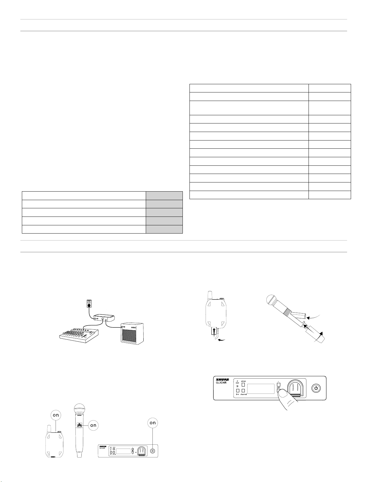
Step ①
Connect power supply to the receiver and plug cord into an AC power
source. Connect the audio output to an amplifier or mixer.
Step ③
Turn on the transmitter and receiver. The blue rf LED will flash while
the transmitter and receiver form a link. The rf LED turns solid blue
when the link has successfully formed.
Note: The transmitter and receiver will remain linked for future usage. At power-up, the blue rf LED and transmitter LED will illuminate, skipping the linking
step.
Step ②
Install charged transmitter batteries.
Step ④
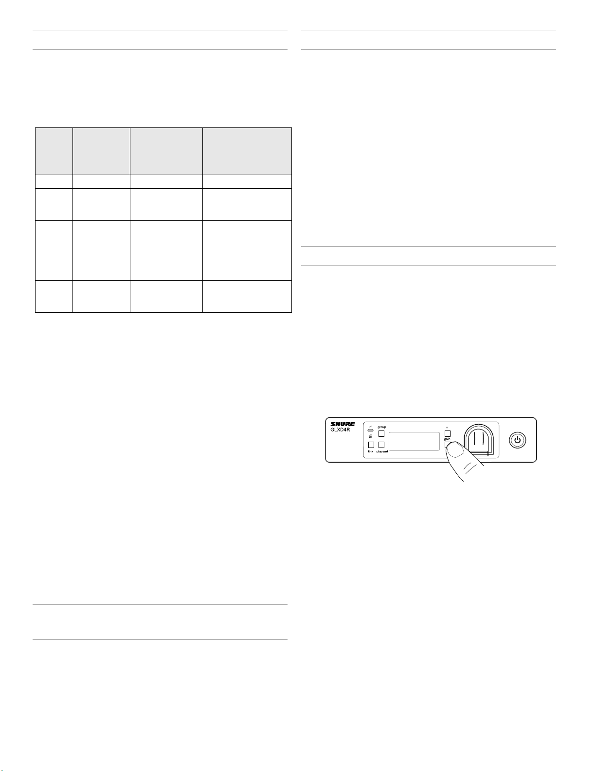
Check the audio and adjust the gain if necessary.
4
Page 5
Receiver Controls and Connectors
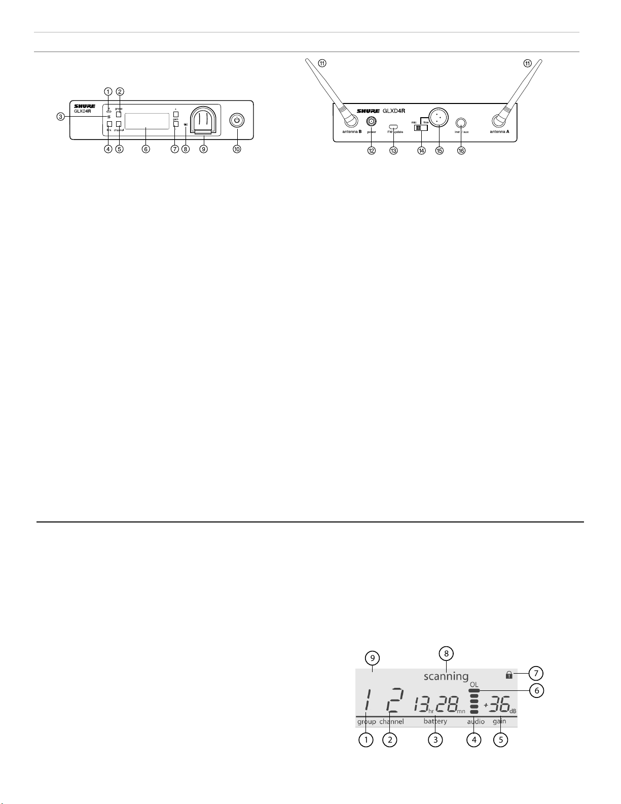
Front Panel
Rear Panel
① RF Status LED
- ON = Linked transmitter is on.
- Flashing = Searching for transmitter.
- OFF = Linked transmitter off or transmitter unlinked.
② Group Button
Press and hold for two seconds to enable manual group edit.
③ Data Sync LED
- ON = Data sync is on (receiver connected to GLX-D Frequency
Manager).
- Flashing = Searching for frequencies.
- OFF = Data sync is off (receiver not connected to GLX-D Frequency
Manager).
④ Link Button
Press to manually link receiver to a transmitter or to activate the
remote ID function.
⑤ Channel
- Press to start a channel scan.
- Press and hold for two seconds to enable manual channel edit.
⑥ LCD Screen
Displays receiver and transmitter status.
⑦ Gain Buttons
Press to increase or decrease transmitter gain in 1 dB increments.
⑧ Battery Charging Indicator
Illuminates when battery is in charging bay:
- Red = Battery charging.
- Green Flashing = Battery charge at 90%.
- Green = Battery charged.
- Amber Flashing = Charging error, replace battery.
⑨ Battery Charging Bay
Charges transmitter battery if receiver is plugged in to power outlet.
⑩ Power Button
Powers the unit on and off.
⑪ Antenna
Two antennas per receiver. Antennas pick up the signal from the
transmitter.
⑫ Power Supply Jack
Connect the supplied 15 V DC external power supply.
⑬ Firmware Update
Connect to computer to download firmware updates.
⑭ Mic/Line Switch
Sets XLR output level to microphone or line level.
⑮ XLR Audio Output
Supplies microphone-level or line-level audio output.
⑯ Inst/Aux Out
TRS ¼" (6.35mm) audio output. Connect to mixers, recorders, and
amplifiers.
Receiver Screen
① Group
Displays the selected group.
② Channel
Displays the selected channel.
③ Transmitter Battery Runtime
Displays remaining battery life in hours and minutes.
Alternatively displays the following battery status:
- CALC = battery life calculation
- Lo = battery life less than 15 minutes
- Err = replace battery
④ Audio Meter
Indicates audio signal level and peaks.
⑤ Gain
Displays transmitter gain settings (dB).
⑥ OL Indicator
Indicates audio overload, reduce gain.
⑦ Transmitter Locked
Displayed when linked transmitter controls are locked.
⑧ Scanning
Indicates a scan is in progress.
⑨ Auto
Indicates that the selected group has backup channels available.
auto
5
Page 6
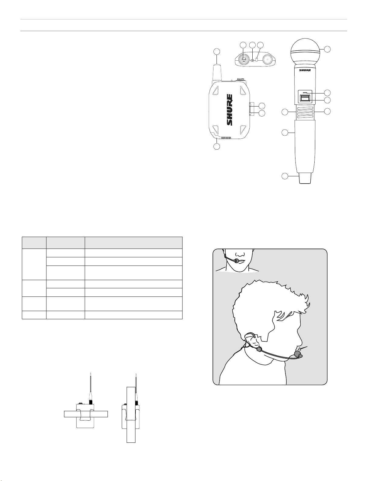
Transmitters
13 mm
(.5 in.)
① Antenna
Carries wireless signal.
② Status LED
LED color and state indicate transmitter status.
③ Power Switch
Turns the transmitter on/off.
④ TA4M Input Jack
Connects to a 4-Pin mini connector (TA4F) microphone or instrument
cable.
⑤ Micro USB Charging Port
Connect to USB battery charger.
⑥ Link Button
- Press and hold within 5 seconds of power-on to manually link with
receiver
- Press momentarily to activate Remote ID function
⑦ Battery Compartment
Holds 1 Shure rechargeable battery.
⑧ Microphone Cartridge
GLXD-2 transmitter models are available with the following cartridge
types: SM58, Beta 58, SM86, Beta 87A.
23
4
1
7
off on
GLXD2
on
5
6
6
7
1
8
2
3
5
Transmitter Status LED
LED is green during normal operation.
LED color or flashing indicates a change in transmitter status as shown in
the following table:
Color State Status
Green Flashing (slow) transmitter attempting relink with receiver
Flashing (fast) unlinked transmitter searching for receiver
Flashes 3
times
indicates locked transmitter when power
switch is pressed
Red On battery life < 1 hour
Flashing battery life < 30 minutes
Red/
Flashing remote ID active
Green
Amber Flashing battery error, replace battery
Wearing the Bodypack Transmitter
Clip the transmitter to a belt or slide a guitar strap through the transmitter
clip as shown.
For best results, the belt should be pressed against the base of the clip.
Wearing the Headworn Microphone
• Position the headworn microphone 13 mm (1/2 in.) from the corner of
your mouth.
• Position lavalier and headworn microphones so that clothing, jewelry, or
other items do not bump or rub against the microphone.
Correct Microphone Placement
• Hold the microphone within 12 inches from the sound source.
• For a warmer sound with increased bass presence, move the microphone closer to the sound source.
• Do not cover grille with hand.
6
Page 7
Batteries and Charging
GLX-D transmitters are powered by Shure SB902 lithium-ion rechargeable batteries. Advanced battery chemistry maximizes runtimes with zero memory
effects, eliminating the need to discharge batteries prior to charging.
When not in use, recommended battery storage temperature is 10°C (50°F) to 25°C (77°F).
Note: The transmitter will not pass RF or audio signals when connected to the charging cable.
The following battery charging options are available:
Receiver Charging Bay
The receiver's built-in charging bay will
charge transmitter batteries when receiver
is plugged in to power outlet.
1. Insert the battery into
the charging bay.
2. Monitor the battery charging indicator on the front panel.
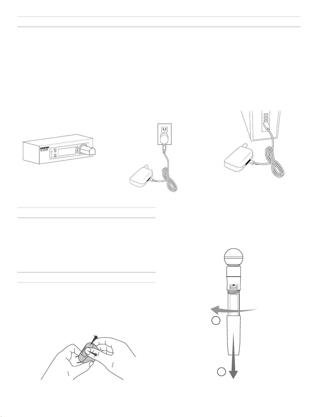
Charging from an AC Power
Source
1. Plug the charging cable into the
charging port on the transmitter.
2. Plug the charging cable into
an AC power source.
LED Status During Charging
The following LED states indicate battery status when the transmitter is
connected to a charger:
• Green = charging complete
• Green Flashing = battery charge > 90%
• Red = battery charging
• Amber Flashing = battery error, replace battery
Charging from a USB Port
1. Plug the USB charging cable into the
charging port on the transmitter.
2. Plug the cable into a standard USB port.
Handheld Transmitter
1. Unscrew and remove the battery cover.
2. Place the battery into the transmitter.
3. Replace and tighten the battery cover.
Installing Transmitter Batteries
Bodypack Transmitter
1. Move the locking lever to the open position and slide the battery door open.
2. Place the battery into the transmitter.
3. Close the battery door and slide the latch to lock.
1
2
7
Page 8
Charging Times and Transmitter Runtimes
Use the following table to determine approximate battery runtime based on the duration of charging time. Times shown are in hours and minutes. GLX-D
transmitters automatically power-off after approximately 1 hour to conserve battery life if the signal from a linked receiver is not detected.
Receiver Bay or AC Power
Source Charging
0:15 0:30 up to 1:30
0:30 1:00 up to 3:00
1:00 2:00 up to 6:00
3:00 4:00 up to 16:00*
*Storage time or excessive heat will reduce maximum runtime.
Note: If receiver is powered off and remains plugged in, battery will continue charging.
USB Connection
Charging
Transmitter
Runtime
Important Tips for Care and Storage of Shure Rechargeable Batteries
Proper care and storage of Shure batteries results in reliable performance and ensures a long lifetime.
• Always store batteries and transmitters at room temperature
• Ideally, batteries should be charged to approximately 40% of capacity for long-term storage
• During storage, check batteries every 6 months and recharge to 40% of capacity as needed
2.4 GHz Spectrum Overview
GLX-D operates within the 2.4GHz ISM band which is utilized by Wi-Fi, Bluetooth, and other wireless devices. The benefit of 2.4GHz is that it’s a global
band that can be used anywhere in the world, license free.
Overcoming the Challenges of 2.4 GHz
The challenge of 2.4 GHz is that Wi-Fi traffic can be unpredictable. GLX-D
meets these challenges in the following ways:
• Prioritizes and transmits on the best three frequencies per channel
(choosing from a pool of six frequencies across the 2.4 GHz band)
• Seamlessly moves away from interference to backup frequencies without audio interruption
• Optional GLX-D Frequency Manager improves RF reliability for systems
with more than two receivers
• Continuously scans during usage to rank all frequencies (both current
and backup frequencies)
• Antenna mounting accessories and directional antennas (available
separately) help reduce transmitter-to-antenna distance and connect to
antenna splitter
Coexisting with Wi-Fi
If you plan to use Wi-Fi during a performance, turn on Wi-Fi devices prior
to turning on GLX-D and scanning for the best channel. GLX-D detects
and avoids other Wi-Fi traffic by scanning the entire 2.4 GHz environment
and selecting the three best frequencies to transmit on. This method
avoids Wi-Fi signals and results in reliable performance for your GLX-D
wireless system.
“Bursting” Wi-Fi is harder to detect as it is periodic; however, because
GLX-D only repeats the most important information, even bursts at very
high levels don’t have an effect on your audio performance.
Challenging Wireless Environments
Some environments are more difficult than others for 2.4 GHz wireless
system performance. Additionally, body absorption has a greater impact in
the 2.4 GHz spectrum compared to the UHF spectrum. The simplest solution in many cases is to reduce transmitter-to-receiver distance by placing
receivers on the stage with a clear line of sight. You can also mount antennas remotely using Shure directional antennas to reduce transmitter-to-antenna distance.
Challenging environments include:
• Areas with few reflective surfaces such as:
- Outdoors
- Buildings with very high ceilings
• Three or more GLXD4R receivers in use and not connected to a GLX-D
Frequency Manager
• Areas with a strong Wi-Fi presence
• 2.4 GHz systems from other manufacturers in use
Note: Unlike analog TV band wireless system which typically use the
same type of transmissions across manufacturers, all 2.4 GHz wireless
currently on the market use different variations of wireless transmission.
These differences make it more difficult to mix and match 2.4 GHz systems from multiple manufacturers, as can be done with TV band wireless
solutions.
8
Page 9
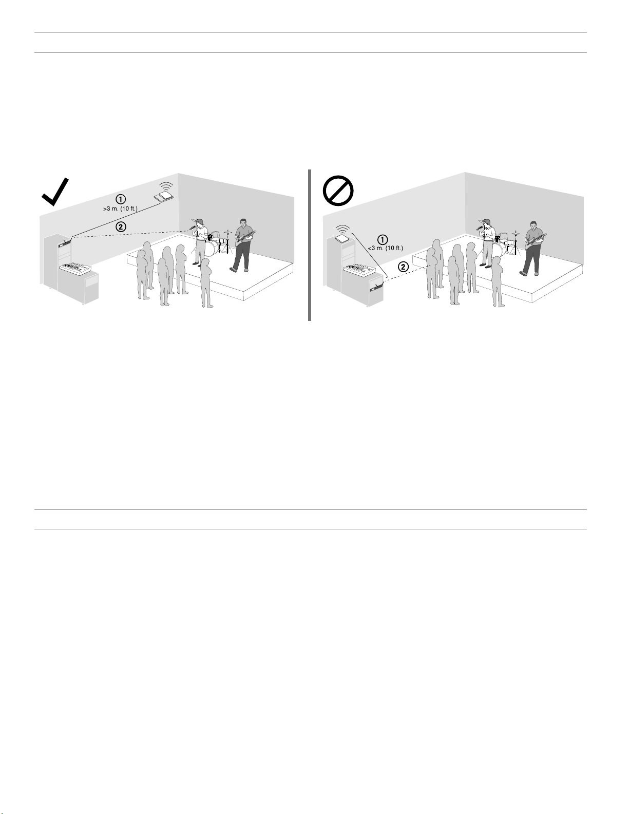
Tips to Improve Wireless System Performance
If you encounter interference or dropouts, try the following suggestions:
1. Place receiver at least 3 meters (10 feet) away from Wi-Fi access points, computers, or other active 2.4 GHz sources.
- Avoid heavy Wi-Fi traffic activities such as downloading large files or viewing a movie.
- Turn on any Wi-Fi prior to turning on GLX-D and scanning for the best channel.
2. Reduce transmitter-to-receiver distance by placing receivers on stage or above the audience with a clear line of sight to the transmitter.
- Move receiver to the top of the equipment rack for a clear line of sight.
- Mount antennas remotely to place closer to transmitters and improve RF reliability if receivers cannot be moved closer.
- Make sure people do not block the line of sight between receiver and transmitter.
Additional Tips
• Do not place competitive 2.4 GHz receivers near GLXD4R receivers.
• Connect more than two GLXD4R receivers to a GLX-D Frequency Manager to improve RF reliability.
• Scan for the best available channel by pressing the channel button.
• Keep transmitters more than 2 meters (6 feet) apart. This is less critical with shorter receiver-to-transmitter distances or if receivers are connected to a
GLX-D Frequency Manager.
Note: If transmitters are within 6 inches of non-GLX-D transmitters or microphone cartridges, audible noise is possible.
• Move transmitter and receiver away from metal or other dense materials.
• During sound check, mark trouble spots and ask performers to avoid those areas.
• If there is a strong source of Wi-Fi and you specifically want to use frequencies within that Wi-Fi channel, use the following Group/Channel combinations (best option listed first):
- Wi-Fi 1: Group 3/Channel 8, Group 3/Channel 4
- Wi-Fi 6: Group 3/Channel 7, Group 3/Channel 5
- Wi-Fi 11: Group 3/Channel 2, Group 3/Channel 1
Remote Antenna Placement
Follow these guidelines when mounting antennas remotely:
• Reduce distance between transmitter and antenna.
• Mount antennas farther from each other to improve performance.
• Position antennas so there is nothing obstructing the line of sight to the transmitter, including the audience.
• Keep antennas away from metal objects and any other antennas.
• Use only low-loss reverse SMA cable to avoid poor RF signal.
- Consult cable's specifications and calculate signal loss for desired cable run.
• Use one continuous length of cable from the antenna to the receiver to increase signal reliability.
• Always perform a walk-around test to verify coverage before using a wireless system during a speech or performance. Experiment with antenna
placement to find the optimum location. If necessary, mark any trouble spots and ask presenters or performers to avoid those areas.
9
Page 10
Multiple Receiver Systems
Combo Systems
To run more than two receivers at the same time, the GLX-D Frequency
Manager is recommended to improve RF reliability.
However, you can run multiple receivers without the frequency manager.
Select the group by determining the total number of receivers in your system (channel count). All receivers in the system must be set to the same
group.
Channel
Group
1 Up to 4 3 Initial factory setting.
2 Up to 5* 3 Best multi-channel
3 Up to 8* 0 Only use Group 3 in
4 1 27 Best single-channel
*Environmentally dependent, 4 systems typical
See "Tips to Improve Wireless System Performance" section for additional
information. For information about receiver groups when connected to the
GLX-D Frequency Manager, see the UA846 user guide.
Count
(Number of
Receivers)
Number
of Backup
Frequencies Per
Channel
Notes
group if you experience
interference.
controlled Wi-Fi environments because
there are no backup
frequencies to avoid
interference.
group if you experience
interference.
A combo system is created by linking two transmitters to a single receiver.
Only one transmitter can be active at a time to prevent cross interference.
Gain settings for each transmitter can be independently set and stored
when the transmitter is active.
Important! Do not turn on and operate both linked transmitters at any
time.
Turn off both transmitters before beginning.
1. Press the group button to select a group. The receiver automatically scans the selected group to find the best available channel.
2. Turn on transmitter 1 and link it to the receiver. Adjust
the gain, and then turn off the transmitter.
3. Turn on transmitter 2 and link it to the receiver. Adjust
the gain, and then turn off the transmitter.
Note: A transmitter can only link to one GLX-D receiver at a time.
Operation
Gain Adjustment
Use the gain buttons on the receiver to increase or decrease the gain of a
linked transmitter:
• Turn on the linked transmitter and momentarily press the gain buttons
to adjust the gain in 1 dB increments
• For faster gain adjustments, press and hold the gain buttons
• To replicate the output level of a guitar, unity gain is -18 dB for the ¼"
output
Setting Up Receivers and Transmitters
Note: Before beginning, turn off all receivers and transmitters. Turn
on and set up each receiver/transmitter pair individually to prevent
cross-linking.
1. Turn on the first receiver.
2. Press and hold the group button to select a group (if necessary) or if the group is already set, press the chan-
nel button to scan for the best available channel.
3. Turn on the first transmitter. The rf LED turns solid blue when a link is established.
Repeat steps 1-3 for each additional receiver and transmitter. Remember
to set each receiver to the same group.
See GLX-D Frequency Manager guide for setting up receivers and transmitters when connected to the frequency manager.
Note: Dashes appearing on the group and channel display during a channel scan indicate that frequencies are not available in the selected group.
Choose a group that supports more receivers and repeat set-up steps.
Manually Linking a Transmitter to a
Receiver
Use the manual linking option to change the transmitter linked to a receiver. A common use for manual linking is changing the linked transmitter
from a bodypack type to a handheld type.
1. Turn on the transmitter: Within 5 seconds, press and hold the
LINK button until the transmitter LED begins to flash green.
2. Press and hold the link button on the receiver: The blue rf LED will
flash, and then remain on when the link has been established.
3. Test the audio to verify the link and adjust the gain if necessary.
Tip: Monitor the audio and observe the receiver audio meter level while
adjusting the gain to prevent signal overload.
Locking and Unlocking the Controls
The controls of the receiver and transmitter can be locked to prevent accidental or unauthorized changes to settings.
Note: Locks are not affected by power cycles.
Locking the Receiver Controls
Simultaneously press and hold the group and channel buttons until LK appears on the LCD. Repeat to unlock.
• LK is displayed if a locked control is pressed
• UN is displayed momentarily to confirm the unlock command
10
Page 11

Locking the Transmitter Power Switch
Starting with the transmitter set to off, press and hold the LINK button
while turning on the transmitter. Continue to hold the link button until the
lock icon appears on the receiver LCD. Repeat sequence to unlock.
Firmware
Firmware is embedded software in each component that controls functionality. Periodically, new versions of firmware are developed to incorporate
additional features and enhancements. To take advantage of design
improvements, new versions of the firmware can be downloaded and installed using the Shure Update Utility tool.
Software is available for download from http://www.shure.com/
update-utility.
Optionally, the transmitter power switch can be remotely locked from the
receiver front panel:
Simultaneously press and hold the group and link buttons for approximately 2 seconds until the flashing lock icon appears on the receiver LCD.
Repeat sequence to unlock.
Identifying Linked Transmitters and
Receivers with Remote ID
Use the Remote ID feature to identify linked transmitter and receiver pairs
in multiple receiver systems. When Remote ID is active, the receiver LCD
will blink and display ID. The status LED of the corresponding transmitter
will alternately flash red and green for approximately 45 seconds.
To activate Remote ID:
1. Momentarily press the link button on the transmitter or receiver.
2. The LCD of the linked receiver will blink and display ID and the
status LED on the linked transmitter will flash red/green.
3. To exit Remote ID mode, momentarily press the
link button or allow the function to timeout.
Connect to the Computer
Connect the device to your computer using the USB to Micro USB cable
supplied with your GLX-D system.
Manually Selecting a Group and Channel
Specific groups and channels can be assigned to the receiver instead of
using the automatic scan function.
Note: Group 3 should only be used in controlled Wi-Fi environments to
prevent interference from unexpected Wi-Fi devices.
Selecting a Group
1. Press and hold the group button for 2 seconds until the group display flashes.
2. Press the group button to scroll through the available groups.
3. The receiver will automatically save the selected group.
Selecting a Channel
1. Press and hold the channel button for 2 seconds until the channel display flashes.
2. Press the channel button to scroll through the available channels.
3. The receiver will automatically save the selected channel.
Note: A double dash symbol-- displayed on the receiver screen during
a channel scan indicates that there are no available channels within the
selected group. Choose a group with more channels and repeat set up
steps.
11
Page 12

Rack-Mounting Instructions
Use the supplied mounting hardware to install the receiver in a standard 19 inch audio equipment rack.
12
Page 13

Troubleshooting
Issue Indicator Status Solution
No sound or faint sound
Audio artifacts or dropouts
Distortion OL indicator appears
Transmitter and receiver link unsuccessful Transmitter and re-
Sound level variations when switching to
different sources
Receiver/transmitter won't turn off Transmitter LED
Receiver gain control cannot be adjusted N/A Check transmitter. Transmitter must be on to enable gain changes.
Receiver controls cannot be adjusted
Transmitter ID function does not respond Transmitter LED
Transmitter information does not appear on
the Receiver LCD
Transmitter powers off after one hour Transmitter status
Second frequency manager does not send
RF signal to receivers
RF interference while connected to frequency manager
Receiver RF LED on
Receiver RF LED off
Receiver LCD screen
off
Transmitter indicator
LED flashing red
Transmitter plugged
into charger.
RF LED flickering
or off
on receiver LCD
ceiver LEDs flash to
indicate that linking
started, but the link
fails
N/A Adjust transmitter gain as necessary (see Gain Adjustment).
flashing rapidly
LK shown on receiver
display when buttons
are pressed
flashes green three
times
N/A Linked transmitter is off or the receiver is not linked to a transmitter.
LED off
Data sync LED off
Receiver screen
flashes -- --
• Verify all sound system connections or adjust gain as needed (see Adjusting
Gain).
• Verify that the receiver is connected to mixer/amplifier.
• Turn on transmitter.
• Make sure the batteries are installed correctly.
• Link transmitter and receiver (see Linking section).
• Charge or change transmitter battery.
• Make sure AC adapter is securely plugged into electrical outlet.
• Make sure receiver is powered on.
Charge or change transmitter battery.
Disconnect transmitter from charger.
• Change receiver and transmitter to a different group and/or channel.
• Identify nearby sources of interference (cell phones, Wi-Fi access points,
signal processor, etc.) and shut down or remove source.
• Charge or change transmitter battery.
• Ensure that receiver and transmitter are positioned within system
parameters.
• System must be set up within recommended range and receiver kept away
from metallic surfaces.
• Transmitter must be used in line of sight from receiver for optimal sound.
Reduce transmitter gain (see Gain Adjustment).
Update both components to firmware version 2.0 or greater. Download the
Shure Update Utility application and follow the instructions.
Controls locked. See Locking and Unlocking Controls.
Controls locked. See Locking and Unlocking Controls.
Controls locked. See Locking and Unlocking Controls.
GLX-D transmitters automatically turn off after one hour to conserve battery
life if the signal from a linked receiver is not detected. Make sure that linked
receiver is turned on.
Verify that antenna A and antenna B ports on second frequency manager are
connected to cascade A and cascade B ports on first frequency manager.
Move system away from other 2.4 GHz sources such as Wi-Fi access points
or computers. If using directional antennas, place interference sources behind
antennas in the null to minimize interference. Place receivers or directional antennas closer to transmitters.
Resetting Components
Use the reset function if it is necessary to restore the transmitter or receiver to their factory settings.
Resetting the Receiver
Restores the receiver to the following factory settings:
• Gain level = default
• Controls = unlocked
Press and hold the link button while turning on the receiver power until
the LCD displays RE.
Note: When reset is complete, the receiver will automatically initiate linking to search for a transmitter. Press and hold the transmitter link button
within five seconds of powering-on to complete the link.
13
Page 14

Resetting the Transmitter
Restores the transmitter to the following factory settings:
• Controls = unlocked
Press and hold the transmitter link button while turning on the transmitter
until power LED goes off.
When the link button is released, the transmitter will automatically initiate
linking to find an available receiver. Press the link button on an available
receiver to relink.
Specifications
Tuning Bandwidth
2400–2483.5 MHz
Working Range
Indoor Up to 30 m (100 ft) typical, Up to 60 m (200 ft) maximum
Outdoor Up to 20 m (65 ft) typical, Up to 50 m (165 ft) maximum
Note: Actual range depends on RF signal absorption, reflection and interference.
Transmit Mode
Shure GLX-D proprietary digital
Audio Frequency Response
20 Hz – 20 kHz
Note: Dependent on microphone type
Dynamic Range
120 dB, A-weighted
RF Sensitivity
-88 dBm, typical
Total Harmonic Distortion
0.2%, typical
RF Output Power
10 mW E.I.R.P. max
Operating Temperature Range
-18°C (0°F) to 57°C (135°F)
Note: Battery characteristics may limit this range.
Storage Temperature Range
-29°C (-20°F) to 74°C (165°F)
Polarity
Positive pressure on microphone diaphragm (or positive voltage applied to tip of WA302 phone
plug) produces positive voltage on pin 2 (with respect to pin 3 of low-impedance output) and the
tip of the high impedance 1/4-inch output.
Battery Life
Up to 16 hours
Channel Count
Up to 11 maximum
GLXD1
Dimensions
90 x 65 x 23 mm(3.56 x 2.54 x 0.90in.), H x W x D (without antenna)
Power Requirements
3.7 V Rechargeable Li-Ion
Housing
Cast Metal, Black Powdercoat
Input Impedance
900kΩ
RF Output Power
10 mW E.I.R.P. max
Transmitter Input
Connector
4-Pin male mini connector (TA4M)
Configuration
Unbalanced
Maximum Input Level
1 kHz at 1% THD
+8.4 dBV (7.5 Vp-p)
Antenna Type
Internal Monopole
Pin Assignments
TA4M
1 ground (cable shield)
2 + 5 V Bias
3 audio
4 Tied through active load to ground (On instrument adapter cable,
pin 4 floats)
GLXD2
B
A
Dimensions
Model A B C
SM58 51 mm, 2.0 in. 252 mm, 9.9 in. 37 mm, 1.5 in.
BETA 58 51 mm, 2.0 in. 252 mm, 9.9 in. 37 mm, 1.5 in.
SM86 49 mm, 1.9 in. 252 mm, 9.9 in. 37 mm, 1.5 in.
BETA 87A 51 mm, 2.0 in. 252 mm, 9.9 in. 37 mm, 1.5 in.
Weight
SM58 267 g (9.4 oz.) without batteries
BETA 58 221 g (7.8 oz.) without batteries
SM86 275 g (9.1 oz.) without batteries
BETA 87A 264 g (9.3 oz.) without batteries
Housing
Molded Plastic
Power Requirements
3.7 V Rechargeable Li-Ion
RF Output Power
10 mW E.I.R.P. max
Maximum Input Level
SM58 146 dB SPL
BETA 58 147 dB SPL
SM86 143 dB SPL
BETA 87A 147 dB SPL
on
GLXDӔ
C
14
Page 15

GLXD4R
Dimensions
42 x 197 x 163 mm (1.7 x 7.8 x 6.4 in.), H x W x D
Weight
907.2 g (32 oz.) without batteries
Housing
steel
Power Requirements
14 to 18 V DC (Tip positive with respect to ring), 550 mA
Spurious Rejection
>35 dB, typical
Gain Adjustment Range
-18 to 42 dB in 1 dB steps
Phantom Power Protection
Yes
Audio Output
Configuration
XLR Output Balanced
6.35 mm (1/4") output Impedance balanced
Impedance
XLR Output 100Ω
6.35 mm (1/4") output
Full Scale Output
1/4" (6.35 mm) +12 dBV
XLR LINE setting= +18 dBV, MIC setting= -12 dBV
Mic/Line Switch
30 dB pad
Pin Assignments
XLR Output 1=ground, 2=hot, 3=cold
6.35 mm (1/4") connector Tip=audio, Ring=no audio, Sleeve=ground
100Ω(50Ω,Unbalanced)
Receiver Antenna Input
Impedance
50Ω
Antenna Type
½ Wave Sleeve Dipole
Maximum Input Level
−20dBm
Receiver Output Connectors
47 µF
instrument/ aux
47 µF
50
47 µF
50
50
-30 dB
47 µF
mic/ line
Certifications
This device complies with part 15 of the FCC Rules. Operation is subject
to the following two conditions: (1) This device may not cause harmful
interference, and (2) this device must accept any interference received,
including interference that may cause undesired operation.
This wireless system operates in the globally available ISM band 2400
MHz to 2483.5 MHz. The operation does not require a user license.
Meets requirements of the following standards: EN 300 328, EN 301 489
Parts 1 and 9, EN60065.
Meets essential requirements of the following European Directives:
• R&TTE Directive 2014/53/EU
• WEEE Directive 2002/96/EC, as amended by 2008/34/EC
• RoHS Directive 2002/95/EC, as amended by 2008/35/EC
Note: Please follow your regional recycling scheme for batteries and electronic
waste
Certified by IC in Canada under RSS-247 and RSS-GEN.
IC: 616A-GLXD1, 616A-GLXD2, 616A-GLXD4RZ2
Certified under FCC Part 15.
FCC ID: DD4GLXD1, DD4GLXD2, DD4GLXD4RZ2
Industry Canada ICES-003 Compliance Label: CAN ICES-3 (B)/
NMB-3(B)
This device complies with Industry Canada licence-exempt RSS standard(s). Operation of this device is subject to the following two conditions:
(1) this device may not cause interference, and (2) this device must accept
any interference, including interference that may cause undesired operation of the device.
Le présent appareil est conforme aux CNR d'Industrie Canada applicables
aux appareils radio exempts de licence. L'exploitation est autorisée aux
deux conditions suivantes : (1) l'appareil ne doit pas produire de brouillage, et (2) l'utilisateur de l'appareil doit accepter tout brouillage radioélectrique subi, même si le brouillage est susceptible d'en compromettre le
fonctionnement.
The CE Declaration of Conformity can be obtained from Shure
Incorporated or any of its European representatives. For contact information please visit www.shure.com
The CE Declaration of Conformity can be obtained from: www.shure.com/
europe/compliance
Authorized European representative:
Shure Europe GmbH
Headquarters Europe, Middle East & Africa
Department: EMEA Approval
Jakob-Dieffenbacher-Str. 12
75031 Eppingen, Germany
Phone: 49-7262-92 49 0
Fax: 49-7262-92 49 11 4
Email: info@shure.de
Information to the user
This equipment has been tested and found to comply with the limits for a
Class B digital device, pursuant to Part 15 of the FCC Rules. These limits
are designed to provide reasonable protection against harmful interference
in a residential installation. This equipment generates uses and can radiate radio frequency energy and, if not installed and used in accordance
with the instructions, may cause harmful interference to radio communications. However, there is no guarantee that interference will not occur in
a particular installation. If this equipment does cause harmful interference
to radio or television reception, which can be determined by turning the
equipment off and on, the user is encouraged to try to correct the interference by one or more of the following measures:
• Reorient or relocate the receiving antenna.
• Increase the separation between the equipment and the receiver.
• Connect the equipment to an outlet on a circuit different from that to
which the receiver is connected.
• Consult the dealer or an experienced radio/TV technician for help.
15
Page 16

CONSIGNES DE SÉCURITÉ IMPORTANTES
1. LIRE ces consignes.
2. CONSERVER ces consignes.
3. OBSERVER tous les avertissements.
4. SUIVRE toutes les consignes.
5. NE PAS utiliser cet appareil à proximité de l’eau.
6. NETTOYER UNIQUEMENT avec un chiffon sec.
7. NE PAS obstruer les ouvertures de ventilation. Laisser des distances suffisantes pour permettre une ventilation adéquate et effectuer l’installation en respectant les instructions du fabricant.
8. NE PAS installer à proximité d’une source de chaleur telle qu’une
flamme nue, un radiateur, une bouche de chaleur, un poêle ou
d’autres appareils (dont les amplificateurs) produisant de la chaleur. Ne placer aucune source à flamme nue sur le produit.
9. NE PAS retirer le dispositif de sécurité de la fiche polarisée ou
de la fiche de terre. Une fiche polarisée comporte deux lames
dont l’une est plus large que l’autre. Une fiche de terre comporte
deux lames et une troisième broche de mise à la terre. La lame
la plus large ou la troisième broche assure la sécurité de l’utilisateur. Si la fiche fournie ne s’adapte pas à la prise électrique,
demander à un électricien de remplacer la prise hors normes.
10. PROTÉGER le cordon d’alimentation afin que personne ne marche
dessus et que rien ne le pince, en particulier au niveau des fiches, des prises de courant et du point de sortie de l’appareil.
11. UTILISER UNIQUEMENT les accessoires spécifiés par le fabricant.
12. UTILISER uniquement avec un chariot, un pied, un trépied, un support
ou une table spécifié par le fabricant ou vendu avec l’appareil. Si un
chariot est utilisé, déplacer l’ensemble chariot-appareil avec précaution
afin de ne pas le renverser, ce qui pourrait entraîner des blessures.
13. DÉBRANCHER l’appareil pendant les orages ou
quand il ne sera pas utilisé pendant longtemps.
14. CONFIER toute réparation à du personnel qualifié. Des réparations sont nécessaires si l’appareil est endommagé d’une façon
quelconque, par exemple : cordon ou prise d’alimentation endommagé, liquide renversé ou objet tombé à l’intérieur de l’appareil, exposition de l’appareil à la pluie ou à l’humidité, appareil
qui ne marche pas normalement ou que l’on a fait tomber.
15. NE PAS exposer cet appareil aux égouttures et aux
éclaboussements. NE PAS poser des objets contenant de l’eau, comme des vases, sur l’appareil.
16. La prise SECTEUR ou un coupleur d’appareil électrique doit rester facilement utilisable.
17. Le bruit aérien de l’appareil ne dépasse pas 70 dB (A).
18. L’appareil de construction de CLASSE I doit être raccordé à une
prise SECTEUR dotée d’une protection par mise à la terre.
19. Pour réduire les risques d’incendie ou de choc électrique,
ne pas exposer cet appareil à la pluie ou à l’humidité.
20. Ne pas essayer de modifier ce produit. Cela risque de causer des blessures et/ou la défaillance du produit.
21. Utiliser ce produit dans sa plage de températures de fonctionnement spécifiée.
Explication des symboles
Attention : risque de choc électrique
Attention : risque de danger (voir la remarque)
Courant direct
Courant alternatif
Marche (alimentation)
Équipement intégralement protégé par une DOUBLE
ISOLATION ou une ISOLATION RENFORCÉE
Veille
Ne pas mettre l’équipement au rebut avec les déchets
normaux
AVERTISSEMENT : Les tensions à l'intérieur de cet équipement peuvent être mortelles. Aucune
pièce interne réparable par l'utilisateur. Confier toute réparation à du personnel qualifié. Les certifications de sécurité sont invalidées lorsque le réglage de tension d'usine est changé.
AVERTISSEMENT : Les accus ne doivent pas être exposés à une chaleur excessive, p. ex. lumière du soleil, feu ou similaire.
AVERTISSEMENT : Danger d’explosion si une pile incorrecte est utilisée.
Fonctionne sur piles AA uniquement.
AVERTISSEMENT
• Les accus risquent d'exploser ou d'émettre des matières toxiques.
Risque d'incendie ou de brûlures. Ne pas ouvrir, écraser, altérer,
démonter, chauffer au-dessus de 60 °C (140 °F) ou incinérer
• Suivre les instructions du fabricant
• Ne jamais mettre les accus dans la bouche. En cas d'ingestion, contacter un médecin ou le centre anti-poison local
• Ne pas court-circuiter ; cela risque de causer des brûlures ou un
incendie
• Ne pas charger ou utiliser les accus avec des produits autres que les
produits Shure spécifiés
• Mettre les accus au rebut de manière appropriée. Vérifier auprès du
fournisseur local la manière appropriée de mettre au rebut les accus
usagés
Remarque :
• Cet équipement est prévu pour être utilisé dans des applications audio
professionnelles.
• La conformité CEM est fondée sur l'utilisation des types de câble fournis et recommandés. L’utilisation d'autres types de câble peut dégrader
la performance CEM.
• Utiliser ce chargeur d'accus exclusivement avec les modules chargeurs
et les accus Shure pour lesquels il est conçu. L'utilisation avec des
modules et des accus autres que ceux spécifiés peut augmenter le risque d'incendie ou d'explosion.
• Tout changement ou modification n'ayant pas fait l'objet d'une autorisation expresse de Shure Incorporated peut entraîner la nullité du droit
d'utilisation de cet équipement.
Remarque : Utiliser exclusivement avec le bloc d’alimentation inclus ou
un produit équivalent approuvé par Shure.
Page 17

Présentation du système
Les systèmes sans fil numériques GLX-D Advanced combinent la technologie de gestion automatique des fréquences, un récepteur en métal rackable, des accus lithium-ion rechargeables, des microphones de renommée
mondiale avec un design et une qualité de fabrication incomparables. Les
nouveaux Managers de fréquences GLX-D Advanced (disponibles séparément) connectent plusieurs systèmes de récepteur GLXD4R pour un nombre de canaux accru et une fiabilité HF améliorée, en distribuant le signal
HF à partir d'une paire d'antennes. Les nouveaux accessoires d'antenne
permettent d'améliorer la réception en autorisant le montage des antennes
au plus près des émetteurs grâce aux antennes de réception directionnelles permettant d'obtenir de meilleures performances. Disponibles dans
un large choix de configurations à base d'émetteurs de ceinture et à main,
les systèmes sans fil numériques GLX-D Advanced établissent un standard en termes de facilité d'utilisation et de clarté du son numérique.
Caractéristiques
• Clarté exceptionnelle du son numérique
• Fonctionne dans le spectre 2,4 GHz, ne faisant l'objet d'aucune licence
internationale
• Manager de fréquences GLX-D en option permettant d'utiliser jusqu'à
11 systèmes
• Nouveaux accessoires pour le montage des antennes déportées à distance et une meilleure réception
• Boîtier métallique au format demi-rack
• Accus rechargeables offrant une autonomie de fonctionnement pouvant
aller jusqu'à 16 heures tout en réduisant les coûts
• Gain d'émetteur réglable pour optimiser le signal audio
• Permet d'éviter automatiquement les interférences sans coupure du son
• Liaison HF bidirectionnelle permettant la commande à distance des
fonctions de l'émetteur
• Extinction automatique de l'émetteur lorsqu'il n'est pas utilisé afin
d'économiser les accus
Accessoires fournis
Adaptateurs traversants, rondelle-frein, écrou SMA
inversé (2)
Câble USB, type A/micro-B 95A21651
Câble SMA inversé de 0,6 m (2 pi) (2) UA802-RSMA
Alimentation PS43
Accu rechargeable au lithium-ion Shure SB902
95A32436
Accessoires en option
Manager de fréquences GLX-D UA846Z2-LC
Antenne directionnelle passive 2,4 GHz PA805Z2-RSMA
Coupleur d’antennes passives SMA à polarité in-
versée (ISM de 900 MHz, DECT, 2,4 GHz)
Support mural pour PA805Z2-RSMA et UA8-2.4GHZ UA505-RSMA
Antenne 1/2 onde, 45 degrés (2,4 GHz) UA8-2.4GHZ
Câble SMA à polarité inversée de 0,6 m (2 pi.) UA802-RSMA
Câble SMA à polarité inversée de 1,8 m (6 pi.) UA806-RSMA
Câble SMA à polarité inversée de 7,6 m (25 pi.) UA825-RSMA
Câble SMA à polarité inversée de 15,2 m (50 pi.) UA850-RSMA
Câble SMA à polarité inversée de 30,4 m (100 pi.) UA8100-RSMA
Adaptateurs traversants SMA à polarité inversée 95A32436
Chargeur 1 accu autonome SBC10-902
Chargeur d’accu de voiture SBC-CAR
UA221-RSMA
Mise en route rapide pour récepteur unique
Pour réduire le temps de configuration, l’émetteur et le récepteur sont liés automatiquement pour former un canal audio lors de leur mise sous tension
initiale et il n’est pas nécessaire de les lier à nouveau.
Étape ①
Connecter l’alimentation au récepteur et brancher le cordon dans
une source d’alimentation secteur. Brancher la sortie audio à un
amplificateur ou un mélangeur.
Étape ③
Allumer l’émetteur et le récepteur. La LED rf bleue clignote lorsque
l’émetteur et le récepteur établissent une liaison. La LED rf devient
bleue et fixe lorsque la liaison a été établie avec succès.
Remarque : l’émetteur et le récepteur demeurent liés pour une utilisation future.
À la mise en marche, la LED rf bleue et la LED de l’émetteur s’allument directement, sans passer par l’étape de liaison.
Étape ②
Installer l’accu chargé dans l’émetteur.
Étape ④
Vérifier l’audio et régler le gain si nécessaire.
17
Page 18

Commandes et connecteurs du récepteur
Panneau avant
Panneau arrière
① LED d’état RF
- Allumée fixe = l’émetteur lié est allumé.
- Clignotante = recherche de l’émetteur en cours.
- Éteinte = émetteur lié éteint ou non lié.
② Bouton group
Appuyer dessus pendant deux secondes pour permettre la
modification manuelle des groupes.
③ LED Data Sync
- Allumée = Data sync est activé (le récepteur est connecté au
Manager de fréquences GLX-D).
- Clignotante = recherche de fréquences.
- Éteinte = Data sync est désactivé (le récepteur n’est pas connecté au
Manager de fréquences GLX-D).
④ Bouton link
Appuyer sur ce bouton pour établir manuellement la liaison entre le
récepteur et un émetteur ou pour activer la fonction d’identification à
distance.
⑤ Canal
- Appuyer pour démarrer un balayage des canaux.
- Appuyer dessus pendant deux secondes pour permettre la modification manuelle des canaux.
⑥ Écran LCD
Affiche l’état du récepteur et de l’émetteur.
⑦ Boutons de gain
Appuyer pour augmenter ou réduire le gain de l’émetteur par pas de
1 dB.
⑧ Témoin de charge de l’accu
S’allume quand l’accu se trouve dans la baie de charge :
- Rouge = charge de l’accu en cours.
- Vert clignotant = charge de l’accu à 90 %.
- Vert = accu chargé.
- Jaune clignotant = erreur lors de la charge ; remplacer l’accu.
⑨ Baie de charge d’accu
Charge l’accu de l’émetteur si le récepteur est branché à une prise
électrique.
⑩ Bouton Power
Met l’unité sous tension et hors tension.
⑪ Antenne
Deux antennes par récepteur. Les antennes captent le signal émis par
l’émetteur.
⑫ Connecteur d’alimentation
Connecte l’alimentation externe 15 V DC fournie.
⑬ Mise à jour du firmware
Connecter à l’ordinateur pour télécharger les mises à jour du firmware.
⑭ Commutateur Micro/Ligne
Règle la sortie XLR sur le niveau microphone ou ligne.
⑮ Sortie audio XLR
Fournit une sortie audio à niveau microphone ou ligne.
⑯ Sortie Instrument/Auxiliaire
Sortie audio jack 6,35 mm (¼ po). Connecter aux mélangeurs,
enregistreurs et amplificateurs.
Écran du récepteur
① Groupe
Affiche le groupe sélectionné.
② Canal
Affiche le canal sélectionné.
③ Durée de fonctionnement de l’accu de l’émetteur
Affiche l’autonomie restante de l’accu en heures et minutes.
Affiche en alternance les états d’accu suivants :
- CALC = calcul de l’autonomie de l’accu
- Lo = autonomie de l’accu inférieure à 15 minutes
- Err = remplacer l’accu
④ Vumètre audio
Indique le niveau du signal audio et les crêtes.
⑤ Gain
Affiche les réglages de gain de l’émetteur (dB).
⑥ Témoin OL
Indique une saturation audio ; réduire le gain.
⑦ Émetteur verrouillé
Affiché quand les commandes de l’émetteur lié sont verrouillées.
⑧ Scanning
Indique qu’un scan de fréquences est en cours.
⑨ Auto
Indique que le groupe sélectionné comporte des canaux de secours
disponibles.
auto
18
Page 19

Émetteurs
1
1
23
2
3
4
5
6
5
6
7
7
8
off on
GLXD2
on
13 mm
(.5 in.)
① Antenne
Transmet le signal RF.
② LED d’état
La couleur et le statut de la LED indiquent l’état de l’émetteur.
③ Interrupteur d’alimentation
Met l’émetteur sous tension et hors tension.
④ Connecteur d’entrée TA4M
Permet de connecter un microphone ou un câble d’instrument muni
d’un connecteur miniature à 4 broches (TA4F).
⑤ Port de charge micro USB
Connecter au chargeur d’accu USB.
⑥ Bouton link
- Appuyer sur ce bouton dans les 5 secondes qui suivent la mise sous
tension pour effectuer manuellement la liaison avec le récepteur
- Appuyer et relâcher pour activer la fonction d’identification à distance.
⑦ Compartiment accu
Contient un accu rechargeable Shure.
⑧ Capsule de microphone
Les modèles d’émetteur GLXD-2 sont disponibles avec les types de
capsules suivants : SM58, Beta 58, SM86, Beta 87A.
LED d'état de l'émetteur
La LED est verte pendant le fonctionnement normal.
La LED change de couleur ou clignote pour indiquer un changement de
l'état de l'émetteur comme indiqué dans le tableau suivant :
Couleur État État
Vert Clignotant (lent) émetteur essayant de se lier à
Clignotant (rapide) émetteur non lié recherchant le
Clignote 3 fois indique le verrouillage de l’émet-
Rouge Marche autonomie de l'accu < 1 heure
Clignotant autonomie de l'accu < 30 minutes
Rouge/vert Clignotant Identification à distance active
Jaune Clignotant erreur de l'accu ; remplacer l'accu
Port de l’émetteur de ceinture
Accrocher l’émetteur à une ceinture ou glisser une sangle de guitare dans
l’attache de l’émetteur comme illustré.
Pour obtenir les meilleurs résultats, la ceinture doit être appuyée contre la
base de l’attache.
nouveau au récepteur
récepteur
teur quand on appuie sur l'interrupteur d’alimentation
Port du microphone sur casque
• Placer le microphone sur casque à 13 mm (1/2 po) du coin de la
bouche.
• Positionner les micros-cravates et les microphones sur casque de façon
à éviter tout heurt ou frottement contre les vêtements, les bijoux ou
d'autres éléments.
Placement correct du microphone
• Maintenir le microphone dans un rayon de 12 pouces autour de la
source sonore.
• Pour obtenir un son plus chaud avec une présence accrue des basses,
rapprocher le microphone de la source sonore.
• Ne pas couvrir la grille avec la main.
19
Page 20

Accus et charge
Les émetteurs GLX-D sont alimentés par des accus rechargeables lithium-ion SB902 Shure. La composition chimique avancée des accus permet
de maximiser les durées de fonctionnement sans aucun effet de mémoire, ce qui élimine la nécessité d'attendre que les accus soient complètement
déchargés pour pouvoir les recharger.
Lorsque les émetteurs ne sont pas utilisés, la température de stockage recommandée des accus est comprise entre 10 °C (50 °F) et 25 °C (77 °F).
Remarque : l'émetteur ne transmet pas de signaux RF ou audio quand il est connecté au câble de charge.
Les options de chargement des accus suivantes sont disponibles :
Baie de charge du
récepteur
La baie de charge intégrée dans le récepteur charge les accus de l’émetteur lorsque le récepteur est branché à une prise
électrique.
1. Introduire l’accu dans la
baie de charge.
2. Surveiller le témoin de chargement
de l’accu situé sur le panneau avant.
Charge à partir d'une
source d'alimentation c.a.
1. Brancher le câble de charge dans
le port de charge de l'émetteur.
2. Brancher le câble de charge dans
une prise d'alimentation c.a.
État de la LED pendant le chargement
Les états de LED suivants peuvent indiquent l'état de l'accu quand l'émetteur est connecté à un chargeur :
• Vert = chargement terminé
• Vert clignotant = charge de l'accu > 90 %
• Rouge = chargement de l'accu en cours
• Jaune clignotant = erreur de l'accu ; remplacer l'accu
Charge à partir d'un port USB
1. Brancher le câble de charge USB dans
le port de charge de l'émetteur.
2. Brancher le câble dans un port USB standard.
Émetteur main
1. Dévisser et déposer le couvercle d'accu.
2. Insérer l'accu dans l'émetteur.
3. Remettre le couvercle d'accu et le visser.
Installation des accus de l'émetteur
Émetteur ceinture
1. Mettre le curseur de verrouillage en position open et faire glisser la porte du compartiment accu pour ouvrir ce dernier.
2. Insérer l'accu dans l'émetteur.
3. Fermer la porte du compartiment accu et faire
glisser le curseur pour le verrouiller.
1
2
20
Page 21

Durée de chargement et durées de fonctionnement de l'émetteur
Utiliser le tableau suivant pour déterminer la durée de fonctionnement approximative de l'accu en fonction de la durée de chargement. Le temps est affiché en heures et en minutes. Les émetteurs GLX-D s'éteignent automatiquement au bout d'environ une heure pour économiser l'accu si le signal d'un
récepteur lié n'est pas détecté.
Charge par baie du récepteur ou
source d'alimentation c.a.
0h15 0h30 jusqu'à 1h30
0h30 1h00 jusqu'à 3h00
1h00 2h00 jusqu'à 6h00
3h00 4h00 jusqu'à 16h00*
*Un long temps de stockage ou une chaleur excessive peuvent réduire la durée de fonctionnement maximale.
Remarque : si le récepteur est éteint et reste branché, l'accu continue de se charger.
Charge par connexion USB
Durée de fonctionnement
de l'émetteur
Conseils importants pour l'entretien et le stockage des accus rechargeables Shure
L'entretien et le stockage appropriés des accus Shure permettent d'obtenir des performances fiables et prolongent la durée de vie utile.
• Toujours stocker les accus et les émetteurs à température ambiante.
• Idéalement, il faudrait que les accus soient chargés à environ 40 % de leur capacité pour le stockage à long terme
• Pendant le stockage, vérifier les accus tous les 6 mois et les recharger à 40 % de leur capacité selon le besoin
Présentation du spectre 2,4 GHz
Le GLX-D fonctionne sur la bande de fréquence ISM de 2,4 GHz qui est utilisée par les appareils Wi-Fi, Bluetooth et d'autres appareils sans fil.
L'avantage de la bande 2,4 GHz est qu'il s'agit d'une bande de fréquence mondiale qui peut être utilisée dans le monde entier sans licence.
Comment faire face aux problèmes de la
bande 2,4 GHz
Le problème de la bande de fréquence 2,4 GHz est dû au caractère
imprévisible du trafic Wi-Fi. Pour faire face à ces problèmes, le système
GLX-D opère de la manière suivante :
• Il transmet en priorité sur les trois meilleures fréquences de chaque
canal (choisies parmi un ensemble de six fréquences dans la bande 2,4
GHz)
• Il évite les interférences en toute transparence et passe sur les
fréquences de secours sans interruption du son
• Le Manager de fréquences GLX-D en option améliore la fiabilité HF des
systèmes comprenant plus de deux récepteurs
• En cours d'utilisation, il scanne toutes les fréquences en continu afin de
les évaluer (aussi bien les fréquences actuelles que les fréquences de
secours)
• Les accessoires de montage des antennes et antennes directionnelles
(disponibles séparément) permettent de réduire la distance entre
l'émetteur et l'antenne ainsi que la connexion à un coupleur d'antennes
en option
Coexistence avec le réseau Wi-Fi
S’il est prévu d’utiliser le Wi-Fi pendant un spectacle, allumer les appareils
Wi-Fi avant de mettre sous tension le GLX-D et scanner pour trouver le
meilleur canal. Le GLX-D détecte et évite un autre trafic Wi-Fi en balayant
la totalité du spectre à 2,4 GHz et en sélectionnant les trois meilleures
fréquences sur lesquelles transmettre. Cette méthode évite les signaux
Wi-Fi et permet d’obtenir des performances fiables pour votre système
sans fil GLX-D.
Le Wi-Fi transmis par salves est plus difficile à détecter car il est périodique ; cependant, puisque le système GLX-D ne transmet que les informations les plus importantes, même les salves à de très hauts niveaux
n’ont pas d’effet sur les performances audio.
Environnements sans fil difficiles
Certains environnements sont plus difficiles que d’autres pour les systèmes sans fil à 2,4 GHz. De plus, l’absorption des corps a un effet plus
important dans le spectre 2,4 GHz que dans le spectre UHF habituel.
Dans bon nombre de cas, la solution la plus simple consiste à réduire
la distance entre l’émetteur et le récepteur en plaçant les récepteurs sur
scène et en s’assurant que la ligne de visée est dégagée de tout obstacle.
Il est également possible de monter des antennes directionnelles Shure à
distance afin de réduire la distance entre l’émetteur et l’antenne.
Voici quelques exemples d’environnements difficiles :
• Zones avec peu de surfaces réfléchissantes, comme :
- Extérieur
- Bâtiments avec de très hauts plafonds
• Trois récepteurs GLXD4R ou plus utilisés et pas de connexion à un
Manager de fréquences GLX-D
• Zones à forte présence Wi-Fi
• Utilisation de systèmes à 2,4 GHz provenant d’autres fabricants
Remarque : contrairement aux systèmes sans fil analogiques en bande
TV qui utilisent habituellement le même type de transmissions pour tous
les fabricants, tous les systèmes sans fil à 2,4 GHz actuellement sur le
marché emploient différentes variantes de transmission sans fil. Du fait de
ces différences, il est plus difficile d’utiliser simultanément les systèmes
à 2,4 GHz de plusieurs fabricants, comme cela se fait pour les systèmes
sans fil en bande TV.
21
Page 22

Conseils pour améliorer les performances du système sans fil
En cas d’interférences ou de pertes de signal, essayer les actions suivantes :
1. Éloigner le récepteur d’au moins 3 mètres (10 pieds) des points d’accès Wi-Fi, des ordinateurs ou d’autres sources 2,4 GHz actives.
- Éviter les activités impliquant un important trafic de données en Wi-Fi, par exemple télécharger des fichiers volumineux ou regarder un film.
- Allumer les appareils Wi-Fi avant de mettre sous tension le GLX-D et scanner pour trouver le meilleur canal.
2. Réduire la distance entre l’émetteur et le récepteur en plaçant les récepteurs sur scène ou au-dessus du public en assurant une ligne de visée de l’émetteur sans obstacle.
- Déplacer le récepteur ver le haut du rack de matériel pour obtenir une ligne de visée sans obstacle.
- Monter les antennes à distance pour les rapprocher des transmetteurs et améliorer la fiabilité RF si les récepteurs ne peuvent pas être rapprochés.
- S’assurer que personne ne bloque la ligne de visée entre le récepteur et l’émetteur.
Conseils supplémentaires
• Ne pas placer des récepteurs 2,4 GHz concurrents à proximité des récepteurs GLXD4R.
• Connecter plus de deux récepteurs GLXD4R à un Manager de fréquences GLX-D pour améliorer la fiabilité RF.
• Effectuer un scan afin de trouver le meilleur canal disponible (en appuyant sur le bouton channel).
• Laisser plus de 2 mètres (6 pieds) entre les émetteurs. Cela est moins important lorsque les distances entre le récepteur et l’émetteur sont plus petites ou lorsque les récepteurs sont connectés à un Manager de fréquences GLX-D.
Remarque : si des émetteurs se trouvent à moins de 15 cm (6 pouces) d’autres modèles d’émetteurs (non GLX-D) ou de capsules de micro, il est possible que du bruit
apparaisse.
• Éloigner l’émetteur et le récepteur des métaux ou autres matières denses.
• Pendant les répétitions, repérer les zones à problème et demander aux artistes d’éviter ces zones.
• S’il existe une source puissante de Wi-Fi et que l’on veut spécifiquement utiliser des fréquences au sein de ce canal Wi-Fi, se servir des combinaisons suivantes de groupe/canal (meilleure option indiquée en premier) :
- Wi-Fi 1 : groupe 3/canal 8, groupe 3/canal 4
- Wi-Fi 6 : groupe 3/canal 7, groupe 3/canal 5
- Wi-Fi 11 : groupe 3/canal 2, groupe 3/canal 1
Positionnement des antennes à distance
Pour le montage à distance des antennes, suivre ces recommandations :
• Réduire la distance entre l’émetteur et l’antenne.
• Monter les antennes plus loin les unes des autres afin d’améliorer leurs performances.
• Positionner les antennes de façon à ce qu’aucun obstacle ne se trouve dans la ligne de visée de l’émetteur, y compris le public.
• Maintenir les antennes à distance d’objets métalliques ou d’autres antennes.
• Utiliser uniquement un câble à faible perte SMA à polarité inversée pour éviter d’obtenir un signal RF faible.
- Consulter les caractéristiques du câble et calculer la perte de signal pour la longueur de câble souhaitée.
• Utiliser une longueur de câble continue entre l’antenne et le récepteur afin d’améliorer la fiabilité du signal.
• Avant d’utiliser un système sans fil pendant un discours ou un spectacle, toujours effectuer un essai sur le lieu d’utilisation afin de vérifier la portée.
Faire des essais de placement de l’antenne afin de trouver l’emplacement optimal. Si nécessaire, repérer les zones à problème et demander aux
présentateurs ou aux artistes d’éviter ces zones.
22
Page 23

Systèmes à récepteurs multiples
Pour utiliser plus de deux récepteurs simultanément, le Manager de
fréquences GLX-D est recommandé afin d’améliorer la fiabilité RF.
Cependant, il est possible d’utiliser plusieurs récepteurs sans recourir au
Manager de fréquences. Sélectionner le groupe en déterminant le nombre
total de récepteurs intégrés au système (nombre de canaux). Tous les
récepteurs du système doivent être réglés sur le même groupe.
Groupe
1 Jusqu’à 4 3 Réglage d’usine initial.
2 Jusqu’à 5* 3 Meilleur groupe multi-
3 Jusqu’à 8* 0 Utiliser uniquement
4 1 27 Meilleur groupe
*selon l’environnement, 4 systèmes standard
Pour plus d’informations, consulter la section « Conseils pour améliorer les performances du système sans fil ». Pour plus de détails sur les
groupes de récepteurs lorsqu’ils sont connectés au Manager de fréquences GLX-D, voir le guide d’utilisation UA846.
Nombre de
canaux (de
récepteurs)
Configuration des récepteurs et des
émetteurs
Remarque : avant de commencer, éteindre tous les récepteurs et émetteurs. Allumer et configurer chaque ensemble récepteur/émetteur séparément pour éviter tout lien croisé.
1. Mettre en marche le premier récepteur.
2. Appuyer sans relâcher sur le bouton group pour sélectionner un
groupe (si nécessaire) ou si le groupe est déjà paramétré, appuyer
sur le bouton channel pour trouver le meilleur canal disponible.
3. Mettre en marche le premier émetteur. La LED rf devient bleue et fixe lorsqu’une liaison est établie.
Répéter les étapes 1 à 3 pour chaque ensemble récepteur / émetteur
supplémentaire. Ne pas oublier de régler chaque récepteur sur le même
groupe.
Consulter le guide du Manager de fréquences GLX-D pour configurer
les récepteurs et les émetteurs lorsqu’ils sont connectés au Manager de
fréquences.
Remarque : l’apparition de tirets à la place de l’affichage du groupe et
du canal lors d’un scan des canaux indique qu’il n’y a pas de fréquences
disponibles dans le groupe sélectionné. Choisir un groupe qui prend en
charge plus de récepteurs et refaire la procédure de configuration.
Nombre de
fréquences
de secours
par canal
Notes
canal à utiliser en cas
d’interférences.
le Groupe 3 dans les
environnements Wi-Fi
contrôlés car il n’y a
pas de fréquences de
secours pour éviter
les interférences.
monocanal à utiliser
en cas d’interférences.
Liaison manuelle d'un émetteur à un
récepteur
Utiliser l'option de liaison manuelle pour changer l'émetteur lié à un récepteur. La liaison manuelle est communément utilisée lorsque l'on change
l'émetteur lié pour passer d'un émetteur de ceinture à un émetteur à main.
1. Allumer l'émetteur : dans les 5 secondes qui suivent, appuyer sur le bouton LINK jusqu'à ce que la
LED de l'émetteur se mette à clignoter en vert.
2. Appuyer sans relâcher sur le bouton link du récepteur : La LED rf bleue se met à clignoter puis reste
allumée quand la liaison a été établie.
3. Faire un test audio pour vérifier la liaison et régler le gain si nécessaire.
Systèmes combinés
On crée un système combiné en liant deux émetteurs à un seul récepteur.
Un seul émetteur doit être actif à la fois pour éviter les interférences. Les
réglages de gain de chaque émetteur peuvent être définis et enregistrés
séparément quand l’émetteur est actif.
Important ! Ne jamais allumer et utiliser les deux émetteurs liés en même
temps.
Éteindre les deux émetteurs avant de commencer.
1. Appuyer sur le bouton group pour sélectionner un groupe.
Le récepteur scanne automatiquement le groupe sélectionné pour trouver le meilleur canal disponible.
2. Allumer l’émetteur 1 et le lier au récepteur.
Régler le gain puis éteindre l’émetteur.
3. Allumer l’émetteur 2 et le lier au récepteur.
Régler le gain puis éteindre l’émetteur.
Remarque : un émetteur ne peut se lier qu’à un seul récepteur GLX-D à
la fois.
Utilisation
Réglage de gain
Utiliser les boutons de gain du récepteur pour augmenter ou diminuer le
gain d’un émetteur lié :
• Allumer l’émetteur lié et appuyer momentanément sur les boutons de
gain pour régler le gain par pas de 1 dB
• Pour régler le gain plus rapidement, appuyer sans relâcher sur les boutons de gain
• Pour répliquer le niveau de sortie d’une guitare, le gain de l’unité est de
-18 dB pour la sortie ¼ po
Conseil : Contrôler l’audio et surveiller le vumètre du récepteur en réglant
le gain pour éviter une surcharge de signal.
23
Page 24

Verrouillage et déverrouillage des
commandes
Les commandes du récepteur et de l'émetteur peuvent être verrouillées
pour éviter toute modification accidentelle ou non autorisée des
paramètres.
Remarque : les verrouillages ne sont pas affectés par les mises hors tension/sous tension.
Verrouillage des commandes du récepteur
Appuyer simultanément sur les boutons group et channel jusqu'à ce que
LK s'affiche sur l'écran LCD. Faire de même pour les déverrouiller.
• LK est affiché si l'on appuie sur une commande verrouillée.
• UN est affiché quelques instants pour confirmer la commande de
déverrouillage.
Verrouillage de l'interrupteur d'alimentation de
l'émetteur
En commençant avec l'émetteur réglé sur off, appuyer sur le bouton
LINK tout en allumant l'émetteur. Continuer à appuyer sur le bouton link
jusqu'à ce que l'icône de cadenas s'affiche sur l'écran LCD du récepteur.
Procéder de même pour déverrouiller.
Une autre option consiste à verrouiller l'interrupteur d'alimentation de
l'émetteur à distance sur le panneau avant du récepteur.
Appuyer simultanément sur les boutons group et link pendant environ
2 secondes jusqu'à ce que l'icône de cadenas clignotante s'affiche sur
l'écran LCD du récepteur. Procéder de même pour déverrouiller.
Sélection d'un groupe
1. Appuyer sur le bouton group pendant 2 secondes jusqu’à
ce que l’affichage group se mette à clignoter.
2. Appuyer sur le bouton group pour faire défiler les groupes disponibles.
3. Le récepteur enregistrera automatiquement le groupe sélectionné.
Sélection d'un canal
1. Appuyer sur le bouton channel pendant 2 secondes jusqu’à
ce que l’affichage channel se mette à clignoter.
2. Appuyer sur le bouton channel pour faire défiler les canaux disponibles.
3. Le récepteur enregistrera automatiquement le canal sélectionné.
Remarque : l'affichage d'un double tiret-- sur l'écran du récepteur durant
un scan des canaux indique que le groupe sélectionné ne comporte aucun
canal disponible.. Choisir un groupe contenant plus de canaux et refaire la
procédure de configuration.
firmware
Les firmwares sont des logiciels intégrés à chaque appareil pour en contrôler les fonctionnalités. Régulièrement, de nouvelles versions de firmware sont développées pour incorporer des fonctions supplémentaires et
apporter des améliorations. Pour tirer parti des améliorations en matière
de conception, il est possible de télécharger et d’installer les nouvelles
versions de firmware à l’aide de l’outil Shure Update Utility.
Pour télécharger le logiciel, aller sur http://www.shure.com/update-utility.
Connexion à l’ordinateur
Connecter l’appareil à votre ordinateur à l’aide d’un câble USB-Micro USB
fourni avec votre système GLX-D.
Identification des émetteurs et récepteurs liés
avec l’identification à distance
Utiliser la fonction d’identification à distance pour identifier les paires
d’émetteur et récepteur liés dans les systèmes à plusieurs récepteurs.
Quand l’identification à distance est active, l’écran LCD du récepteur
clignote et affiche l’ID. La LED d’état de l’émetteur correspondant clignote
en alternance en rouge et en vert pendant environ 45 secondes.
Pour activer l’identification à distance :
1. Appuyer sur le bouton link de l’émetteur ou du récepteur et relâcher.
2. L’écran LCD du récepteur lié se met à clignoter et affiche l’ID, et
la LED d’état de l’émetteur lié se met à clignoter en rouge/vert.
3. Pour quitter le mode d’identification à distance, appuyer un instant sur le bouton link ou laisser la fonction se désactiver.
Sélection manuelle d’un groupe et d’un canal
Il est possible d'attribuer des groupes et des canaux spécifiques au récepteur au lieu d'utiliser la fonction de scan de fréquences automatique.
Remarque : Le groupe 3 ne doit servir que dans des environnements WiFi contrôlés pour empêcher les interférences d'appareils Wi-Fi inattendus.
24
Page 25

Instructions pour le montage en rack
Installer le récepteur dans un rack de matériel audio 19 pouces standard à l’aide des pièces de montage fournies.
Dépannage
Problème État du témoin Solution
Son faible ou inexistant
LED RF du récepteur
allumée
LED RF du récepteur
éteinte
Écran LCD du récepteur éteint
Témoin LED de
l'émetteur clignotant
en rouge
Émetteur branché
dans le chargeur.
• Vérifier tous les branchements de la sonorisation ou régler le gain selon le besoin
• Vérifier que le récepteur est raccordé au mélangeur/amplificateur.
• Allumer l'émetteur.
• S'assurer que les accus sont bien en place.
• Lier l'émetteur et le récepteur (voir la section Liaison).
• Charger ou remplacer l'accu de l'émetteur.
• S'assurer que l'adaptateur c.a. est solidement branché sur une prise secteur.
• S'assurer que le récepteur est sous tension.
Charger ou remplacer l'accu de l'émetteur.
Débrancher l'émetteur du chargeur.
(voir la section Réglage du gain).
25
Page 26

Problème État du témoin Solution
Artéfacts audio ou pertes de signal
Distorsion Le témoin OL appa-
Échec de liaison entre émetteur et
récepteur
Différences de niveau sonore lors
du passage à d'autres sources
Impossible d'éteindre le récepteur
ou l'émetteur
Impossible de régler la commande
de gain du récepteur
Impossible de régler les commandes
du récepteur
La fonction d'identification de l'émetteur ne réagit pas
Les informations de l'émetteur n'apparaissent pas sur l'écran LCD du
récepteur
L'émetteur s'éteint au bout d'une
heure
Le second Manager de fréquences n'envoie pas de signal HF aux
récepteurs.
Interférences HF pendant la connexion au Manager de fréquences
LED RF clignotante
ou éteinte
raît sur l'écran LCD
du récepteur
Les LED de l'émetteur et du récepteur
clignotent pour
indiquer qu'une
procédure de liaison
a été lancée mais a
échoué
S. O. Régler le gain de l'émetteur selon les besoins (voir Réglage du gain).
Clignotement
rapide de la LED de
l'émetteur
S. O. Vérifier l'émetteur. Il doit être allumé pour permettre les modifications du gain.
LK est affiché sur
l'écran du récepteur
quand on appuie sur
les boutons
La LED de l'émetteur
clignote en vert trois
fois
S. O. L'émetteur lié est éteint ou le récepteur n'est pas lié à cet émetteur.
LED d'état de l'émetteur éteinte
LED Data Sync
éteinte
-- -- clignote sur
l'écran du récepteur
• Basculer le récepteur et l'émetteur à un groupe et/ou canal différents.
• Identifier les sources de parasites à proximité (téléphones portables, points d'accès
Wi-Fi, processeur de signal, etc.) et les éteindre ou les éliminer.
• Charger ou remplacer l'accu de l'émetteur.
• S'assurer que le récepteur et l'émetteur sont positionnés dans les limites des
paramètres du système.
• Le système doit être configuré dans la plage recommandée et le récepteur éloigné
des surfaces métalliques.
• L'émetteur doit être utilisé dans la ligne de visée directe du récepteur pour obtenir
un son optimal.
Réduire le gain de l'émetteur (voir Réglage du gain).
Mettre à jour les deux appareils en installant le firmware version 2.0 ou ultérieure.
Télécharger l'application Shure Update Utility et suivre les instructions.
Commandes verrouillées. Voir Verrouillage et déverrouillage des commandes.
Commandes verrouillées. Voir Verrouillage et déverrouillage des commandes.
Commandes verrouillées. Voir Verrouillage et déverrouillage des commandes.
Les émetteurs GLX-D s'éteignent automatiquement au bout d'une heure pour économiser l'accu si le signal d'un récepteur lié n'est pas détecté. S'assurer que le récepteur
lié est allumé.
Vérifier que les ports antenna A et antenna B du second Manager de fréquences sont
connectés aux ports cascade A et cascade B du premier Manager de fréquences.
Éloigner le système des autres sources 2,4 GHz telles que les points d'accès Wi-Fi
ou les ordinateurs. Si des antennes directionnelles sont utilisées, placer les sources
d'interférences derrière les antennes dans la zone nulle pour minimiser les parasites.
Rapprocher les récepteurs ou les antennes directionnelles des émetteurs.
Réinitialisation des composants
Utiliser la fonction de réinitialisation s'il est nécessaire de remettre l'émetteur ou le récepteur aux réglages usine.
Réinitialisation du récepteur
Remet le récepteur aux réglages usine suivants :
• Niveau de gain = valeur par défaut
• Commandes = déverrouillées
Appuyer sans relâcher sur le bouton link tout en allumant le récepteur jusqu’à ce que l'écran LCD indique RE.
Remarque : Une fois la réinitialisation terminée, le récepteur lance automatiquement la liaison pour rechercher un émetteur. Appuyer sans relâcher sur
le bouton link de l'émetteur dans les cinq secondes suivant la mise sous tension pour effectuer la liaison.
26
Page 27

Réinitialisation de l'émetteur
Remet l'émetteur aux réglages usine suivants :
• Commandes = déverrouillées
Appuyer sans relâcher sur le bouton link de l'émetteur tout en allumant
l'émetteur jusqu’à ce que la LED d'alimentation s'éteigne.
Quand on cesse d'appuyer sur le bouton link, l'émetteur lance automatiquement la liaison pour rechercher un récepteur disponible. Appuyer sur
le bouton link d'un récepteur disponible pour recréer une liaison.
Caractéristiques
Largeur de bande de syntonisation
2400–2483,5 MHz
Plage de fonctionnement
Intérieur Jusqu'à 30 m (100 pi) typique, Jusqu'à 60 m (200 pi) maximum
Extérieur Jusqu'à 20 m (65 pi) typique, Jusqu'à 50 m (165 pi) maximum
Remarque : La portée réelle dépend de l'absorption et de la réflexion des signaux HF, ainsi que
des parasites.
Mode transmission
Numérique exclusive GLX-D de Shure
Réponse en fréquence audio
20 Hz – 20 kHz
Remarque : dépend du type de microphone
Plage dynamique
120 dB, pondéré en A
Sensibilité HF
-88 dBm, typique
Distorsion harmonique totale
0,2%, typique
Puissance de sortie HF
10 PIRE maxi en mW
Plage de températures de fonctionnement
-18°C (0°F) à 57°C (135°F)
Remarque : Les caractéristiques des piles peuvent limiter cette plage.
Plage de températures de stockage
-29°C (-20°F) à 74°C (165°F)
Polarité
Une pression positive sur le diaphragme du microphone (ou une tension positive appliquée à
la pointe du jack téléphone WA302) produit une tension positive à la broche 2 (par rapport à la
broche 3 de la sortie basse impédance) et à la pointe de la sortie haute impédance de 1/4 po.
Autonomie des piles
Jusqu'à 16 heures
Nombre de canaux
Jusqu'à 11 maximum
GLXD1
Dimensions
90 x 65 x 23 mms(3,56 x 2,54 x 0,90po), H x L x P (sans antenne)
Alimentation
3,7 V Li-ion rechargeable
Boîtier
Métal injecté, Revêtement en poudre noir
Impédance d’entrée
900kΩ
Puissance de sortie HF
10 PIRE maxi en mW
Entrée de l'émetteur
Connecteur
Connecteur mâle miniature à 4 broches (TA4M)
Configuration
Asymétrique
Niveau d'entrée maximum
1 kHz avec DHT de 1 %
+8,4 dBV (7,5 Vp-p)
Type d'antenne
Monopôle interne
Repérage des broches
TA4M
1 masse (blindage du câble)
2 alimentation polarisée +5 V
3 audio
4 Charge active reliée à la masse (sur le câble d’adaptateur d’in-
struments, la broche 4 est isolée)
GLXD2
B
A
Dimensions
Modèle A B C
SM58 51 mm, 2,0 po 252 mm, 9,9 po 37 mm, 1,5 po
BETA 58 51 mm, 2,0 po 252 mm, 9,9 po 37 mm, 1,5 po
SM86 49 mm, 1,9 po 252 mm, 9,9 po 37 mm, 1,5 po
BETA 87A 51 mm, 2,0 po 252 mm, 9,9 po 37 mm, 1,5 po
Poids
SM58 267 g (9,4 oz) sans piles
BETA 58 221 g (7,8 oz) sans piles
SM86 275 g (9,1 oz) sans piles
BETA 87A 264 g (9,3 oz) sans piles
Boîtier
Plastique moulé
Alimentation
3,7 V Li-ion rechargeable
Puissance de sortie HF
10 PIRE maxi en mW
Niveau d'entrée maximum
SM58 146 dB SPL
BETA 58 147 dB SPL
SM86 143 dB SPL
BETA 87A 147 dB SPL
on
GLXDӔ
C
27
Page 28

GLXD4R
Dimensions
42 x 197 x 163 mms (1,7 x 7,8 x 6,4 po), H x L x P
Poids
907,2 g (32 oz) sans piles
Boîtier
Stahl
Alimentation
14 à 18 V c.c. (Pointe positive par rapport à l'anneau), 550 mA
Suppression des fréquences parasites
>35 dB, typique
Plage de réglage de gain
-18 à 42 dB par paliers de 1 dB
Protection d'alimentation fantôme
Oui
Sortie audio
Configuration
Sortie XLR Symétrique
sortie 6,35 mm (1/4 po) Impédance symétrique
Impédance
Sortie XLR 100Ω
sortie 6,35 mm (1/4 po)
Sortie pleine échelle
1/4" (6,35 mm) +12 dBV
XLR réglage LINE= +18 dBV, Réglage MIC= -12 dBV
Commutateur Micro/Ligne
Atténuateur de 30 dB
Repérage des broches
Sortie XLR 1 = masse, 2 = positif; 3 = négatif
Connecteur de 6,35 mm (1/4 po) Pointe = audio, anneau = non audio, corps = masse
100Ω(50Ω,Asymétrique)
Entrée de l'antenne du récepteur
Impédance
50Ω
Type d'antenne
Dipôle demi-onde
Niveau d'entrée maximum
−20dBm
Connecteurs de sortie du récepteur
47 µF
instrument/ aux
47 µF
50
47 µF
50
50
-30 dB
47 µF
mic/ line
Homologations
Ce dispositif est conforme à la section 15 des réglementations de la FCC.
L'utilisation est sujette aux deux conditions suivantes : (1) Ce dispositif
ne doit pas causer de parasites nuisibles et (2) ce dispositif doit accepter tous les parasites reçus, y compris ceux qui pourraient provoquer un
fonctionnement non souhaitable.
Ce système sans fil fonctionne dans la bande ISM de 2400 MHz à
2483,5 MHz qui est disponible dans le monde entier. Le fonctionnement
ne nécessite pas de licence.
Conforme aux exigences des normes suivantes : EN 300 328, EN 301
489 parties 1 et 9, EN60065.
Conforme aux exigences essentielles des directives européennes
suivantes :
• Directive R&TTE 2014/53/EU
• Directive DEEE 2002/96/CE, telle que modifiée par 2008/34/CE
• Directive RoHS 2002/95/CE, telle que modifiée par 2008/35/CE
Remarque : Suivre le plan de recyclage régional en vigueur pour les accus et les
déchets électroniques
Homologué par IC au Canada selon RSS-247 et RSS-GEN.
IC : 616A-GLXD1, 616A-GLXD2, 616A-GLXD4RZ2
Homologué selon la partie 15 des réglementations FCC.
Code FCC : DD4GLXD1, DD4GLXD2, DD4GLXD4RZ2
Étiquette de conformité à la norme ICES-003 d’Industrie Canada :
CAN ICES-3 (B) / NMB-3 (B)
Cet appareil est conforme à la ou aux normes RSS d'exemption de licence d'Industrie Canada. L'utilisation de ce dispositif est assujettie aux
deux conditions suivantes : (1) ce dispositif ne doit pas causer d’interférences et (2) ce dispositif doit accepter toutes les interférences, y compris celles qui pourraient provoquer un fonctionnement non souhaitable de
l’appareil.
Le présent appareil est conforme aux CNR d'Industrie Canada applicables
aux appareils radio exempts de licence. L'exploitation est autorisée aux
deux conditions suivantes : (1) l'appareil ne doit pas produire de brouillage, et (2) l'utilisateur de l'appareil doit accepter tout brouillage radioélectrique subi, même si le brouillage est susceptible d'en compromettre le
fonctionnement.
La déclaration de conformité CE peut être obtenue auprès de Shure
Incorporated ou de ses représentants européens. Pour les coordonnées,
visiter www.shure.com
La déclaration de conformité CE peut être obtenue auprès de : www.
shure.com/europe/compliance
Représentant agréé européen :
Shure Europe GmbH
Siège Europe, Moyen-Orient et Afrique
Service : Homologation EMA
Jakob-Dieffenbacher-Str. 12
75031 Eppingen, Allemagne
Téléphone : 49-7262-92 49 0
Télécopie : 49-7262-92 49 11 4
Courriel : info@shure.de
Information à l'utilisateur
Cet équipement a été testé et déclaré conforme aux limites pour les appareils numériques de classe B, selon la section 15 des règlements de
la FCC. Ces limites sont destinées à assurer une protection raisonnable
contre les interférences nuisibles dans une installation résidentielle. Cet
équipement produit, utilise et peut émettre de l'énergie radio électrique et,
s'il n'est pas installé et utilisé conformément aux présentes instructions,
peut causer des interférences nuisibles aux communications radio. Il n'existe toutefois aucune garantie que de telles interférences ne se produiront
pas dans une installation particulière. Si cet équipement produit des interférences nuisibles à la réception d'émissions de radio ou de télévision,
ce qui peut être établi en mettant l'appareil sous, puis hors tension, il est
recommandé à l'utilisateur d'essayer de corriger le problème en prenant
l'une ou plusieurs des mesures suivantes :
• Réorienter ou déplacer l'antenne réceptrice.
• Augmenter la distance séparant l'équipement du récepteur.
• Brancher l'équipement sur un circuit électrique différent de celui du
récepteur.
• Consulter le distributeur ou un technicien radio et télévision.
28
Page 29

INSTRUCCIONES IMPORTANTES DE SEGURIDAD
1. LEA estas instrucciones.
2. CONSERVE estas instrucciones.
3. PRESTE ATENCION a todas las advertencias.
4. SIGA todas las instrucciones.
5. NO utilice este aparato cerca del agua.
6. LIMPIE UNICAMENTE con un trapo seco.
7. NO obstruya ninguna de las aberturas de ventilación. Deje espacio suficiente para proporcionar ventilación adecuada e instale los equipos según las instrucciones del fabricante.
8. NO instale el aparato cerca de fuentes de calor tales como llamas descubiertas, radiadores, registros de calefacción, estufas u
otros aparatos (incluyendo amplificadores) que produzcan calor.
No coloque artículos con llamas descubiertas en el producto.
9. NO anule la función de seguridad del enchufe polarizado o con
clavija de puesta a tierra. Un enchufe polarizado tiene dos patas,
una más ancha que la otra. Un enchufe con puesta a tierra tiene dos
patas y una tercera clavija con puesta a tierra. La pata más ancha
o la tercera clavija se proporciona para su seguridad. Si el tomacorriente no es del tipo apropiado para el enchufe, consulte a un
electricista para que sustituya el tomacorriente de estilo anticuado.
10. PROTEJA el cable eléctrico para evitar que personas lo pisen
o estrujen, particularmente en sus enchufes, en los tomacorrientes y en el punto en el cual sale del aparato.
11. UTILICE únicamente los accesorios especificados por el fabricante.
12. UTILICE únicamente con un carro, pedestal, trípode, escuadra
o mesa del tipo especificado por el fabricante o vendido con
el aparato. Si se usa un carro, el mismo debe moverse con
sumo cuidado para evitar que se vuelque con el aparato.
Precaución: riesgo de peligro (ver nota)
Corriente directa
Corriente alterna
Encendido (alimentación)
El equipo está protegido con AISLAMIENTO DOBLE o
AISLAMIENTO REFORZADO
En espera
No se debe desechar el equipo en el canal normal de
eliminación de desechos
ADVERTENCIA: Los voltajes presentes en este equipo representan un riesgo para la vida. No
contiene componentes reparables por el usuario. Toda reparación debe ser llevada a cabo por
técnicos calificados. Las certificaciones de seguridad no tienen vigencia cuando el voltaje de funcionamiento de la unidad es cambiado a un valor distinto al ajustado en fábrica.
ADVERTENCIA: Los conjuntos de baterías no deben exponerse al calor
excesivo causado por la luz del sol, las llamas o condiciones similares.
ADVERTENCIA: Si se sustituye la batería incorrecta, se crea el riesgo de
causar una explosión. Operarlo solo con baterías AA.
13. DESENCHUFE el aparato durante las tormentas eléctricas, o si no va a ser utilizado por un lapso prolongado.
14. TODA reparación debe ser llevada a cabo por técnicos calificados. El aparato requiere reparación si ha sufrido cualquier tipo de daño, incluyendo los daños al cordón o enchufe
eléctrico, si se derrama líquido sobre el aparato o si caen
objetos en su interior, si ha sido expuesto a la lluvia o la humedad, si no funciona de modo normal, o si se ha caído.
15. NO exponga este aparato a chorros o salpicaduras de líquidos. NO coloque objetos llenos con líquido, tales como floreros, sobre el aparato.
16. El enchufe de alimentación o un acoplador para otros aparatos
deberá permanecer en buenas condiciones de funcionamiento.
17. El nivel de ruido transmitido por el aire del
aparato no excede de 70 dB(A).
18. Los aparatos de fabricación CLASE I deberán conectarse a un tomacorriente de ALIMENTACION con clavija de puesta a tierra protectora.
19. Para reducir el riesgo de causar un incendio o sacudidas eléctricas, no exponga este aparato a la lluvia ni a humedad.
20. No intente modificar este producto. Hacerlo podría causar lesiones personales y/o la falla del producto.
21. Utilice este producto únicamente dentro de la gama de
temperaturas de funcionamiento especificadas.
Explicación de los símbolos
Precaución: riesgo de descarga eléctrica
ADVERTENCIA
• Los conjuntos de baterías pueden estallar o soltar materiales tóxicos.
Riesgo de incendio o quemaduras. No abra, triture, modifique, desarme, caliente a más de 60°C (140°F) ni incinere
• Siga las instrucciones del fabricante
• Nunca ponga baterías en la boca. Si se tragan, acuda al médico o a un
centro local de control de envenenamiento
• No ponga en cortocircuito; esto puede causar quemaduras o incendios
• Sólo se deben cargar o usar los conjuntos de baterías con los productos Shure especificados
• Deseche los conjuntos de baterías de forma apropiada. Consulte al
vendedor local para desechar adecuadamente los conjuntos de baterías usados
Nota:
• Este equipo está previsto para usarse en aplicaciones de audio
profesional.
• El cumplimiento de las normas de compatibilidad electromagnética
(EMC) supone el uso de los tipos de cables suministrados y recomendados. El uso de otros tipos de cables puede degradar el rendimiento
EMC.
• Utilice este cargador de baterías sólo con los módulos de carga y conjuntos de baterías de Shure para los que está diseñado. El uso con
módulos y conjuntos de baterías distintos a los especificados puede
aumentar el riesgo de incendio o explosión.
• Los cambios o modificaciones que no tengan la aprobación expresa de
Shure Incorporated podrían anular su autoridad para usar este equipo.
Nota: Use sólo con la fuente de alimentación incluida o una equivalente
aprobada por Shure.
Page 30

Descripción general del sistema
GLX-D Advanced Digital Wireless Systems combina la tecnología de
gestión de frecuencia automática con un receptor instalable en un bastidor, las baterías recargables de litio, los micrófonos conocidos mundialmente y su diseño y construcción sin igual. Los nuevos GLX-D Advanced
Frequency Managers (disponibles por separado) conectan múltiples sistemas receptores GLXD4R para aumentar la cantidad de canales y mejorar
la confiabilidad de la radiofrecuencia, lo que consolida la radiofrecuencia
en un par de antenas. Los nuevos accesorios para antenas mejoran la
recepción al permitir montar las antenas más cerca de los transmisores,
con recepción direccional que mejora el rendimiento. Disponible en una
variedad de configuraciones de petaca y de mano, GLX-D Advanced
Digital Wireless establece el estándar de facilidad de operación y claridad
de audio digital.
Características
• Claridad de audio digital excepcional
• Funciona en el espectro 2,4 GHz disponible globalmente sin licencia
• El administrador de frecuencias GLX-D opcional permite el funcionamiento hasta de 11 sistemas
• Nuevos accesorios para antenas para el montaje remoto y recepción
mejorada
• Chasis de media unidad de bastidor y metal
• Baterías recargables que entregan un rendimiento económico y hasta
16 horas de funcionamiento
• Ganancia ajustable del transmisor para optimizar la señal de audio
• Automáticamente se aleja de la interferencia sin interrupción del audio
• Canal de comunicación de RF para el control remoto de las funciones
del transmisor
• Apagado automático del transmisor para prolongar la duración de las
baterías cuando no se utiliza el transmisor.
Accesorios suministrados
Adaptadores de tabique SMA inversores, arandela de
seguridad, tuerca (2)
Cable USB tipo A a micro B 95A21651
Cable SMA inversor de 0,6 m (2 pies) (2) UA802-RSMA
Fuente de alimentación PS43
Batería recargable Shure SB900 de iones de litio SB902
95A32436
Accesorios opcionales
Administrador de frecuencias GLX-D UA846Z2-LC
Antena omnidireccional pasiva de 2,4 GHz PA805Z2-RSMA
Bifurcador de antena pasiva de inversión SMA (900
MHz ISM, DECT, 2,4 GHz)
Montaje de pared para PA805Z2-RSMA y UA8-2,4
GHz
Antena de 1/2 onda, 45 grados (2,4 GHz) UA8-2,4 GHz
Cable de inversión SMA de 0,6 m (2 pies) UA802-RSMA
Cable de inversión SMA de 1,8 m (6 pies) UA806-RSMA
Cable de inversión SMA de 7,6 m (25 pies) UA825-RSMA
Cable de inversión SMA de 15,2 m (50 pies) UA850-RSMA
Cable de inversión SMA de 30,4 m (100 pies) UA8100-RSMA
Adaptadores de tabique de inversión SMA 95A32436
Cargador de batería independiente SBC10–902
Cargador de baterías para auto SBC-CAR
UA221-RSMA
UA505-RSMA
Guía abreviada del receptor único
Para reducir el tiempo de preparación, el transmisor y el receptor se enlazan automáticamente para formar un canal de audio la primera vez que se encienden y no se tienen que volver a enlazar.
Paso ①
Conecte la fuente de alimentación al receptor y enchufe el cordón a
una fuente de alimentación de CA. Conecte la salida de audio a un
amplificador o mezcladora.
Paso ③
Encienda el transmisor y el receptor. El LED azul de rf destellará
mientras el transmisor y el receptor forman un enlace. El LED rf se
ilumina azul sólido cuando se ha completado el enlace.
Nota: El transmisor y el receptor permanecerán enlazados para uso en el futuro.
Al momento del encendido el LED azul de rf y el LED del transmisor se iluminan,
saltándose el paso de enlace.
Paso ②
Instale las baterías de transmisor cargadas.
Paso ④
Revise el audio y ajuste la ganancia si es necesario.
30
Page 31

Controles y conectores del receptor
Panel delantero
Panel trasero
auto
① LED de estado de RF
- ENCENDIDO = Transmisor enlazado encendido.
- Destellando = Buscando transmisor.
- APAGADO = Transmisor enlazado apagado o transmisor no
enlazado.
② Botón de grupo
Mantenga oprimido por dos segundos para habilitar la edición manual
de grupo.
③ Sincronización de datos de LED
- ENCENDIDO = Sincronización de datos está encendida (el receptor
está conectado al administrador de frecuencias GLX-D).
- Destellando = Buscando frecuencias.
- APAGADO = Sincronización de datos está apagada (el receptor no
está conectado al administrador de frecuencias GLX-D).
④ Botón de enlace
Oprima para enlazar manualmente el receptor a un transmisor o para
activar la función de identificación remota.
⑤ Canal
- Oprímalo para iniciar un escaneo de canales.
- Mantenga oprimido por dos segundos para habilitar la edición manual de canales.
⑥ Pantalla LCD
Presenta el estado del receptor y transmisor.
⑦ Botones de ganancia
Oprima para aumentar o disminuir la ganancia del transmisor en
incrementos de 1 dB.
⑧ Indicador de carga de batería
Se ilumina cuando la batería está en el puesto de carga:
- Rojo = Batería cargándose.
- Verde destellando = Carga de batería al 90 %.
- Verde = Batería cargada.
- Ámbar destellando = Error de carga, cambie la batería.
⑨ Puesto de carga de batería
Carga la batería del transmisor si el receptor está conectado a un
tomacorriente.
⑩ Botón de alimentación
Enciende y apaga la unidad.
⑪ Antena
Dos antenas por receptor. Las antenas captan la señal difundida por
el transmisor.
⑫ Jack de la fuente de alimentación
Conecta la fuente de alimentación externa de 15 VCC que se
proporciona.
⑬ Actualización de firmware
Conéctese a la computadora para descargar las actualizaciones de
firmware.
⑭ Conmutador de micrófono/línea
Fija el nivel de la señal de salida XLR al nivel de micrófono o de línea.
⑮ Salida XLR de audio
Suministra salida de audio a nivel de micrófono o de línea.
Pantalla del receptor
① Grupo
Muestra el grupo seleccionado.
② Canal
Muestra el canal seleccionado.
③ Tiempo de funcionamiento de la batería del transmisor
Muestra la duración de la carga restante de la batería en horas y
minutos.
De forma alternativa, muestra el siguiente estado de la batería:
- CALC = Cálculo de la duración de la batería
- Lo = Duración de la batería menor de 15 minutos
- Err = Cambiar la batería
④ Medidor de audio
Indica el nivel y los picos de la señal de audio.
⑤ Ganancia
Visualiza los ajustes de ganancia del transmisor (dB).
⑯ Inst/salida auxiliar
Salida de audio TRS de 6,35 mm (¼ pulg). Conecta a mezcladoras,
grabadoras y amplificadores.
⑥ Indicador de sobrecarga
Indica sobrecarga de audio; reduzca la ganancia.
⑦ Transmisor bloqueado
Aparece cuando los controles del transmisor enlazado están
bloqueados.
⑧ Escaneo
Indica que hay un escaneo en curso.
⑨ Auto
Indica que el grupo seleccionado tiene canales de reserva disponibles.
31
 Loading...