

Page 1
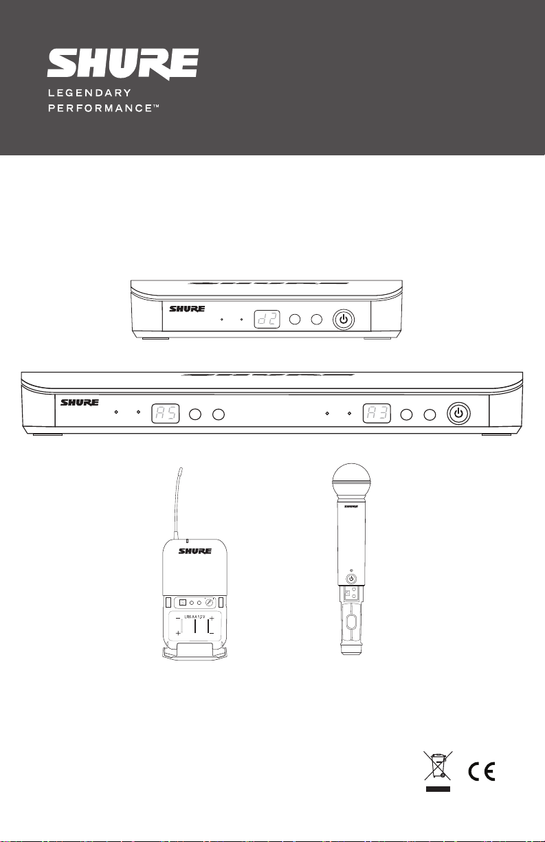
BLX Wireless System
ready
BLX4
audio
group
(A-Y)
channel
power
(0-9)
ready
BLX88
©2012 Shure Incorporated
27A16035 (Rev. 2)
audio
channel
group
(0-9)
(A-Y)
group
channel
(A-Y)
(0-9)
ready
audio
group
-10 dB
channel
group
(A-Y)
channel
power
(0-9)
Page 2

Page 3
Page 4

Page 5
BLX
System Components
Note: Your system comes with a combination of the following components.
• BLX1 Bodypack Transmitter
• BLX2 Handheld Transmitter (choice of SM58,
BETA58A, or PG58)
• BLX4 Wireless Receiver
• BLX88 Dual Wireless Receiver
• PS21 Power Supply
Features
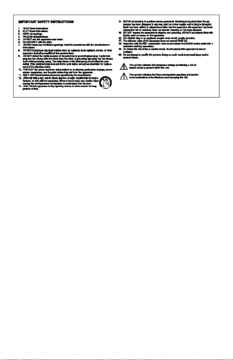
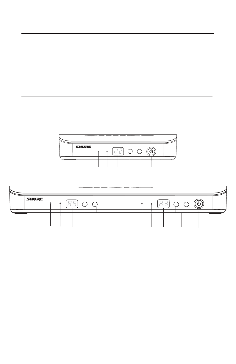
Front Panel
BLX4
BLX4
audio
• Lavalier microphone (choice of PG185, WL185 or
WL93)
• Headworn microphone (choice of PG30 or
WH30-TQG)
• Instrument microphone (BETA98H)
• Guitar cable (WA302)
power
channel
ready
group
(0-9)
(A-Y)
BLX88
BLX88
① audio LED
Indicates strength of incoming audio signal: green for
normal and red for overload.
② Ready LED Icon
Green light indicates system is ready for use and
receiving transmitter signal.
③ LED Display
Displays group and channel setting.
①
① ②
ready
audio
③
②
channel
group
(0-9)
(A-Y)
④
③
④ group and channel Buttons
Scan: Push and release group button to scan for an
open group and channel.
Manual: Push and hold group button to find an open
group. Push and release channel button to find a
channel in the current group.
⑤ power Button
Turns power on or off.
④
①
⑤
ready
audio
②
③
group
(A-Y)
④
channel
power
(0-9)
⑤
1
Page 6

Back Panel
POWER
MIC OUT
INSTRUMENT OUT
12-18 V
160 mA
BLX4
②
①
MIC OUT
INSTRUMENT OUT
④
②
① AC Adapter Jack
② Adapter Cord Tie-Off
③ XLR microphone output jack MIC out
④ 6.35 mm (1/4") instrument level output jack
instrument out
BLX1
① LED Indicator
Displays power and battery status (see table).
② power Switch
Toggles power on or off.
③ Audio Gain Adjustment
Gain thumb wheel—located on the inside of
bodypack door.
④ 4-Pin Microphone Input Jack (TA4
connector)
⑤ group Button
Changes group setting.
⑥ channel Button
Changes channel setting.
⑦ LED Display
Displays group and channel setting.
⑧ Antenna
⑨ Battery Compartment
⑥
③
④
12-18 V
160 mA
POWER
①
Note: XLR and 1/4" connectors can be used simultaneously. Refer to the output information in Specifications.
MIC OUT
③ ③
INSTRUMENT OUT
④
BLX1
⑧
⑦
⑤
group
channel
(A-Y)
(0-9)
③
⑨
①
BLX88
②
④
BLX2
BLX2
① LED Indicator
Displays power and battery status (see table).
② power Button
Push to turn power on or off.
③ group Button
Changes group setting.
④ channel Button
Changes channel and gain setting.
⑤ LED Display
Displays group and channel setting.
⑥ Identification Cap
2
⑦ Battery Compartment
②
⑤
⑦
①
-10 dB
⑥
group
③
channel
④
Page 7

Transmitter LED Indicators
channel
channel
channel
LED Indicator Status
Green Ready
Rapidly Flashing Amber Controls locked
Solid Red Battery power low (1 hour remaining*)
Flashing Red and shuts off Batteries dead (change batteries to power on transmitter)
*For alkaline batteries only. For rechargeable batteries, solid red means the batteries are dead.
Single System Setup
Before you begin, turn off all transmitters and turn on any equipment
(other microphones or personal monitoring systems) that could cause
interference during the performance.
1. Press and release the group button on the receiver.
The receiver scans for the clearest group and proceeds to channel
scan.
Note: If you want to stop the scan, push the group or channel
button.
2. Turn on transmitter and change the group and channel to match the
receiver (See Manually Setting Group and Channel).
Once the receiver is set up, perform an audio check on the
microphone.
Manually Setting Group and Channel
Receiver Setup
Group (letter)
1. Hold the group button on the receiver until
the display begins to flash.
2. While the display is flashing, press the
group button again to advance to the next
group.
Note: Only the group setting will be displayed during the manual setup.
3. Once the desired group is reached, release
the group button. Then the receiver will automatically perform a channel scan.
Channel (number)
If channel needs to be changed, follow the
same procedure using the channel button
instead of the group button.
group
group
group
group
group channel
channel
channel
channel
3
Page 8

Transmitter Setup
Transmitter group and channel must be manually set to match the receiver.
Group (letter)
1. Press and release the group button on the transmitter to activate the display. Press the group button again and the
display flashes.
2. While the display is flashing, press the group button again to advance to the desired group setting.
Channel (number)
If channel needs to be changed, follow the same procedure using the channel button instead of the group button.
Note: When the group and channel correctly match the receiver, the ready LED on receiver illuminates.
Multiple System Setup
Up to 12 systems can operate simultaneously (band and RF environment dependent).
Important: Set up each system one-at-a-time. Once a receiver and transmitter is tuned to the same group and channel,
leave the transmitter powered on. Otherwise, scans from the other receivers will not detect that channel as occupied. For
the BLX88, be sure to setup both transmitters before progressing to the next receiver.
Turn on any other equipment that could cause interference during the performance so it will be detected during the group
and channel scans in the following steps.
Before you begin system set up, turn all receivers ON and all transmitters OFF.
For the first receiver:
1. Perform a group scan.
This finds the group with the most clear channels.
Note: For the BLX88, the group scan sets up both receivers at the same time.
2. Turn on the first transmitter and change the group and channel to match receiver.
3. Leave the transmitter on and continue with the additional systems.
For each additional receiver:
1. Use manual setup to change the receiver to match the group setting of the first receiver. Recall that each time the
group setting is changed, a channel scan is automatically done.
2. Turn on the transmitter and change the group and channel to match the receiver.
3. Leave the transmitter on and continue to the next system.
4. Once all receivers are set up, perform an audio check on all microphones.
Locking and Unlocking Controls
Lock system controls to prevent accidental setting changes or power off.
Transmitter
Turn the transmitter on. Hold the group button, then
press the channel button for approximately 2 seconds.
The LED indicator rapidly flashes amber when locked and
green when unlocked.
4
Receiver
Turn the receiver on. Simultaneously press the group
and channel button to lock or unlock. The display flashes
rapidly.
When locked, the LED display flashes rapidly if any key
is pressed.
The BLX88 can be locked from either side for both sides.
Page 9

Wireless Tips to Improve System Performance
13 mm
(.5 in.)
If you encounter wireless interference or dropouts, try the following suggestions:
• Replace the transmitter batteries
• Choose a different frequency channel
• Reposition the antennas so there is nothing obstructing a line of sight to the transmitter (including the audience)
• Avoid placing transmitter and receiver where metal or other dense materials may be present
• Move the receiver to the top of the equipment rack
• Remove nearby sources of wireless interference, such as cell phones, two-way radios, computers, media players, and
digital signal processors
• Keep transmitters more than two meters (6 feet) apart
• Keep the transmitter and receiver more than 5 meters (16 feet) apart
• Keep them away from large metal objects
• During sound check, mark trouble spots and ask presenters or performers to avoid those areas
Getting Good Sound
Correct Microphone Placement
• Hold the microphone within 12 inches from the sound
source. For a warmer sound with increased bass
presence, move the microphone closer.
• Do not cover grille with hand.
Wearing the Headworn Microphone
• Position the headworn microhpone 13 mm (1/2 in.)
from the corner of your mouth.
• Position lavalier and headworn microphones so that
clothing, jewelry, or other items do not bump or rub
against the microphone.
Adjusting Gain
Monitor the audio LED indicator on the receiver front panel when setting the transmitter gain.
• Green: normal levels
• Red: excessive sound levels (overload).
BLX1
Use the thumb wheel on the inside of the bodypack bat-
terydoortoadjustthegainup(+)ordown(−)untildesired
level is reached. For instruments, turn gain to minimum
setting. For lavaliers, increase the gain as desired. The
audio LEDs on the receiver should illuminate when you
speak into the microphone or play your instrument. The
red LED should only illuminate infrequently when you
speak loudly or play your instrument loudly.
group
channel
(A-Y)
(0-9)
BLX2
The BLX2 features two gain level settings, default and
attenuated (-10 dB). The default setting is used for most
situations. If the receiver audio LED flickers red often, set
the microphone to attenuated. Use the channel button to
change the gain setting.
1. Hold down the channel button for 5 seconds.
A dot appears on the lower right-hand corner of the
LEDdisplay,whichindicates−10dBgainsettinghas
been activated.
2. To change the gain back to default, hold the channel
button again for 5 seconds, or until the dot disappears.
-10 dB
group
5 s
channel
5
Page 10

Batteries
Expected life for AA batteries is up to 14 hours (total
battery life varies depending upon battery type and
manufacturer).
When the LED indicator turns red, it signifies "low battery"
with approximately 60 minutes of remaining battery life.
For alkaline batteries only. For rechargeable batteries,
solid red means the batteries are dead.
To remove batteries from the handheld transmitter, push
them out through the opening in the microphone battery
compartment.
WARNING: Danger of explosion if battery
incorrectly replaced. Operate only with Shure
compatible batteries.
WARNING: Battery packs shall not be exposed
to excessive heat such as sunshine, fire, or
the like.
Wearing the Bodypack
Transmitter
Clip the transmitter to a belt or slide a guitar strap through
the transmitter clip as shown.
For best results, the belt should be pressed against the
base of the clip.
Power Off
Hold down the power button to power off the BLX2 or
BLX4/88. To power off the BLX1, slide the power toggle
switch to OFF.
Removing and Installing
Identification Caps
The BLX2 is equipped with a black identification cap from
the factory (dual vocal systems comes with a black and
gray cap).
To remove: Remove battery cover. Squeeze sides and
pull off cap.
To install: Make sure the tab matches the slot on the bottom of the handheld and click into place. Replace battery
cover.
An optional Identification Cap Kit containing 9 colored
caps is available (see Optional Accessories).
6
Page 11

Troubleshooting
Issue Indicator Status Solution
No sound or faint sound Receiver ready LED on • Verify all sound system connections or adjust
Receiver ready LED off • Turn on transmitter
gain as needed (see Adjusting Gain)
• Verify that the receiver is connected to mixer/
amplifier
• Make sure the batteries are installed correctly
• Perform transmitter setup (see Single System
Setup)
• Insert fresh batteries
Receiver LED screen off • Make sure AC adapter is securely plugged into
Transmitter indicator LED flashing red
Audio artifacts or dropouts Ready LED flickering or off • Change receiver and transmitter to a different
Distortion Audio LED on receiver indi-
Sound level variations
when switching to different
sources
Receiver/transmitter won't
turn off
*System must be set up within recommended range and receiver kept away from metallic surfaces.
cates overload (red)
N/A Adjust transmitter gain as necessary (see Adjusting
LED/display flashing rapidly See Locking and Unlocking Controls.
electrical outlet.
• Make sure receiver is powered on.
Replace transmitter batteries (see Changing
Batteries).
group and/or channel.
• Identify nearby sources of RF interference, and
shutdown or remove source.
• Replace transmitter batteries.
• Ensure that receiver and transmitter are
positioned within system parameters
System must be set up within recommended
range and receiver kept away from metallic
surfaces.
• Transmitter must be used in line of sight from
receiver for optimal sound
Reduce transmitter gain (see Adjusting Gain).
Gain).
7
Page 12

BLX
BLX2
Working Range
Audio Frequency
Response
Total Harmonic
Distortion
Ref. ±33 kHz deviation with 1 kHz tone
Dynamic Range
Operating
Temperature
Polarity
91 m (300 ft) Line of Sight
Note: Actual range depends
on RF signal absorption, reflection and interference.
50 to 15,000 Hz
Note: Dependent on microphone type
0.5%, typical
100 dBA-weighted, typical
-18°C (0°F) to 57°C (135°F)
Note: Battery characteristics
may limit this range.
Positive pressure on microphone diaphragm (or
positive voltage applied to
tip of WA302 phone plug)
produces positive voltage on
pin 2 (with respect to pin 3 of
low-impedance output) and
the tip of the high impedance
1/4-inch output.
BLX1
Audio Input Level gain position
max:
min (0
dB):
8
Gain Adjustment
Range
Input Impedance
RF Transmitter
Output
Dimensions
Weight
Housing
Power
Requirements
Battery Life
26 dB
1MΩ
10 mW, typical
varies by region
110 mm x 64 mm x 21 mm
(H x W x D)
75 g (2.6 oz.), without
batteries
Molded ABS
2 LR6 AA batteries, 1.5 V,
alkaline
up to 14 hours (alkaline)
-16 dBV
maximum
+10 dBV
maximum
Audio Input Level gain position
0dB:
-23 dBV
maximum
-10 dBV
maximum
Gain Adjustment
Range
RF Transmitter
Output
Dimensions
Weight
Housing
Power
Requirements
Battery Life
-10dB:
10 dB
10 mW, typical
varies by region
224 mm X 53 mm dia. (8 7/8
X 2 1/8 in.)
218 g (7.7 oz.) (without
batteries)
Molded ABS
2 LR6 AA batteries, 1.5 V,
alkaline
up to 14 hours (alkaline)
BLX4 & BLX88
Output Impedance XLR con-
Audio Output Level
Ref. ±33 kHz deviation
with 1 kHz tone
RF Sensitivity
Image Rejection
Dimensions BLX4:
Weight BLX4:
Housing
Power Requirements
nector:
6.35 mm
connec-
XLR con-
nector:
6.35 mm
connec-
-105 dBm for 12 dB SINAD,
typical
>50 dB, typical
BLX88:
BLX88:
Molded ABS
12–15 V DC @ 160 mA
(BLX88, 320 mA), supplied
by external power supply
(tip positive)
(1/4")
tor:
(1/4")
tor:
200Ω
50Ω
–27 dBV
(into100kΩ
load)
–13 dBV
(into100kΩ
load)
188 mm X
103 mm X
40 mm (H x
W x D)
388 mm X
116 mm X
40 mm (H x
W x D)
241 g (8.5
oz.)
429 g (15.1
oz.)
Page 13

Certifications
BLX1, BLX2, BLX4, BLX88
This Class B digital apparatus complies with Canadian
ICES-003. Cet appareil numérique de la classe B est conforme à la norme NMB-003 du Canada.
Meets requirements of the following standards: EN 300
422 Parts 1 and 2, EN 301 489 Parts 1 and 9, EN60065.
Meets essential requirements of the following European
Directives:
• R&TTE Directive 99/5/EC
• WEEE Directive 2002/96/EC, as amended by 2008/34/
EC
• RoHS Directive 2002/95/EC, as amended by 2008/35/
EC
Note: Please follow your regional recycling scheme for
batteries and electronic waste
BLX4, BLX88
Approved under the Declaration of Conformity (DoC) provision of FCC Part 15.
Certified by IC in Canada under RSS-123 and RSS-102.
IC: 616A-BLX4A, 616A-BLX4B, 616A-BLX4C,
616A-BLX4D, 616A-BLX88A, 616A-BLX88B,
616A-BLX88C, 616A-BLX88D
BLX1, BLX2
Certified under FCC Part 74.
Certified by IC in Canada under RSS-123 and RSS-102.
FCC ID: DD4BLX1A, DD4BLX1B, DD4BLX1C,
DD4BLX1D; DD4BLX2A, DD4BLX2B, DD4BLX2C,
DD4BLX2D. IC: 616A-BLX1A, 616A-BLX1B,
616A-BLX1C, 616A-BLX1D; 616A-BLX2A, 616A-BLX2B,
616A-BLX2C, 616A-BLX2D
This device complies with Industry Canada licence-exempt
RSS standard(s). Operation of this device is subject to the
following two conditions: (1) this device may not cause
interference, and (2) this device must accept any interference, including interference that may cause undesired
operation of the device.
Le présent appareil est conforme aux CNR d'Industrie
Canada applicables aux appareils radio exempts de
licence. L'exploitation est autorisée aux deux conditions
suivantes : (1) l'appareil ne doit pas produire de brouillage,
et (2) l'utilisateur de l'appareil doit accepter tout brouillage
radioélectrique subi, même si le brouillage est susceptible
d'en compromettre le fonctionnement.
The CE Declaration of Conformity can be obtained from
Shure Incorporated or any of its European representatives.
For contact information please visit www.shure.com
The CE Declaration of Conformity can be obtained from:
www.shure.com/europe/compliance
Authorized European representative:
Shure Europe GmbH
Headquarters Europe, Middle East & Africa
Department: EMEA Approval
Jakob-Dieffenbacher-Str. 12
75031 Eppingen, Germany
Phone: 49-7262-92 49 0
Fax: 49-7262-92 49 11 4
Email: EMEAsupport@shure.de
LICENSING INFORMATION
Licensing: A ministerial license to operate this equipment
may be required in certain areas. Consult your national
authority for possible requirements. Changes or modifications not expressly approved by Shure Incorporated could
void your authority to operate the equipment. Licensing
of Shure wireless microphone equipment is the user’s
responsibility, and licensability depends on the user’s classification and application, and on the selected frequency.
Shure strongly urges the user to contact the appropriate
telecommunications authority concerning proper licensing,
and before choosing and ordering frequencies.
Note: EMC conformance testing is based on the use of
supplied and recommended cable types. The use of other
cable types may degrade EMC performance.
Changes or modifications not expressly approved by
the manufacturer could void the user’s authority to
operate the equipment.
Information to the user
This equipment has been tested and found to comply with
the limits for a Class B digital device, pursuant to Part 15
of the FCC Rules. These limits are designed to provide
reasonable protection against harmful interference in a
residential installation. This equipment generates uses and
can radiate radio frequency energy and, if not installed
and used in accordance with the instructions, may cause
harmful interference to radio communications. However,
there is no guarantee that interference will not occur in a
particular installation. If this equipment does cause harmful
interference to radio or television reception, which can be
determined by turning the equipment off and on, the user
is encouraged to try to correct the interference by one or
more of the following measures:
• Reorient or relocate the receiving antenna.
• Increase the separation between the equipment and
the receiver.
• Connect the equipment to an outlet on a circuit
different from that to which the receiver is connected.
• Consult the dealer or an experienced radio/TV
technician for help.
9
Page 14

10
Page 15

www.shure.com
United States, Canada, Latin
America, Caribbean:
Shure Incorporated
5800 West Touhy Avenue
Niles, IL 60714-4608 USA
Phone: 847-600-2000
Fax: 847-600-1212 (USA)
Fax: 847-600-6446
Email: info@shure.com
©2012 Shure Incorporated
Europe, Middle East, Africa:
Shure Europe GmbH
Jakob-Dieffenbacher-Str. 12,
75031 Eppingen, Germany
Phone: 49-7262-92490
Fax: 49-7262-9249114
Email: info@shure.de
Asia, Pacific:
Shure Asia Limited
22/F, 625 King’s Road
North Point, Island East
Hong Kong
Phone: 852-2893-4290
Fax: 852-2893-4055
Email: info@shure.com.hk
 Loading...