

Page 1
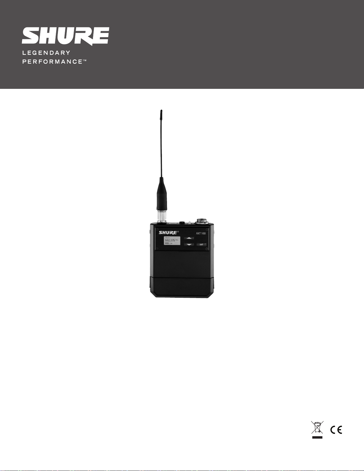
AXT100 Bodypack Transmitter
©2011 Shure Incorporated
27A15017 (Rev. 1)
Printed in USA
Page 2

Page 3
IMPORTANT SAFETY INSTRUCTIONS
READ these instructions.1.
KEEP these instructions.2.
HEED all warnings.3.
FOLLOW all instructions.4.
DO NOT use this apparatus near water.5.
CLEAN ONLY with dry cloth.6.
DO NOT block any ventilation openings. Install in accordance with 7.
the manufacturer’s instructions.
DO NOT install near any heat sources such as radiators, heat 8.
registers, stoves, or other apparatus (including ampliers) that
produce heat.
DO NOT defeat the safety purpose of the polarized or grounding-9.
type plug. A polarized plug has two blades with one wider than the
other. A grounding type plug has two blades and a third grounding
prong. The wider blade or the third prong are provided for your
safety. If the provided plug does not t into your outlet, consult an
electrician for replacement of the obsolete outlet.
PROTECT the power cord from being walked on or pinched, 10.
particularly at plugs, convenience receptacles, and the point where
they exit from the apparatus.
ONLY USE attachments/accessories specied by the 11.
manufacturer.
12.
USE only with a cart, stand, tripod, bracket, or table speci-
ed by the manufacturer, or sold with the apparatus. When
a cart is used, use caution when moving the cart/apparatus
combination to avoid injury from tip-over.
UNPLUG this apparatus during lightning storms or when unused 13.
for long periods of time.
REFER all servicing to qualied service personnel. Servicing is 14.
required when the apparatus has been damaged in any way, such
as power supply cord or plug is damaged, liquid has been spilled
or objects have fallen into the apparatus, the apparatus has been
exposed to rain or moisture, does not operate normally, or has
been dropped.
DO NOT expose the apparatus to dripping and splashing. DO 15.
NOT put objects lled with liquids, such as vases, on the apparatus.
The MAINS plug or an appliance coupler shall remain readily oper-16.
able.
The airborne noise of the Apparatus does not exceed 70dB (A).17.
Apparatus with CLASS I construction shall be connected to a 18.
MAINS socket outlet with a protective earthing connection.
To reduce the risk of re or electric shock, do not expose this ap-19.
paratus to rain or moisture.
Do not attempt to modify this product. Doing so could result in 20.
personal injury and/or product failure.
This symbol indicates that dangerous voltage constituting a
risk of electric shock is present within this unit.
This symbol indicates that there are important operating and
maintenance instructions in the literature accompanying this
unit.
WARNING: No user-serviceable parts inside. Refer all servicing to qualified service personnel.
WARNING: This product contains a chemical known to the State of California to cause cancer and birth defects or other reproductive harm.
WARNING
• Battery packs may explode or release toxic materials. Risk of fire or burns. Do not open, crush, modify,
disassemble, heat above 212°F (100°C), or incinerate
• Follow instructions from manufacturer
• Never put batteries in mouth. If swallowed, contact your physician or local poison control center
• Do not short circuit; may cause burns or catch fire
• Do not charge or use battery packs with other than specified Shure products
• Dispose of battery packs properly. Check with local vendor for proper disposal of used battery packs
Page 4

Page 5

AXT100 Axient Bodypack Transmitter
The AXT100 transmitter delivers superior audio performance in a compact, lightweight package. Efficient, ultra-linear RF performance maximizes
the number of channels on-air in crowded RF environments. Advanced power management provides extended, rechargeable battery life and highly
accurate status metering. ShowLink™ Remote Control enables comprehensive real-time remote control of all transmitter parameters, including
real-time frequency adjustments.
Features
• Ultra-linear RF performance places more channels on-air in crowded
RF environments
• IR Sync function automatically tunes transmitter to
the receiver frequency
• Comprehensive real-time remote control of all transmitter parameters
when a Linked transmitter is within range of a ShowLink Access Point
• Shure lithium-ion rechargeable battery delivers up to 8 hours of runtime
from a single charge
Transmitter Overview
① Infrared (IR) Port
Use for automated transmitter programming. Links transmitter
to AXT400 Receiver.
② Power Button
Hold for 1 second to turn the transmitter on. To power off, press
and hold for 2 seconds until the display reads “Powering Off “.
When editing, acts as an exit button to cancel changes and
return to a previous parameter or to the main menu screen.
③ Power Indicator LED
• Green = power on
• Red = audio input overload or low battery
④ Microphone Input
4-pin microphone input jack (LEMO version available)
⑤ Arrow Buttons
Use to scroll through menu screens and to change parameter values
⑥ Set Button
Enables parameter editing. After editing is complete, press to save
changes and return to the main menu screen
⑦ Shure Rechargeable Lithium-ion Battery
Delivers up to 8 hours of runtime from a single charge
⑧ LCD Display
View menu screens and settings. Momentarily press power button
to activate backlight
⑨ Dual-Band Flexible Antenna
Covers UHF tuning range and 2.4 GHz ShowLink signal
• Advanced control menu to adjust frequency and audio settings
from the transmitter
• 50 dB of adjustable gain for optimal audio quality
• Lockable user interface prevents accidental or inadvertent changes
to controls once settings are made
• Compatible with all Shure wireless microphones that have
a TA4F connector.
• LEMO connector version (AXT100LEMO3) available for use
with LEMO connector microphones
1
3
9
8
7
2
4
set
5
6
Included Components
Bodypack Rechargeable Lithium-ion Battery (2) AXT910
Dual-Band Flexible Antenna AXT642
Threaded TAF4 Adapter WA340
Transmitter Carrying Case WA610
Zipper Bag 26A13
Belt Clip 44A12547
Optional Accessories
Shure Lithium-ion Battery AXT910
Y-Cable for bodypack transmitter AXT652
LEMO Y-Cable for bodypack transmitters AXT652LEMO3
Dual-Band Flexible Antenna AXT642
Portable Bodypack Charging Station AXT903
3-AA Battery Sled for Axient bodypack transmitter AXT913
Instrument Cable WA302
Replacement belt clip 44A12547
Instrument cable with right angle 1/4” connector WA304
5
Page 6

6
Batteries
navigate
navigate control monitor
power
clip
push
1
2
push
enter
exit
audioRF
audioRF
sync
AXT400
A 470-698 MHz
Dual Wireless Receiver
A B
OL
A B
OL
set
The transmitter is powered by a Shure lithium-ion rechargeable battery.
Caution: Turn off the transmitter before changing batteries.
Note: Refer to your battery charger manual for charging instructions.
Press the release buttons to
remove the battery
Main Menu Screen
The main menu screen displays the following transmitter parameters:
Battery Runtime
Battery runtime varies according to the transmitter’s operating mode.
High power settings will reduce battery runtime.
Remaining battery runtime is shown on the display in hours and minutes
(accurate to within 15 minutes).
The times shown in the table represent a battery with a minimum of 5
charge cycles, fully charged, at 100% health.
RF Power Runtime
10 mW 8:00
100 mW 5:45
71
① Channel Name
• Linked : Displays Linked receiver
channel name
<U nl in ke d>
2
525.725 MHz
7: 45
3 4
}
|
5
6
Locking the Buttons
Lock the buttons of the transmitter to prevent
accidental or unauthorized parameter changes.
Press and hold the ▼ and ▲ buttons for 2
seconds to lock. Repeat to unlock.
• Unlinked : Not Linked to a receiver,
Channel Name reverts to <unlinked>
② Frequency
Tuned frequency of the transmitter
③ Battery Charge Indicator
5-segment icon indicates battery life
Hard Lock Switch
The Hard Lock switch located inside the battery
compartment provides an extra level of security
against accidental or unauthorized changes.
When the Hard Lock switch is engaged, the
Power, Set, and Arrow buttons cannot be used
to change the transmitters settings.
To access the Hard Lock switch, remove the
battery and set the switch to engage to lock the
controls or disengage unlock the controls.
Linking a Transmitter using IR Sync
The IR Sync function forms a Link and sets the frequency between the
transmitter and an AXT400 Receiver.
1. Align the IR Sync ports of the transmitter and the receiver. The red IR
Sync LED on the front panel of the receiver will illuminate to indicate
correct alignment.
2. Access the IR Sync function in the AXT400 Receiver menu: Tx > Sync
3. The receiver display indicates if the IR Sync is successful.
Check the transmitter alignment and select Retry if a failure occurs.
The transmitter device ID will be shown in the receiver Tx menu and
the receiver channel name and frequency will be shown on the
transmitter display, indicating a successful IR Sync.
④ Remaining Battery Life
Displays remaining battery life in
hours and minutes
⑤ ShowLink Icon
Indicates remote control of transmitter via
ShowLink is possible
⑥ Audio Meter
Indicates the audio signal level
⑦ Control Lock Icon
Displayed when buttons are locked
Power-on RF Mute
The transmitter can be powered-on in RF Mute
mode to prevent transmission of the audio
signal.
Press and hold the ▼ button during power-on
until the RF Muted message is displayed.
Using Two AXT100 Transmitters for
Frequency Diversity
Two AXT100 transmitters can be connected to two lavalier microphones
using an AXT652 “Y” cable to operate in Frequency Diversity mode
with an AXT400 Receiver.
1. Connect the “Y” cable to each transmitter and to the microphones.
2. From the AXT400 menu: Radio > Options > Diversity
3. Use the control wheel to set the mode to On-Bodypack.
4. Use the IR Sync function to Link a transmitter to each
channel of the receiver.
6
Page 7

Parameter Menus
To adjust transmitter settings, use the arrow buttons to access and edit the parameter menus.
Group (G) and Channel (Ch)
A group is a set compatible frequencies. A
single frequency within a group is a channel.
G: Change the group
Ch: Change the channel
Frequency
Manual frequency selection in
25 kHz increments.
Gain
Adjust the gain to set the input sensitivity level.
Gain range is -10 to +40 dB in 1 dB steps.
RF Mute
Disables or enables the RF carrier signal.
TX On: RF signal enabled
TX Off: RF signal disabled
Unlink
The Unlink command ends the Linking
relationship between a transmitter and
a receiver.
YES: Ends the Link between a transmitter and
a receiver.
NO: Preserves the Link between a transmitter
and a receiver.
ShowLink Test
Activates the ShowLink test 5-bar display
to measure the remote control range of a
ShowLink Access Point.
• 5 bars indicate the center of the
coverage area
• 1 bar indicates the outer boundary of the
coverage area
• If bars are not displayed, ShowLink control
is not available
Firmware
Displays the firmware version installed
in the transmitter
Device ID
The Device ID identifies the transmitter on a
network in WWB software or when Linked to a
receiver.
• ID length can be up to 8 characters
• Use arrow buttons to scroll through
characters
• Use set button to save and move to the next
character
AA Type
Sets the AA battery type (Alkaline, NiMH,
Lithium) to ensure accurate battery metering
when using the optional AXT913 3-AA battery
sled. The AA menu is only displayed when the
transmitter is powered by the sled.
RF PWR
From the main menu screen, press and hold
the set button and the ▼ button to edit the RF
power level.
Use lower power settings to conserve battery
life and to prevent RF overload at the receiver.
Note: A password is required in some regions.
PCB Serial Number
Use this menu to view the serial number of the
printed circuit board (PCB) installed in the unit.
1. From the main menu screen, press and
hold the ▼ and “set” buttons to enter the RF
Power screen.
2. Press the▲ button to access the serial
number.
3. Momentarily press the power button to
return to the home menu screen.
Note: When a transmitter is Unlinked, the
channel name will revert to Unlinked.
Troubleshooting
Input Overload
The Input Overload message indicates an excessive signal level at the
transmitter input. To prevent overload, reduce the gain setting.
No ShowLink Alert
This alert appears when frequency is edited on a linked transmitter that
is beyond the range of an active ShowLink access point. Choose OK to
unlink the transmitter and complete the frequency change, or Cancel to
return to the home screen.
Firmware Updates
Firmware is embedded software used to control features and the user interface. Periodically, new versions of firmware are available for download from
www.shure.com/wwb to incorporate additional features and enhancements. New versions of the firmware can be downloaded to AXT400 Receiver using
the Firmware Update Manager tool available in WWB6 software and installed on the transmitter using the infrared ports on the transmitter and receiver.
To access the AXT400 receiver firmware update menu: Tx > IR Presets > FW Update
Deeply Discharged Batteries
Deep discharge occurs when a battery is discharged to less than 3.0
volts. The battery chargers have a Recovery mode designed to restore
charge to a deeply discharged battery.
When the charger detects a deeply discharged battery, it automatically
enters Recovery mode which supplies reduced current to the battery for
up to 30 minutes.
If recovery is successful, the charger will exit Recovery mode and charge
the battery to capacity. If the battery cannot be recharged, charging stops
and the battery must be replaced.
7
Page 8

Specifications- AXT100 Bodypack Transmitter
RF Carrier Frequency
Range
Working Range Under typical conditions:
Audio Frequency
Response
RF Tuning Step Size
Modulation
45 kHz max. deviation
Dynamic Range
Total Harmonic
Distortion
45 kHz max. deviation
System Audio Polarity
470–814 MHz
Note: varies by region
Line of Sight, outdoors
for a single system:
Note: Actual range depends on RF signal absorption,
reflection and interference.
40 – 18 kHz (+1, -3 dB)
Note: Dependent on microphone type
25 kHz
FM, Audio Reference Companding with
pre- and de-emphasis
>113 dB, A-weighted (referenced at 0 dB
setting on transmitter)
<0.3%, A-weighted, typical
Positive pressure on microphone
diaphragm (or positive voltage applied
to tip of WA302 phone plug) produces
positive voltage on pin 2 (with respect to
pin 3 of low-impedance output) and the
tip of the high impedance 1/4-inch output.
AXT100
Gain Adjustment
Range
Battery Type
Battery Life
Dimensions
Weight
Housing
Operating
Temperature Range
Storage Temperature
Range
Audio Input
Connector
Configuration
Impedance
Maximum Input Level
1 kHz at 1% THD
-10 to +40 dB (in 1 dB steps)
Shure AXT910 (Rechargeable Li-Ion)
up to 8 hours (low power mode)
77 mm x 66 mm x 17 mm (3.0 in. x 2.6 in.
x 0.7 in.) H x W x D,
(with AXT910 battery)
146.6 g (5.2 oz.), with batteries
Cast aluminum
-18°C (0°F) to 63°C (145°F)
Note: Battery characteristics may limit this range.
-29°C (-20°F) to 74°C (165°F)
Note: Battery characteristics may limit this range.
4-Pin male mini connector (TA4M), 3-Pin
male mini connector (LEMO); See drawing for details
Unbalanced
1 MΩ
Gain
Setting:
−10 to +9 dB:
+10 to +19 dB:
+20 to +40 dB:
150 m
(500 ft)
500 m
(1600 ft)
12.5 dBu
−2.5 dBu
−7.5 dBu
RF Output
Connector
Antenna Type
Power
Impedance
SMA (UHF and ShowLink); Shell=Ground,
Center=Signal
AXT642 Bodypack Dual Band
Antenna(integrated helical and 1/4 wave)
See Frequency Range and
Ouput Power table
50 Ω
ShowLink
Network Type
Frequency Range
RF Output Power
IEEE 802.15.4
2.40 to 2.4835 GHz (16 Channels)
10 dBm (ERP)
Tables and Diagrams
Frequency Range and Transmitter Output Power
Band Frequency Range ( MHz) Power ( mW)
G1 470 to 530 10/100
G1E 470 to 530 10/50
H4 518 to 578 10/100
H4E 518 to 578 10/50
J5 578 to 638 10/100
J5E 578 to 638 10/50
K4E 606 to 666 10/50
L3 638 to 698 10/100
L3E 638 to 698 10/50
L3HK 638 to 698 10
M8 666 to 730 10/50
P8 710 to 790 10/50
P9 710 to 787 10/50
Q5 740 to 814 10/50
Q5HK 740 to 814 10
MA24 779 to 806 10
MJBX 806 to 810 10
8
Page 9

Lemo Connector
TA4M Connector
8.2K
100
100
47
8 V DC
Audio Input
Ground
Top view of bodypack
Audio Input
Bias Voltage
Ground
100
47
20K
100
8 V DC
Active Load
Audio Input
Ground
System Gain
System gain from transmitter input to Receiver XLR output (line) when transmitter gain = 0 dB
Transmitter
Receiver
gain setting = 0dB
AXT400
UR4
AXT100 Bodypack
gain = 0dB
+10dB gain +15dB gain +15dB gain +15dB gain +15dB gain
N/A N/A +18dB gain +18dB gain +18dB gain
AXT200 Handheld
gain = 0dB
Certifications
Meets essential requirements of European R&TTE Directive 99/5/EC, eligible to
bear the CE mark:
WEEE Directive 2002/95/EC as amended by 2008/34/EC.
RoHS Directive 2002/95/EC as amended by 2008/35/EC.
Meets requirements of EMC standards EN 300 328, EN 300 422 Parts 1 and 2, and
EN 301 489 Parts 1 and 9.
Certified under FCC Part 15 and FCC Part 74.
Certified in Canada by IC to RSS-123 and RSS-210.
This Class B digital apparatus complies with Canadian ICES-003.
Cet appareil numérique de la classe B est conforme à la norme NMB-003 du
Canada.
FCC ID: DD4AXT100. IC: 616A-AXT100.
Operation of this device is subject to the following two conditions: (1) this device
may not cause interference, and (2) this device must accept any interference,
including interference that may cause undesired operation of the device.
The CE Declaration of Conformity can be obtained from Shure Incorporated or any
of its European representatives. For contact information please visit www.shure.com
The CE Declaration of Conformity can be obtained from: www.shure.com/europe/
compliance
Authorized European representative:
Shure Europe GmbH
Headquarters Europe, Middle East & Africa
Department: EMEA Approval
Wannenacker Str. 28
D-74078 Heilbronn, Germany
Phone: +49 7131 72 14 0
Fax: +49 7131 72 14 14
Email: EMEAsupport@shure.de
Licensing Information
Licensing: A ministerial licence to operate this equipment may be
required in certain areas. Consult your national authority for possible
requirements.
Changes or modification not expressly approved by Shure Incorporated
could void your authority to operate the equipment. Licensing of
Shure wireless microphone equipment is the user’s responsibility, and
licensability depends on the user’s classification and application, and
on the selected frequency. Shure strongly urges the user to contact the
appropriate telecommunications authority concerning proper licensing,
and before choosing and ordering frequencies.
Information to the user
This equipment has been tested and found to comply with the limits for a Class
B digital device, pursuant to Part 15 of the FCC Rules. These limits are designed
to provide reasonable protection against harmful interference in a residential
installation. This equipment generates uses and can radiate radio frequency energy
and, if not installed and used in accordance with the instructions, may cause
harmful interference to radio communications. However, there is no guarantee that
interference will not occur in a particular installation. If this equipment does cause
harmful interference to radio or television reception, which can be determined
by turning the equipment off and on, the user is encouraged to try to correct the
interference by one or more of the following measures:
• Reorient or relocate the receiving antenna.
• Increase the separation between the equipment and the receiver.
• Connect the equipment to an outlet on a circuit different from that to which the
• Consult the dealer or an experienced radio/TV technician for help.
Top view of bodypack
UR1 Bodypack
gain = 0dB
sens = 0dB
receiver is connected.
Ground
Bias Voltage
Audio Input
Active Load
UR1M Bodypack
gain = 0dB
sens = 0dB
UR2 Handheld
gain = 0dB
9
Page 10

Page 11

Page 12

www.shure.com
United States, Canada, Latin
America, Caribbean:
Shure Incorporated
5800 West Touhy Avenue
Niles, IL 60714-4608 USA
Phone: 847-600-2000
Fax: 847-600-1212 (USA)
Fax: 847-600-6446
Email: info@shure.com
©2011 Shure Incorporated
Europe, Middle East, Africa:
Shure Europe GmbH
Wannenäckestr. 28,
74078 Heilbronn, Germany
Phone: 49-7131-72140
Fax: 49-7131-721414
Email: info@shure.de
Asia, Pacific:
Shure Asia Limited
22/F, 625 King’s Road
North Point, Island East
Hong Kong
Phone: 852-2893-4290
Fax: 852-2893-4055
Email: info@shure.com.hk
 Loading...