

Page 1

9/20/17, 8*58 AMShure Publications | User Guides | ULX-D Dual and Quad Z16-20
Page 1 of 96http://pubs.shure.com/guide/ULXD-DQ/en-US
ULX-D Dual and Quad
Z16-20
ULX-D® Digital Wireless Microphone
System
IMPORTANT SAFETY
INSTRUCTIONS
1. READ these instructions.
2. KEEP these instructions.
3. HEED all warnings.
4. FOLLOW all instructions.
5. DO NOT use this apparatus near water.
6. CLEAN ONLY with dry cloth.
7. DO NOT block any ventilation openings. Allow
sufficient distances for adequate ventilation and
install in accordance with the manufacturer’s
instructions.
8. DO NOT install near any heat sources such as open
flames, radiators, heat registers, stoves, or other
apparatus (including amplifiers) that produce heat.
Do not place any open flame sources on the product.
9. DO NOT defeat the safety purpose of the polarized
or grounding type plug. A polarized plug has two
blades with one wider than the other. A grounding
type plug has two blades and a third grounding
Publications User Guides ULXD-DQ (English)
› ›
Download PDF
English
Table of Contents
IMPORTANT SAFETY
INSTRUCTIONS
Important Product
Information
Quickstart Instructions
General Description
Hardware Interface
Transmitter IR Presets
Batteries
Setting Receiver Gain
Scan and Sync
RF
Networking ULX-D Receivers
System Reset
Firmware
Connecting to an External
Control System
Page 2
9/20/17, 8*58 AMShure Publications | User Guides | ULX-D Dual and Quad Z16-20
Page 2 of 96http://pubs.shure.com/guide/ULXD-DQ/en-US
prong. The wider blade or the third prong are
provided for your safety. If the provided plug does
not fit into your outlet, consult an electrician for
replacement of the obsolete outlet.
10. PROTECT the power cord from being walked on or
pinched, particularly at plugs, convenience
receptacles, and the point where they exit from the
apparatus.
11. ONLY USE attachments/accessories specified by the
manufacturer.
12. USE only with a cart, stand, tripod, bracket, or table
specified by the manufacturer, or sold with the
apparatus. When a cart is used, use caution when
moving the cart/apparatus combination to avoid
injury from tip-over.
13. UNPLUG this apparatus during lightning storms or
when unused for long periods of time.
14. REFER all servicing to qualified service personnel.
Servicing is required when the apparatus has been
damaged in any way, such as power supply cord or
plug is damaged, liquid has been spilled or objects
have fallen into the apparatus, the apparatus has
Managing the ULXD Receiver
with Wireless Workbench 6
Troubleshooting
Certifications
Specifications
Accessories
Page 3
9/20/17, 8*58 AMShure Publications | User Guides | ULX-D Dual and Quad Z16-20
Page 3 of 96http://pubs.shure.com/guide/ULXD-DQ/en-US
been exposed to rain or moisture, does not operate
normally, or has been dropped.
15. DO NOT expose the apparatus to dripping and
splashing. DO NOT put objects filled with liquids,
such as vases, on the apparatus.
16. The MAINS plug or an appliance coupler shall remain
readily operable.
17. The airborne noise of the Apparatus does not exceed
70dB (A).
18. Apparatus with CLASS I construction shall be
connected to a MAINS socket outlet with a protective
earthing connection.
19. To reduce the risk of fire or electric shock, do not
expose this apparatus to rain or moisture.
20. Do not attempt to modify this product. Doing so
could result in personal injury and/or product failure.
21. Operate this product within its specified operating
temperature range.
Explanation of Symbols
Caution: risk of electric shock
Caution: risk of danger (See note.)
Direct current
Alternating current
On (Supply)
Equipment protected throughout by DOUBLE
INSULATION or REINFORCED INSULATION
Stand-by
Equipment should not be disposed of in the
Page 4

9/20/17, 8*58 AMShure Publications | User Guides | ULX-D Dual and Quad Z16-20
Page 4 of 96http://pubs.shure.com/guide/ULXD-DQ/en-US
normal waste stream
WARNING: Voltages in this equipment are hazardous to
life. No user-serviceable parts inside. Refer all servicing to
qualified service personnel. The safety certifications do
not apply when the operating voltage is changed from
the factory setting.
Important Product Information
LICENSING INFORMATION
Licensing: A ministerial license to operate this equipment
may be required in certain areas. Consult your national
authority for possible requirements. Changes or
modifications not expressly approved by Shure
Incorporated could void your authority to operate the
equipment. Licensing of Shure wireless microphone
equipment is the user’s responsibility, and licensability
depends on the user’s classification and application, and
on the selected frequency. Shure strongly urges the user
to contact the appropriate telecommunications authority
concerning proper licensing, and before choosing and
ordering frequencies.
Information to the user
This equipment has been tested and found to comply
with the limits for a Class B digital device, pursuant to Part
15 of the FCC Rules. These limits are designed to provide
reasonable protection against harmful interference in a
residential installation. This equipment generates uses
and can radiate radio frequency energy and, if not
installed and used in accordance with the instructions,
Page 5

9/20/17, 8*58 AMShure Publications | User Guides | ULX-D Dual and Quad Z16-20
Page 5 of 96http://pubs.shure.com/guide/ULXD-DQ/en-US
may cause harmful interference to radio communications.
However, there is no guarantee that interference will not
occur in a particular installation. If this equipment does
cause harmful interference to radio or television
reception, which can be determined by turning the
equipment off and on, the user is encouraged to try to
correct the interference by one or more of the following
measures:
Reorient or relocate the receiving antenna.
Increase the separation between the equipment and
the receiver.
Connect the equipment to an outlet on a circuit
different from that to which the receiver is connected.
Consult the dealer or an experienced radio/TV
technician for help.
Note: EMC conformance testing is based on the use of supplied
and recommended cable types. The use of other cable types may
degrade EMC performance.
Please follow your regional recycling scheme for batteries,
packaging, and electronic waste.
This device complies with Industry Canada licenceexempt RSS standard(s). Operation of this device is
subject to the following two conditions: (1) this device
may not cause interference, and (2) this device must
accept any interference, including interference that may
cause undesired operation of the device.
Le présent appareil est conforme aux CNR d'Industrie
Canada applicables aux appareils radio exempts de
licence. L'exploitation est autorisée aux deux conditions
suivantes : (1) l'appareil ne doit pas produire de
brouillage, et (2) l'utilisateur de l'appareil doit accepter
tout brouillage radioélectrique subi, même si le brouillage
est susceptible d'en compromettre le fonctionnement.
WARNING: Danger of explosion if incorrect battery
Page 6

9/20/17, 8*58 AMShure Publications | User Guides | ULX-D Dual and Quad Z16-20
Page 6 of 96http://pubs.shure.com/guide/ULXD-DQ/en-US
replaced. Operate only with AA batteries.
Note: Use only with the included power supply or a Shureapproved equivalent.
WARNING
Battery packs may explode or release toxic materials.
Risk of fire or burns. Do not open, crush, modify,
disassemble, heat above 140°F (60°C), or incinerate.
Follow instructions from manufacturer
Only use Shure charger to recharge Shure
rechargeable batteries
WARNING: Danger of explosion if battery incorrectly
replaced. Replace only with same or equivalent type.
Never put batteries in mouth. If swallowed, contact
your physician or local poison control center
Do not short circuit; may cause burns or catch fire
Do not charge or use battery packs other than Shure
rechargeable batteries
Dispose of battery packs properly. Check with local
vendor for proper disposal of used battery packs.
Batteries (battery pack or batteries installed) shall not
be exposed to excessive heat such as sunshine, fire
or the like
Australia Warning for Wireless
This device operates under an ACMA class licence and
must comply with all the conditions of that licence
including operating frequencies. Before 31 December
2014, this device will comply if it is operated in the 520820 MHz frequency band. WARNING: After 31 December
2014, in order to comply, this device must not be
operated in the 694-820 MHz band.
WARNING: This product contains a chemical known to the State
of California to cause cancer and birth defects or other
Page 7

9/20/17, 8*58 AMShure Publications | User Guides | ULX-D Dual and Quad Z16-20
Page 7 of 96http://pubs.shure.com/guide/ULXD-DQ/en-US
reproductive harm.
Quickstart Instructions
General Description
Shure ULX-D™ Digital Wireless offers uncompromising 24bit audio quality and RF performance, with intelligent,
encryption-enabled hardware, flexible receiver options,
and advanced rechargeability options for professional
sound reinforcement.
Page 8

9/20/17, 8*58 AMShure Publications | User Guides | ULX-D Dual and Quad Z16-20
Page 8 of 96http://pubs.shure.com/guide/ULXD-DQ/en-US
A breakthrough in wireless audio quality, Shure digital
processing enables ULX-D to deliver the purest
reproduction of source material ever available in a
wireless system, with a wide selection of trusted Shure
microphones to choose from. Extended 20 Hz – 20 kHz
frequency range and flat response captures every detail
with clarity, presence, and incredibly accurate low end
and transient response. With greater than 120 dB, ULX-D
delivers wide dynamic range for excellent signal-to-noise
performance. Optimized for any input source, ULX-D
eliminates the need for transmitter gain adjustments.
ULX-D sets a new and unprecedented standard for
spectral efficiency and signal stability. The
intermodulation performance of ULX-D is an incredible
advancement in wireless performance, enabling a
dramatic increase in the number of simultaneous active
transmitters on one TV channel. Rock-solid RF signal with
zero audio artifacts extends over the entire range. For
applications where secure wireless transmission is
required, ULX-D offers Advanced Encryption Standard
(AES) 256-bit encrypted signal for unbreakable privacy.
For scalability and modular flexibility, ULX-D receivers
come in single, dual, and even quad channel versions.
The dual and quad channel receivers offer conveniences
such as RF cascade, internal power supply, bodypack
frequency diversity, audio output channel summing, and
Dante™ digital networking for multi-channel audio over
Ethernet. All receivers offer High-Density mode for
applications where high channel counts are needed,
greatly increasing the amount of simultaneous channels
possible over one frequency band.
Advanced Lithium-ion rechargeability provides extended
transmitter battery life over alkaline batteries, battery life
metering in hours and minutes accurate to within 15
Page 9
9/20/17, 8*58 AMShure Publications | User Guides | ULX-D Dual and Quad Z16-20
Page 9 of 96http://pubs.shure.com/guide/ULXD-DQ/en-US
minutes, and detailed tracking of battery health status.
Generations ahead of any other available system in its
class, ULX-D brings a new level of performance to
professional sound reinforcement.
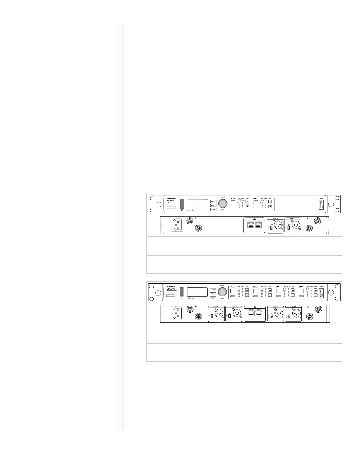
Dual and Quad Receiver Models
The ULXD4 receiver is available in dual channel and quad
channel models. Both models share the same feature set
and functionality, but differ in the number of channels
available and the number of audio outputs.
The descriptions and procedures in this guide are
applicable to either the dual or the quad receiver.
ULXD4D Dual Receiver
Supports 2 channels of wireless audio.
ULXD4Q Quad Receiver
Supports 4 channels of wireless audio.
Hardware Interface
Receiver
Page 10
9/20/17, 8*58 AMShure Publications | User Guides | ULX-D Dual and Quad Z16-20
Page 10 of 96http://pubs.shure.com/guide/ULXD-DQ/en-US
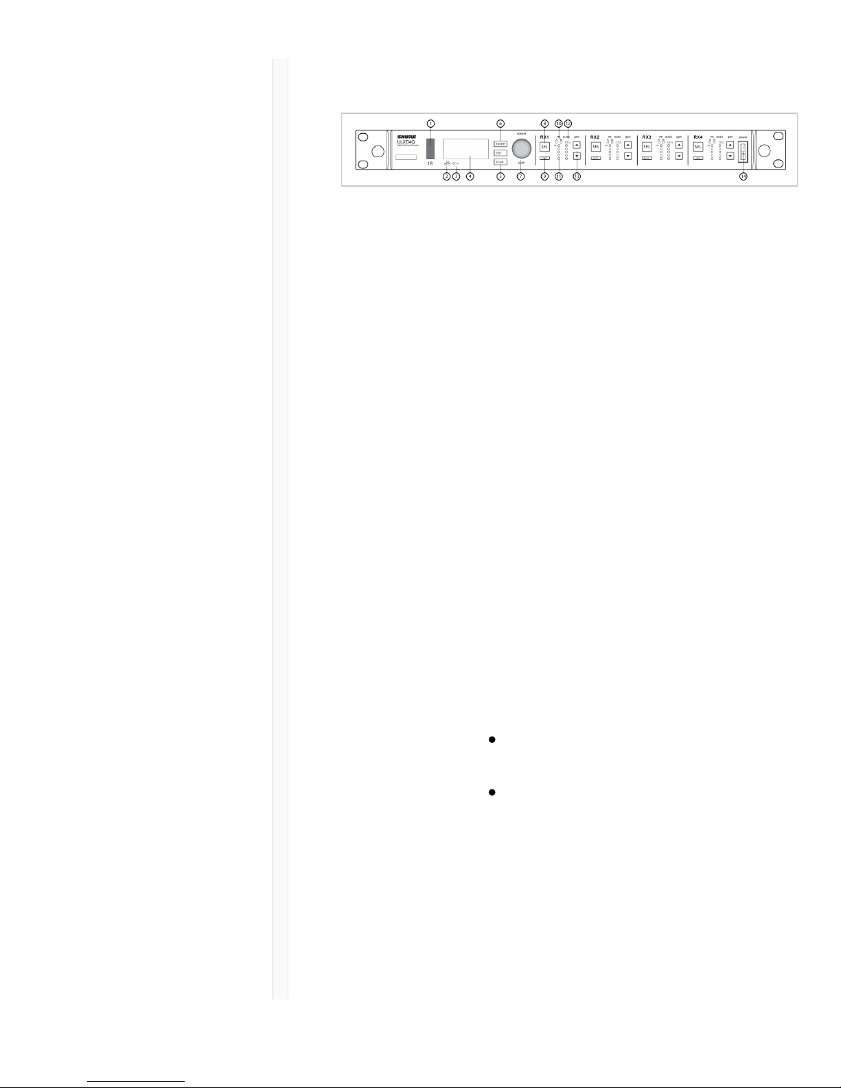
Front Panel
ɠ Infrared
(IR) Sync
Window
Sends IR signal to the transmitter for
sync.
ɡ Network
Icon
Illuminates when the receiver is
connected with other Shure devices on
the network. IP Address must be valid
to enable networked control.
ɢ
Encryption
Icon
Illuminates when AES-256 encryption is
activated.
ɣ LCD Panel Displays settings and parameters.
ɤ Scan
Button
Press to find the best channel or group.
ɥ Menu
Navigation
Buttons
Use to navigate and select parameter
menus.
ɦ Control
Wheel
Push to select a channel or menu
item
Turn to scroll through menu items
or to edit a parameter value
ɧ Channel
Select Button
Press to select a channel.
ɨ Sync
Button
Press the sync button while the receiver
and transmitter IR windows are aligned
to transfer settings from the receiver to
Page 11

9/20/17, 8*58 AMShure Publications | User Guides | ULX-D Dual and Quad Z16-20
Page 11 of 96http://pubs.shure.com/guide/ULXD-DQ/en-US
the transmitter.
ɩ RF
Diversity
LEDs
Indicate antenna status:
Blue = normal RF signal between
the receiver and transmitter
Red = interference detected
Off = No RF connection between
the receiver and transmitter
Note: the receiver will not output audio
unless one blue LED is illuminated.
ꋷ RF Signal
Strength
LEDs
Indicate the RF signal strength from the
transmitter:
Amber = Normal (-90 to -70 dBm)
Red = Overload (greater than -25
dBm)
ꋸ Audio
LEDs
Indicate average and peak audio levels:
LED Audio Signal
Level
Description
Red (6) -0.1 dBFS Overload/
limiter
Yellow (5) -6 dBFS Normal peaks
Yellow (4) -12 dBFS
Green (3) -20 dBFS Signal Present
Green (2) -30 dBFS
Green (1) -40 dBFS
Note: In Frequency Diversity mode,
simultaneous blinking of the red and yellow
audio LEDs indicates that diversity audio has
been routed to this channel.
ꋹ Gain
Buttons
Press the ▼ gain buttons on the front
of the receiver to incrementally adjust
gain from -18 to +42 dB.
Page 12
9/20/17, 8*58 AMShure Publications | User Guides | ULX-D Dual and Quad Z16-20
Page 12 of 96http://pubs.shure.com/guide/ULXD-DQ/en-US
ꋺ Power
Switch
Powers the unit on or off.
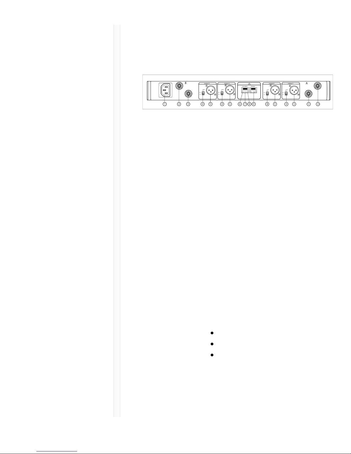
Back Panel
ɠ AC Power
Input
IEC Connector, 100 - 240 V AC.
ɡ RF Antenna
Diversity Input
Jack (2)
For antenna A and antenna B.
ɢ RF Cascade
Jack (2)
Passes the RF signal from Antenna A
and Antenna B to one additional
receiver.
ɣ Mic/Line
Switch (one
per channel)
Applies a 30 dB pad in mic position.
ɤ Balanced
XLR Audio
Output (one
per channel)
Connect to a mic or line level input.
ɥ Network
Status LED
(Green)
One per network port.
Off = no link
On = network link
Flashing = network link active
ɦ
Ethernet/Dante
Network
Secondary Port
Connect to an Ethernet network to
enable remote device control via
WWB6 software. Also carries Dante
digital audio and control signals for
Page 13
9/20/17, 8*58 AMShure Publications | User Guides | ULX-D Dual and Quad Z16-20
Page 13 of 96http://pubs.shure.com/guide/ULXD-DQ/en-US
audio distribution, monitoring, and
recording - see Dante Network topic.
ɧ Network
Speed LED
(Amber)
One per network port.
Off = 10/100 Mbps
On = 1 Gbps
ɨ
Ethernet/Dante
Network
Primary Port
Connect to an Ethernet network to
enable remote device control via
WWB6 software. Also carries Dante
digital audio and control signals for
audio distribution, monitoring, and
recording - see Dante Network topic.
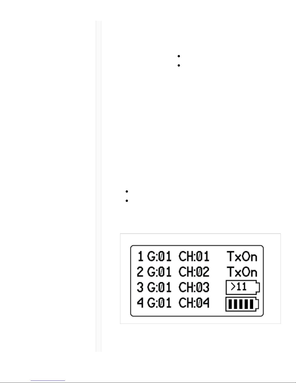
Receiver Home Screen
The home screen displays the following information for
each receiver channel:
Group and Channel
Transmitter Status: NoTx or TxOn, battery
icon/remaining battery life
Press the SEL button to access a channel menu screen.
Page 14

9/20/17, 8*58 AMShure Publications | User Guides | ULX-D Dual and Quad Z16-20
Page 14 of 96http://pubs.shure.com/guide/ULXD-DQ/en-US
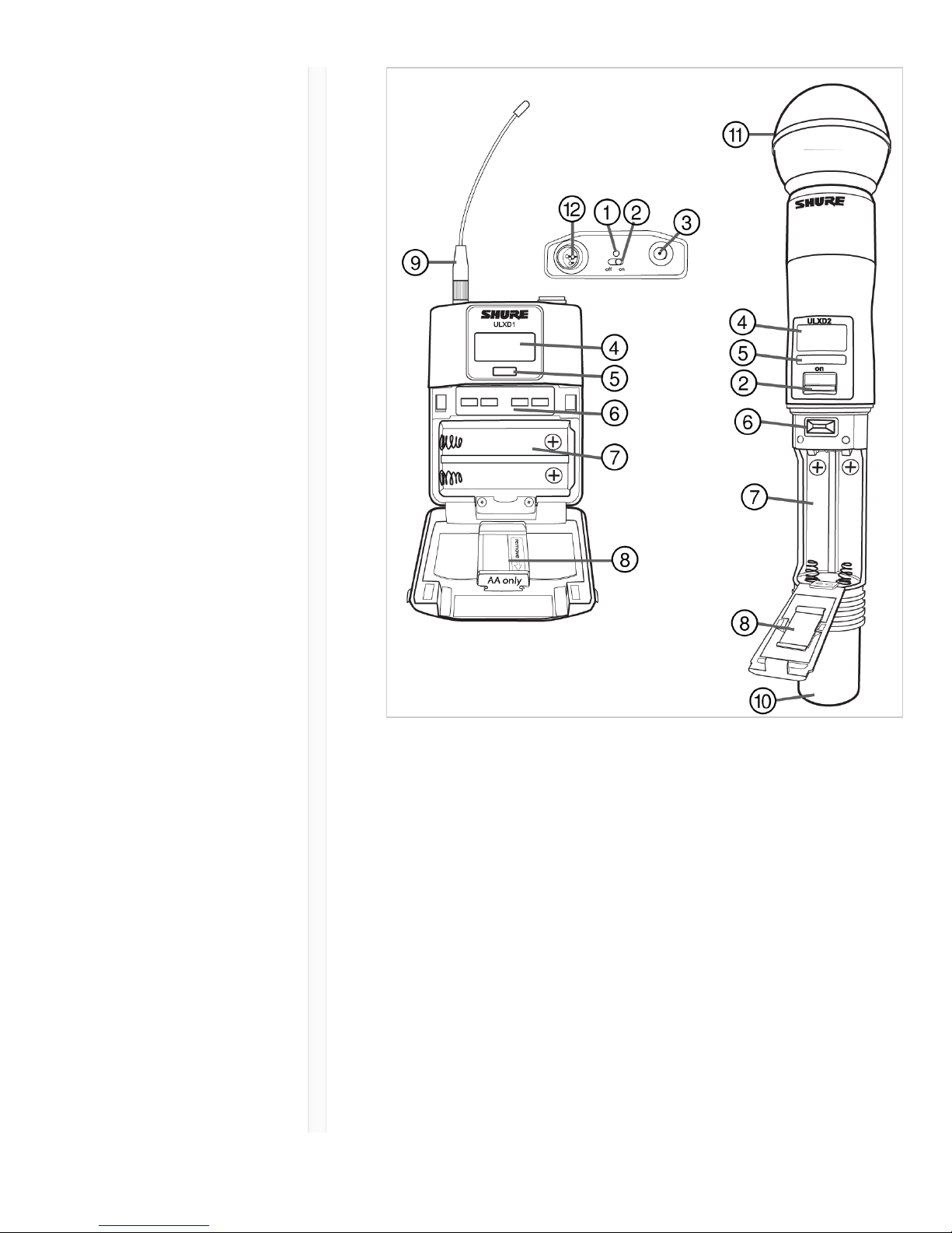
Transmitters
ɠ Power LED Green = unit is powered on
Red = low battery or battery error
(see Troubleshooting)
Amber = power switch is disabled
ɡ On/Off
Switch
Powers the unit on or off.
ɢ SMA
Connector
Connection point for RF antenna.
ɣ LCD
Display:
View menu screens and settings. Press
any control button to activate the
backlight.
ɤ Infrared
(IR) Port
Align with the receiver IR port during
an IR Sync for automated transmitter
programming.
ɥ Menu
Navigation
Buttons
Use to navigate through parameter
menus and change values.
exit Acts as a 'back' button to return
to previous menus or
parameters without confirming
a value change
enter Enters menu screens and
confirms parameter changes
▼ Use to scroll through menu
screens and to change
parameter values
ɦ Battery
Compartment
Requires Shure SB900 rechargeable
battery or 2 AA batteries.
ɧ AA Battery Handheld: rotate and store in the
Page 15

9/20/17, 8*58 AMShure Publications | User Guides | ULX-D Dual and Quad Z16-20
Page 15 of 96http://pubs.shure.com/guide/ULXD-DQ/en-US
Adapter battery compartment to use a
Shure SB900 battery
Bodypack: remove to
accommodate a Shure SB900
battery
ɨ Bodypack
Antenna
For RF signal transmission.
ɩ Integrated
Antenna
For RF signal transmission.
ꋷ
Microphone
Cartridge
See Optional Accessories for a list of
compatible cartridges.
ꋸ TA4M /
LEMO Input
Jack
Connects to a microphone or
instrument cable.
Page 16
9/20/17, 8*58 AMShure Publications | User Guides | ULX-D Dual and Quad Z16-20
Page 16 of 96http://pubs.shure.com/guide/ULXD-DQ/en-US
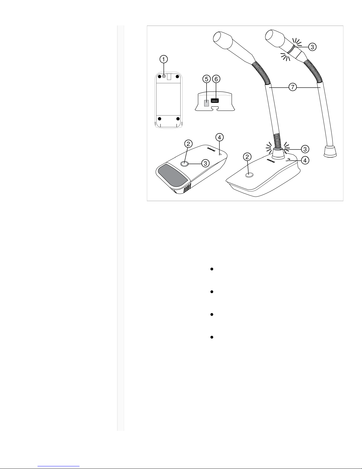
Boundary and Gooseneck Base
Transmitters
Page 17
9/20/17, 8*58 AMShure Publications | User Guides | ULX-D Dual and Quad Z16-20
Page 17 of 96http://pubs.shure.com/guide/ULXD-DQ/en-US
ɠ Power
Button
Press to power on; press and hold to
power off.
ɡ
Mute/Active
Button
Four settings are available for the
mute/active button:
Toggle: Press to switch between
active and mute states
Push-to-Mute: Hold button to mute
microphone
Push-to-Talk: Hold button to
activate microphone
Disabled: Button functionality off
ɢ Mute LED Indicates whether microphone is active
or muted. The following settings are
available:
Active Muted
Green* Red*
Red Off
Page 18

9/20/17, 8*58 AMShure Publications | User Guides | ULX-D Dual and Quad Z16-20
Page 18 of 96http://pubs.shure.com/guide/ULXD-DQ/en-US
Red Flashing
red
*MX400R series gooseneck
microphones (red LED) do not offer this
setting.
ɣ LowBattery LED
Off = More than 30 minutes of
battery life remain
On (red) = Less than 30 minutes of
battery life remain
On (green) = Microphone docked
on charging station
On (amber) = Battery is missing or
is not inserted correctly
ɤ Infrared
(IR) Port
Align with receiver IR port to send
settings to transmitter.
ɥ Charge
Connector
Connects to networked chargers and
USB power supply.
ɦ
Gooseneck
Microphone
ULXD8 base fits 5", 10", and 15"
Microflex series microphones, available
in single or dualflex and with bi-color or
red-only LEDs.
Advanced Transmitter Features
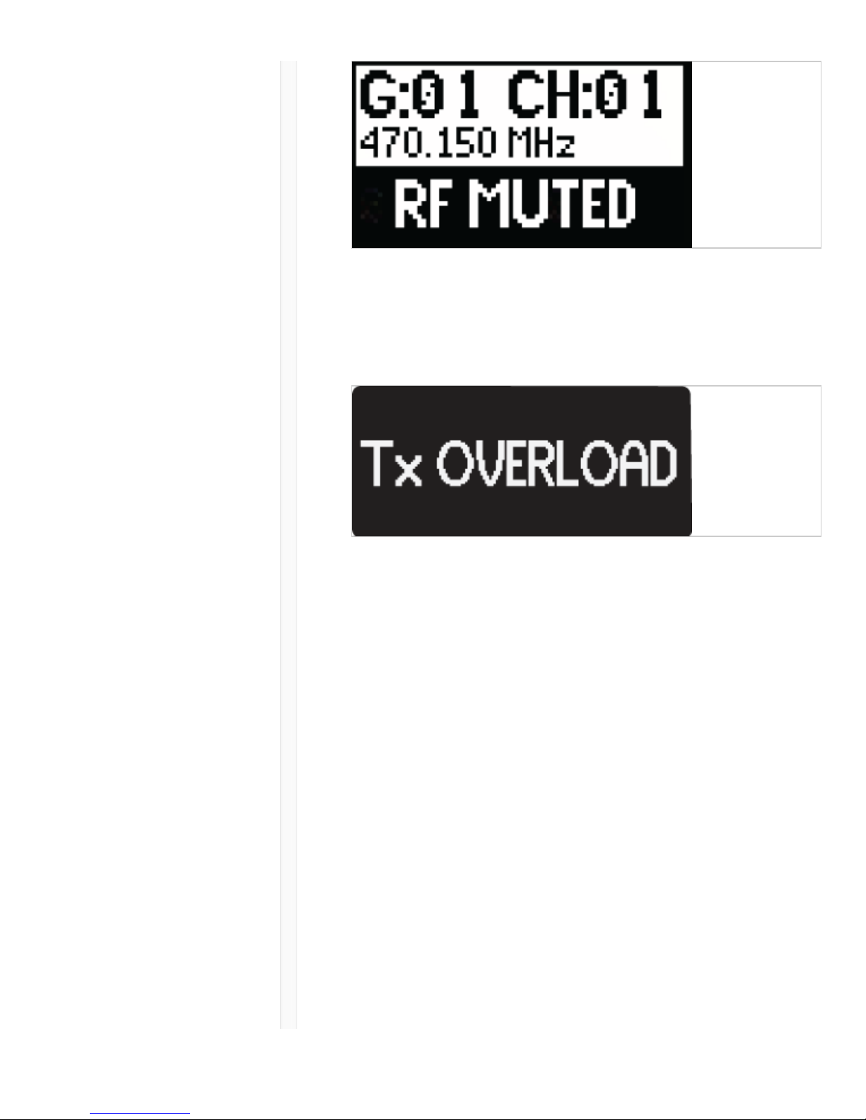
RF MUTE
Use this to turn on a transmitter without interfering with
the RF spectrum.
Press and hold the exit button during power-on until RF
MUTED is displayed. To un-mute, restart the transmitter.
Page 19
9/20/17, 8*58 AMShure Publications | User Guides | ULX-D Dual and Quad Z16-20
Page 19 of 96http://pubs.shure.com/guide/ULXD-DQ/en-US
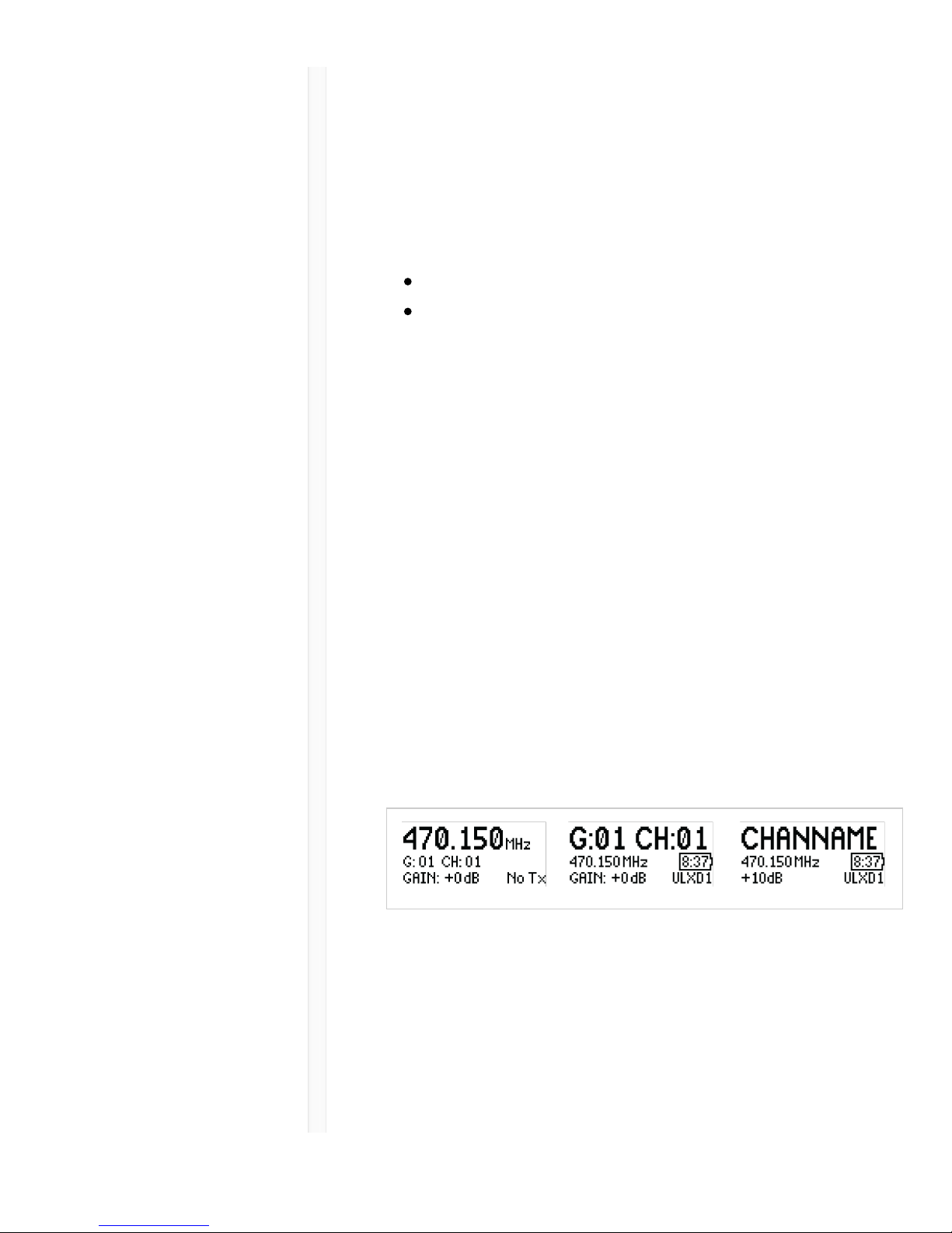
Transmitter Input Clip
The following warning displays on the receiver LCD panel
when the transmitter input is clipped:
To correct, set MIC.OFFSET to 0 dB and if necessary,
attenuate the signal source.
If the source cannot be attenuated while using a
bodypack transmitter, select INPUT PAD from the main
menu to attenuate the input signal by 12 dB.
MIC.OFFSET
MIC.OFFSET compensates for signal level differences
between transmitters that share the same receiver
channel.
Set the offset gain on a low signal level transmitter to
match a louder transmitter: UTILITY > MIC.OFFSET
Note: For normal gain adjustments, use the receiver gain buttons.
Transmitter Audio Mute Mode
Mute Mode reconfigures the transmitter power switch to
Page 20

9/20/17, 8*58 AMShure Publications | User Guides | ULX-D Dual and Quad Z16-20
Page 20 of 96http://pubs.shure.com/guide/ULXD-DQ/en-US
act a mute switch for the audio. Using the switch, the
audio can be easily turned on or muted by presenters,
sports referees, or anyone who periodically needs to
speak. When the audio is muted, the transmitter RF signal
remains on and ready at all times.
Note: Mute Mode can be selected as an IR PRESET option.
To set a transmitter to Mute Mode:
1. From the transmitter menu: UTILITY > MUTE MODE
2. Use the arrows to select ON or OFF.
3. Press enter to save.
Tip: The transmitter LED turns red when audio is muted
and turns green when audio is enabled. The display of the
transmitter will show AUDIO MUTED and the receiver
display will show Tx Muted.
Note: Mute Mode must be set to OFF in order to use the power
switch to turn off the transmitter.
Locking Controls and Settings
Use the LOCK feature to prevent accidental or
unauthorized changes to the hardware.
Receiver
Menu path: DEVICE UTILITIES > LOCK
Use the control wheel to select and lock any of the
following receiver functions.
MENU: All menu paths are inaccessible
GAIN: Gain adjustment is locked
POWER: Power switch is disabled
SCN/SYC: Cannot perform a Scan and Sync
Tip: To unlock, press the EXIT button, turn the control
wheel to select UNLOCKED, and then press ENTER to
Page 21
9/20/17, 8*58 AMShure Publications | User Guides | ULX-D Dual and Quad Z16-20
Page 21 of 96http://pubs.shure.com/guide/ULXD-DQ/en-US
save.
Transmitter
Menu path: UTILITY > LOCK
Use the transmitter controls to select and lock any of the
following transmitter functions.
MENU LOCK: All menu paths are inaccessible.
POWER LOCK: Power switch is disabled
Quick-Lock Option: To turn on the transmitter with its
power and menu navigation buttons locked, press and
hold the button during power-on until the locked
message is displayed.
Tip: To unlock the MENU LOCK, press the ENTER button 4 times
to pass through the following screens: UTILITY > LOCK > MENU
UNLOCK
To unlock the POWER LOCK, set the power switch to the
off position, then press and hold the button while
resetting the power switch to the on position.
Home Screen Display Options
Receiver
The HOME INFO menu provides options to change the
information shown on the receiver home screen:
DEVICE UTILITIES > HOME INFO
Use the control wheel to select one of the following
screen displays.
Page 22
9/20/17, 8*58 AMShure Publications | User Guides | ULX-D Dual and Quad Z16-20
Page 22 of 96http://pubs.shure.com/guide/ULXD-DQ/en-US
Transmitter
Home Screen: Press the ▼ arrows at the home menu to
display one of the following screens:
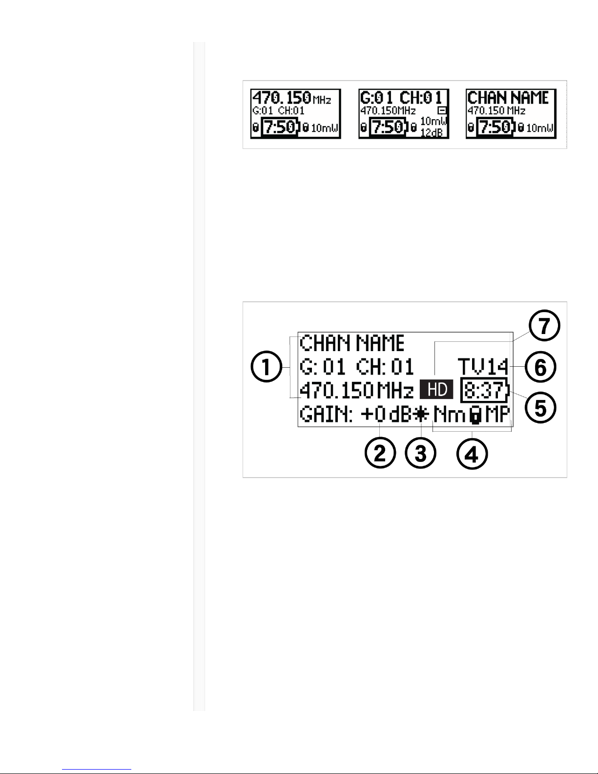
Menu Screens
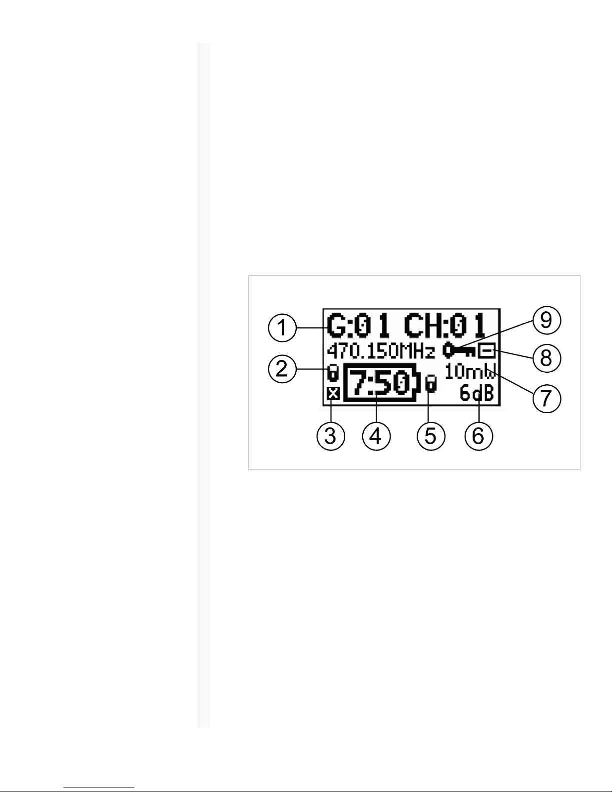
Receiver Channel
ɠ Receiver
Information
Use DEVICE UTILITIES > HOME INFO
to change the home screen display.
ɡ Gain
Setting
−18 to +42 dB, or Mute.
ɢ Mic.
Offset
Indicator
Indicates offset gain is added to the
transmitter.
ɣ
Transmitter
The following information cycles when a
transmitter is tuned to the receiver's
Page 23
9/20/17, 8*58 AMShure Publications | User Guides | ULX-D Dual and Quad Z16-20
Page 23 of 96http://pubs.shure.com/guide/ULXD-DQ/en-US
Settings frequency:
Transmitter Type
Input Pad (Bodypack only)
RF Power Level
Transmitter Lock Status
Transmitter Mute Status
ɤ Battery
Runtime
Indicator
Shure SB900 battery: runtime is
displayed in minutes remaining.
AA batteries: runtime is displayed with a
5-bar indicator.
ɥ TV
Channel
Displays the TV channel that contains
the tuned frequency.
ɦ High
Density
Mode Icon
Displayed when High Density mode is
enabled.
Transmitter
Status
The following text or icons report
transmitter status to the receiver screen:
Display
Icon
Transmitter Status
Bodypack input is
attenuated 12 dB
Offset gain is added to the
transmitter
Lo 1 mW RF power level
Nm 10 mW RF power level
Hi 20 mW RF power level
M Menu is locked
Page 24
9/20/17, 8*58 AMShure Publications | User Guides | ULX-D Dual and Quad Z16-20
Page 24 of 96http://pubs.shure.com/guide/ULXD-DQ/en-US
P Power is locked
TxMuted Displayed when the
transmitter audio is set to off
using the MUTE MODE
feature
-No Tx- No RF connection between a
receiver and transmitter or
transmitter OFF
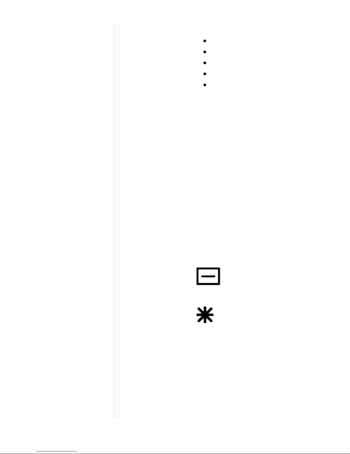
Transmitter
ɠ
Transmitter
Information
Scroll ▼ at the home screen to
change the display
ɡ Power
Lock
Indicator
Indicates power switch is disabled
ɢ
Transmitter
Audio Muted
Indicator
Displayed when the transmitter audio is
set to off using the MUTE MODE
feature.
Page 25

9/20/17, 8*58 AMShure Publications | User Guides | ULX-D Dual and Quad Z16-20
Page 25 of 96http://pubs.shure.com/guide/ULXD-DQ/en-US
ɣ Battery
Runtime
Indicator
Shure SB900 battery: runtime is
displayed in hours:minutes
remaining
AA Batteries: runtime is displayed
with a 5-bar indicator
ɤ Menu
Lock
Indicator
Indicates menu navigation buttons are
disabled
ɥ Mic.
Offset
Displays microphone offset gain value
ɦ RF Power Displays RF power setting
ɧ Bodypack
Input Pad
The input signal is attenuated 12 dB
ɨ
Encryption
Icon
Indicates encryption is enabled on the
receiver and has been transferred to the
transmitter from a sync
Adjusting Receiver Display Brightness and Contrast
Adjust BRIGHTNESS and CONTRAST settings to improve
visibility in challenging lighting environments.
1. From the receiver menu: DEVICE UTILITIES >
DISPLAY
2. Press the control wheel to select CONTRAST or
BRIGHTNESS.
3. Turn the control to adjust the selected parameter.
4. Press ENTER to save changes.
Editing Receiver Channel Name
To edit a receiver channel name, choose EDIT NAME from
the menu.
Turn the control wheel to edit a highlighted character
Page 26

9/20/17, 8*58 AMShure Publications | User Guides | ULX-D Dual and Quad Z16-20
Page 26 of 96http://pubs.shure.com/guide/ULXD-DQ/en-US
Press the control wheel to advance to the next
character
Press ENTER to save changes
Note: The channel name is transferred to a transmitter during a
sync.
Receiver Menu Descriptions
RADIO
Displays Group, Channel, Frequency, and TV information.
Use the control wheel to edit values
G: Group for the selected frequency
CH: Channel for the selected frequency
FREQUENCY Selected frequency (MHz)
TV: Displays the TV channel for the selected
frequency
AUDIO
GAIN Use the control wheel or gain buttons to
adjust the channel gain from -18 to 42
dB, in 1 dB increments.
MUTE Mutes the receiver audio output.
EDIT NAME
Use the control wheel to assign and edit the selected
receiver channel name.
IR PRESETS
BODYPACK / HANDHELD
BP PAD Sets the audio input attenuation
options: KEEP, 0, -12.
LOCK Sets the lock options: KEEP, Power,
Page 27

9/20/17, 8*58 AMShure Publications | User Guides | ULX-D Dual and Quad Z16-20
Page 27 of 96http://pubs.shure.com/guide/ULXD-DQ/en-US
Menu, All, None
RF POWER Sets the transmitter RF power level:
KEEP, 10mW=Nm, 1mW=Lo,
20mW=Hi.
BATT Sets the transmitter battery type to
ensure accurate metering: KEEP,
Alkaline, NiMH, Lithium
BP OFFSET Adjustable gain to compensate for
signal level difference between
transmitters: KEEP, 0 to 21 dB in 3 dB
increments
HH OFFSET Adjustable gain to compensate for
signal level difference between
transmitters: KEEP, 0 to 21 dB in 3 dB
increments
MUTE
MODE
Configures the transmitter power switch
to act as an audio mute switch.
Cust. Group Create Custom Groups of up to 6
frequencies and export to networked
receivers
GOOSENECK / BOUNDARY
HIGH PASS Attenuates frequencies below 150 Hz
by 12 dB per octave: KEEP, OFF, ON
RF POWER Sets the transmitter RF power level:
KEEP, 10mW=Nm, 1mW=Lo,
20mW=Hi
BATTERY Sets the transmitter battery type to
ensure accurate metering: KEEP,
Alkaline, NiMH, Lithium
BN OFFSET Adjustable gain to compensate for
signal level difference between
Page 28

9/20/17, 8*58 AMShure Publications | User Guides | ULX-D Dual and Quad Z16-20
Page 28 of 96http://pubs.shure.com/guide/ULXD-DQ/en-US
transmitters: KEEP, 0 to 21 dB in 3 dB
increments
GN OFFSET Adjustable gain to compensate for
signal level difference between
transmitters: KEEP, 0 to 21 dB in 3 dB
increments
POWER LOCK Locks the transmitter's power button:
KEEP, OFF, ON
Cust. Group Create Custom Groups of up to 6
frequencies and export to networked
receivers
INITIAL
STATE FROM
CHARGER
Choose the transmitter's state after it
is removed from a charger: KEEP,
Active, Muted, OFF
MUTE
BUTTON
BEHAVIOR
Sets the mute button behavior: KEEP,
Toggle, Push-to-Talk, Push-to-Mute,
Disabled
BN MUTE
LED
ACTIVE/MUTE
Sets the mute LED colors for active
and muted states: KEEP, Green/Red,
Red/OFF, Red/Flash-Red, OFF/OFF
GN MUTE
LED
ACTIVE/MUTE
Sets the mute LED colors for active
and muted states: KEEP, Green/Red,
Red/OFF, Red/Flash-Red, OFF/OFF
MUTE LED
LIGHT
BRIGHTNESS
Sets the mute LED brightness: KEEP,
Normal, Low
BATTERY INFO
HEALTH Percentage of charge capacity
compared to a new battery
CHARGE Percentage of charge capacity
Page 29

9/20/17, 8*58 AMShure Publications | User Guides | ULX-D Dual and Quad Z16-20
Page 29 of 96http://pubs.shure.com/guide/ULXD-DQ/en-US
CYCLES Number of charge cycles logged by the
battery
TEMP Battery temperature: °C/°F
DEVICE UTILITIES
FREQ
DIVERSITY
OFF (default)
1 + 2
3 + 4 (quad only)
1 + 2 / 3 + 4 (quad only)
AUDIO
SUMMING
OFF (default)
1 + 2
3 + 4 (quad only)
1 + 2 / 3 + 4 (quad only)
1 + 2 + 3 + 4 (quad only)
ENCRYPTION Set encryption: ON/OFF
ADVANCED
RF
HIGH DENSITY: ON/OFF
CUSTOM GROUPS:
SETUP/EXPORT/CLEAR
ANTENNA BIAS: ON/OFF
SWITCH BAND (Japan AB band
only)
LOCK MENU: LOCKED/UNLOCKED
GAIN: LOCKED/UNLOCKED
POWER: LOCKED/UNLOCKED
SCN/SYC: LOCKED/UNLOCKED
HOME INFO Select screen options for Home Menu.
DISPLAY CONTRAST
BRIGHTNESS:
LOW/MEDIUM/HIGH
Page 30

9/20/17, 8*58 AMShure Publications | User Guides | ULX-D Dual and Quad Z16-20
Page 30 of 96http://pubs.shure.com/guide/ULXD-DQ/en-US
NETWORK CONFIGURATION:
SWITCHED/REDUNDANT
AUDIO/SPLIT
SHURE CONTROL: DEVICE ID,
Network Mode, Set IP and Subnet
values for Ethernet network
DANTE: DANTE DEVICE ID,
AUDIO & CNTRL, REDUNDANT
AUDIO, Set IP, Subnet, Gateway
and Yamaha values for Dante
™
network
Note: Additional information can be
accessed from the selected networking
option.
TX FW
UPDATE
IR DOWNLOAD, Tx Firmware Version
SYSTEM
RESET
RESTORE: Default Settings,
Presets
SAVE: Create New Preset
DELETE: Delete Preset
VERSION Model
Band
S/N (serial number)
Ver
Mcu
FPGA
Boot
Transmitter IR Presets
Use the IR PRESETS receiver menu to quickly configure
transmitter settings from the receiver screen. When a sync
is performed between the receiver and transmitter, the IR
Page 31

9/20/17, 8*58 AMShure Publications | User Guides | ULX-D Dual and Quad Z16-20
Page 31 of 96http://pubs.shure.com/guide/ULXD-DQ/en-US
PRESETs automatically configure the transmitter. Each
parameter has the default value KEEP, which leaves that
setting unaffected by a sync.
Feature Setting
BP PAD +0 dB, -12 dB
LOCK Power, Menu, All, None
RF POWER 10mW=Nm (normal), 1mW=Lo
(low), 20mW=Hi (high)
BATT Alkaline, NiMH, Lithium
BP OFFSET 0 dB to +21 dB (in 3 dB
increments)
HH OFFSET 0 dB to +21 dB (in 3 dB
increments)
MUTE MODE OFF, ON
Cust. Group OFF, ON
Note: When Cust. Groups is set to on, it may take up to 30
seconds to complete an IR sync.
Creating a System Preset
System Presets allow a current receiver setup to be saved
and restored. Presets store all receiver settings to provide
a quick way to configure a receiver or switch between
several different setups. Up to 4 presets can be stored in
receiver memory.
To save the current receiver setup as a new preset:
DEVICE UTILITIES > SYSTEM RESET > SAVE > CREATE
NEW PRESET
Use the control wheel to name the preset, and then press
Enter to save.
To recall a saved preset: DEVICE UTILITIES > SYSTEM
Page 32

9/20/17, 8*58 AMShure Publications | User Guides | ULX-D Dual and Quad Z16-20
Page 32 of 96http://pubs.shure.com/guide/ULXD-DQ/en-US
RESET > RESTORE
Use the control wheel to select the preset name, and then
press Enter.
Batteries
The transmitter runs on two AA batteries or the Shure
SB900 rechargeable battery. Use the included AA battery
adapter when using batteries other than the Shure SB900.
Bodypack: Remove the adapter when using the Shure
SB900
Handheld: Rotate and store the adapter in battery door
when using Shure SB900
Battery Runtime Charts
A 5-segment icon on the receiver and transmitter menu
screens indicates battery charge.
For accurate battery runtime monitoring, set the
transmitter to the appropriate battery type: UTILITY >
BATTERY > SET.AA.TYPE .
The tables display the approximate hours and minutes
remaining (h:mm).
Alkaline
Page 33

9/20/17, 8*58 AMShure Publications | User Guides | ULX-D Dual and Quad Z16-20
Page 33 of 96http://pubs.shure.com/guide/ULXD-DQ/en-US
Battery Indicator RF Power Setting
10 mW 20 mW
>11:00
to 9:35
5:45 to 5:15
9:35 to
6:00
5:15 to 4:00
6:00 to
2:30
4:00 to 2:00
2:30 to
1:00
2:00 to 0:50
1:00 to
0:20
0:50 to 0:10
0:20 to
0:00
0:10 to 0:00
NiMH
Battery Indicator RF Power Setting
10 mW 20 mW
>13:00 to 11:10 9:00 to 7:40
11:10 to 7:00 7:40 to 5:15
7:00 to 2:50 5:15 to 2:05
2:50 to 1:25 2:05 to 1:00
1:25 to 0:20 1:00 to 0:15
0:20 to 0:00 0:15 to 0:00
Page 34

9/20/17, 8*58 AMShure Publications | User Guides | ULX-D Dual and Quad Z16-20
Page 34 of 96http://pubs.shure.com/guide/ULXD-DQ/en-US
Shure SB900 Rechargeable Battery
When using an SB900 rechargeable battery, the receiver
and transmitter home screens display the number of hours
and minutes remaining.
Detailed information for the SB900 is displayed in the
receiver BATTERY INFO menu and the transmitter menu:
UTILITY > BATTERY > BATT. STATS
HEALTH: Displays battery health as a percentage of the
charge capacity of a new battery.
CHARGE: Percentage of a full charge
CYCLES: Number of times the battery has been charged
TEMP: Battery temperature in Celsius and Fahrenheit
Note: For additional rechargeable battery information, visit
www.shure.com.
Shure SB900 Runtime
1 mW 10 mW 20 mW
>11 hours >11 hours >7 hour
Important Tips for Care and Storage of
Page 35

9/20/17, 8*58 AMShure Publications | User Guides | ULX-D Dual and Quad Z16-20
Page 35 of 96http://pubs.shure.com/guide/ULXD-DQ/en-US
Shure Rechargeable Batteries
Proper care and storage of Shure batteries results in
reliable performance and ensures a long lifetime.
Always store batteries and transmitters at room
temperature
Ideally, batteries should be charged to approximately
40% of capacity for long-term storage
During storage, check batteries every 6 months and
recharge to 40% of capacity as needed
Installing the Battery Contact Cover
Install the included battery contact cover (65A15947) on
the handheld transmitter to prevent light reflection in
broadcast and performance situations.
1. Align the cover as shown.
2. Slide the cover over the battery contacts until it is
flush with the transmitter body.
Note: Slide the cover off before inserting the transmitter in the
battery charger.
Page 36

9/20/17, 8*58 AMShure Publications | User Guides | ULX-D Dual and Quad Z16-20
Page 36 of 96http://pubs.shure.com/guide/ULXD-DQ/en-US
Setting Receiver Gain
The receiver gain control sets the audio signal level for
the entire receiver and transmitter system. Changes to the
gain settings occur in realtime allowing for adjustments
during live performances. When adjusting the gain,
monitor the audio meter levels to prevent signal
overloads.
Receiver Gain Controls
The gain can be adjusted by using the gain ▼ buttons
or by entering the AUDIO menu and using the control
wheel.
Tip: To quickly adjust the gain, press and hold a gain
button to enable accelerated scrolling.
Reading the Audio Meter
The audio meter displays yellow, green, and red LEDs to
indicate the audio signal level. Audio peaks illuminate the
LEDs for 2 seconds, while the RMS signal is displayed in
realtime.
When setting up the receiver, adjust the gain so that the
average signal LED levels are solid green and occasionally
Page 37

9/20/17, 8*58 AMShure Publications | User Guides | ULX-D Dual and Quad Z16-20
Page 37 of 96http://pubs.shure.com/guide/ULXD-DQ/en-US
yellow, with only the highest peaks causing the red LED to
illuminate.
Tip: If a vocalist is overloading a bodypack transmitter, try lowing
the receiver gain. If additional attenuation is needed, use the
transmitter menu to set the INPUT PAD to -12dB.
Note: Illumination of the red OL (overload) LED indicates the
internal limiter is engaged to prevent digital clipping.
Muting a Receiver Channel Audio Output
The audio output of each receiver channel can be
independently muted to prevent audio from passing.
Mute status is indicated by Rx MUTED message
appearing on the receiver display in place of the gain
value.
Note: Receiver gain is disabled for muted channels to prevent
unexpected changes in audio levels.
To set a receiver channel output to mute:
1. AUDIO > MUTE
2. Use the control wheel to select ON or OFF.
3. Press ENTER to save.
To unmute the receiver output:
Simultaneously press the ▼ buttons or select OFF from
the MUTE menu option.
Tip: Audio mute can be enabled remotely from Wireless
Workbench or from an external controller.
Important! A power cycle will reset the receiver and
unmute the audio output.
Transmitter Input Clip
The following warning displays on the receiver LCD panel
when the transmitter input is clipped:
Page 38

9/20/17, 8*58 AMShure Publications | User Guides | ULX-D Dual and Quad Z16-20
Page 38 of 96http://pubs.shure.com/guide/ULXD-DQ/en-US
To correct, attenuate the signal source. If the source
cannot be attenuated while using a bodypack transmitter,
select INPUT PAD from the main menu to attenuate the
input signal 12 dB.
Audio Summing
Audio summing allows the dual and quad receivers to
function as a 2 or 4 channel mixer, respectively. All XLR
outputs of the selected channels provide the summed
audio. For example, when 1 + 2 is selected (see diagram),
the XLR outputs of channels 1 and 2 supply the summed
audio of the two channels.
Choosing an Audio Summing Mode
The following Audio Summing mode options are
available:
Page 39

9/20/17, 8*58 AMShure Publications | User Guides | ULX-D Dual and Quad Z16-20
Page 39 of 96http://pubs.shure.com/guide/ULXD-DQ/en-US
Page 40

9/20/17, 8*58 AMShure Publications | User Guides | ULX-D Dual and Quad Z16-20
Page 40 of 96http://pubs.shure.com/guide/ULXD-DQ/en-US
To select an Audio Summing mode:
1. Menu: DEVICE UTILITIES > AUDIO SUMMING
2. Use the control wheel to select an option, and then
press Enter.
Note: When set to OFF, Audio Summing is disabled.
Adjusting Gain for Summed Outputs
Use the gain controls for each channel to create the
overall mix balance. The front panel LEDs indicate the
audio level for each channel. If an overload occurs, the
red LEDs will illuminate indicating that the internal limiter
is active and the display will show an overload message.
To correct, adjust the overall gain balance.
Receiver Output Level
The following table describes the typical total system gain
from the audio input to the receiver outputs:
Receiver Output Gain
Output Jack System Gain (gain control = 0dB)
XLR (line setting) +24 dB
Page 41

9/20/17, 8*58 AMShure Publications | User Guides | ULX-D Dual and Quad Z16-20
Page 41 of 96http://pubs.shure.com/guide/ULXD-DQ/en-US
XLR (mic setting) -6 dB*
*This setting matches a typical wired SM58 audio signal level.
Scan and Sync
Use this procedure to tune a receiver and transmitter to
the best open channel.
Important! Before you begin:
Turn off all transmitters for the systems you are setting up.
(This prevents them from interfering with the frequency
scan.)
Turn on the following potential sources of interference so
they are operating as they would be during the
presentation or performance (the scan will detect and
avoid any interference they generate).
Other wireless systems or devices
Computers
CD players
Large LED panels
Effects processors
1. Press the SEL button to select a receiver channel.
2. Perform a group scan on the receiver: SCAN >
GROUP SCAN .
3. Press SCAN to start the scan. SCANNING appears on
the LCD during the scan.
4. After the scan completes, the receiver displays the
group with the most available frequencies. Press the
flashing ENTER button to deploy frequencies to each
receiver channel.
5. Power on the ULXD transmitter.
6. Press the sync button on the receiver.
7. Align the IR windows until the receiver IR port
illuminates red.
Page 42

9/20/17, 8*58 AMShure Publications | User Guides | ULX-D Dual and Quad Z16-20
Page 42 of 96http://pubs.shure.com/guide/ULXD-DQ/en-US
Note: When complete, SYNC SUCCESS! appears. The transmitter
and receiver are now tuned to the same frequency.
Multiple System Setup
A setup using networked receivers is the fastest and
easiest way to distribute the best open channel to each
system. See Networking ULX-D Receivers for networking
Page 43

9/20/17, 8*58 AMShure Publications | User Guides | ULX-D Dual and Quad Z16-20
Page 43 of 96http://pubs.shure.com/guide/ULXD-DQ/en-US
details.
Note: Networked receivers must all be within the same frequency
band.
Networked Receivers
1. Turn on all receivers.
2. Conduct a group scan on the first receiver to find
available frequencies in each group: SCAN > GROUP
SCAN .
3. Press ENTER to accept the group number and
automatically assign the next best channel to each
receiver on the network. The receiver LEDs will flash
when a frequency has been assigned.
4. Turn on a transmitter and sync to the receiver.
Important! Leave the transmitter on and repeat this
step for each additional system.
Non-networked Receivers
1. Turn on all receivers.
2. Conduct a group scan on the first receiver to find
available frequencies in each group: SCAN > SCAN >
GROUP SCAN > SCAN
3. When the scan is complete, use the control wheel to
scroll through each group. Press ENTER to select a
group that has enough available frequencies for all
channels in the system.
4. Sync a transmitter to each receiver channel.
Important! Leave all transmitters on use the following steps to set
up additional receiver channels:
1. Set each additional receiver channel to the same
group as the first receiver: RADIO > G:
2. Conduct a channel scan to find available frequencies
within the group: SCAN > SCAN > CHANNEL SCAN
> SCAN
3. When the scan is complete, press ENTER to assign
Page 44

9/20/17, 8*58 AMShure Publications | User Guides | ULX-D Dual and Quad Z16-20
Page 44 of 96http://pubs.shure.com/guide/ULXD-DQ/en-US
frequencies to each receiver channel.
4. Sync a transmitter to each receiver channel.
Manual Frequency Selection
To manually adjust group, channel, or frequency:
1. Press SEL to choose a receiver channel and navigate
to the RADIO menu.
2. Use the control wheel to adjust the group, channel,
or frequency.
3. Press ENTER to save changes.
RF
Transmitter RF Power
Reference the following table for setting RF Power:
RF Power Setting System Range Application
1 mW 33 m (100 ft.) For increased channel
reuse at close
distances
10 mW 100 m (330 ft.) Typical setups
20 mW >100 m (330 ft.) For hostile RF
environments or longdistance applications
Note: Using the 20 mW setting decreases the transmitter battery
runtime and reduces the number of compatible systems.
Interference Detection
Page 45

9/20/17, 8*58 AMShure Publications | User Guides | ULX-D Dual and Quad Z16-20
Page 45 of 96http://pubs.shure.com/guide/ULXD-DQ/en-US
Interference Detection monitors the RF environment for
potential sources of interference which can cause audio
dropouts.
When interference is identified, the RF LEDs illuminate
red and the following warning displays on the receiver
LCD panel.
If the warning display persists or the audio drops out
repeatedly, perform a Scan and Sync at the first
opportunity to find a clear frequency.
High Density Mode
High Density mode creates additional bandwidth for more
channels in crowded RF environments. Frequency
efficiency is optimized by running at 1 mW RF transmit
power and narrowing the modulation bandwidth, allowing
for the channel spacing to be reduced from 350 kHz to
125 kHz. Transmitters can be positioned on adjacent
channels with unsubstantial intermodulation distortion
(IMD).
High Density mode is ideal for applications where many
channels are needed in a confined area, transmission
distances are short, and the number of available
frequencies is limited. Up to 30 meters of range is
available in High Density mode.
Setting the Receiver to High Density Mode
Page 46

9/20/17, 8*58 AMShure Publications | User Guides | ULX-D Dual and Quad Z16-20
Page 46 of 96http://pubs.shure.com/guide/ULXD-DQ/en-US
To set the receiver to High Density mode:
DEVICE UTILITIES > ADVANCED RF > HIGH DENSITY
Use the control wheel to set HIGH DENSITY to ON.
When prompted, sync the transmitter and receiver to
enable HIGH DENSITY mode.
Note: When the receiver is in HIGH DENSITY mode, the following
indicators are shown on the receiver display:
The HD icon will appear on the receiver display
The receiver band name will be shown with an "HD"
added. (example: The G50 band will appear as
G50HD)
The transmitter group and channel are assigned
letters instead of numbers (example: G:AA CH:AA)
Best Practices for High Density Mode
When band planning, position ULX-D High Density
channels in a range of frequencies separated from
other devices.
Use a separate RF zone for ULX-D High Density
channels to prevent intermodulation distortion from
other devices.
During High Density channel scanning, turn on all
other transmitters and move them to their intended
position.
Perform a walk test to verify transmitter range
If using custom groups, the groups loaded into the
receiver must be compatible with High Density mode
Frequency Diversity
Frequency Diversity is an advanced ULX-D receiver
feature that safeguards against loss of audio signal caused
by RF interference or by power loss in a transmitter.
Page 47

9/20/17, 8*58 AMShure Publications | User Guides | ULX-D Dual and Quad Z16-20
Page 47 of 96http://pubs.shure.com/guide/ULXD-DQ/en-US
In Frequency Diversity mode, the signals from two
transmitters from a common audio source are routed to
the outputs of 2 receiver channels. In the event of
interference or power loss, the audio from the good
channel is switched to both outputs to preserve the audio
signal. Switching between channels is seamless and
inaudible.
When the receiver senses that the signal quality has
improved, audio routing is restored without interrupting
the audio signal.
Note: WWB6 software offers an option to selectively lock the
diversity audio source to a specific transmitter (see Wireless
Workbench 6 section).
Best Practices for Frequency Diversity
Use the same microphone type and model for each
transmitter
Place microphones within close proximity to the
source
Use the gain controls to match the output levels for
each receiver channel
If Audio Summing is active, use a Y-cable (Shure
AXT652) to connect the bodypacks to a single audio
source to prevent comb filtering
Choosing Diversity Output Routing
The following receiver channel routing output options are
available:
1 + 2
3 + 4 (quad only)
1 + 2 / 3 + 4 (quad only)
To enable Frequency Diversity and select a routing
option:
DEVICE UTILITIES > FREQ DIVERSITY
Page 48

9/20/17, 8*58 AMShure Publications | User Guides | ULX-D Dual and Quad Z16-20
Page 48 of 96http://pubs.shure.com/guide/ULXD-DQ/en-US
Use the control wheel to choose a routing option, and
then press ENTER.
Note: Choose OFF to disable Frequency Diversity.
Frequency Diversity and Encryption
Enabling Encryption while in Frequency Diversity mode
provides an additional layer of protection by only passing
audio from the most recently synced encrypted
transmitter for each receiver channel.
Setting Regional TV Format
To ensure accurate display of TV channel information, set
the TV FORMAT to match the TV channel bandwidth in
the region where the receiver is operating. TV bandwidth
varies globally, so check local regulations to determine
the regional TV bandwidth.
The following TV FORMAT options are available:
6 MHz
7 MHz
8 MHz
6 MHz JAPAN
NO TV (use to turn off TV channel display or in
regions where TV channels are not applicable)
To set the TV FORMAT:
1. Menu: DEVICE UTILITIES > ADVANCED RF > TV
FORMAT
2. Use the control wheel to select a TV FORMAT option.
3. Press ENTER to save.
Custom Groups
Use this feature to create and export up to 6 groups of
Page 49

9/20/17, 8*58 AMShure Publications | User Guides | ULX-D Dual and Quad Z16-20
Page 49 of 96http://pubs.shure.com/guide/ULXD-DQ/en-US
manually selected frequencies to networked receivers
prior to a group scan to simplify system set up.
Tip: Use Wireless Workbench or Wireless Frequency
Finder to select the best compatible frequencies. See
www.shure.com for more information.
To create a custom group: DEVICE UTILITIES >
ADVANCED RF > CUSTOM GROUPS > SETUP
Use the control wheel to choose group, channel and
frequency values. Press ENTER to save.
Prior to performing a group scan, export a custom group
to networked receivers:
1. Go to DEVICE UTILITIES > ADVANCED RF >
CUSTOM GROUPS > EXPORT
2. Press the flashing ENTER button to export all custom
groups to all receivers on the network.
Note: Use the CLEAR ALL option to remove all custom group
settings.
Audio Signal Encryption
When encryption is enabled, the receiver generates a
unique encryption key which is shared with a the
transmitter during an IR sync. Transmitters and receivers
that share an encryption key form a protected audio path,
preventing unauthorized access from other receivers.
Encrypting a Single Transmitter to a Single Receiver
1. From the receiver menu: DEVICE UTILITIES >
ENCRYPTION > ON (Auto)
2. Press ENTER.
3. Perform an IR Sync to share the encryption key with
the selected transmitter.
Page 50

9/20/17, 8*58 AMShure Publications | User Guides | ULX-D Dual and Quad Z16-20
Page 50 of 96http://pubs.shure.com/guide/ULXD-DQ/en-US
Encrypting Multiple Transmitters to a Single
Receiver
Multiple transmitters can share the same encryption key,
allowing them access to a single receiver. Use this method
if you have multiple instruments or wish to use a
combination of handheld and bodypack transmitters.
1. From the receiver menu: DEVICE UTILITIES >
ENCRYPTION > ON (Manual) > KEEP KEYS .
2. Press ENTER.
3. Perform an IR Sync to share the encryption key with
the first transmitter.
4. Turn off the transmitter and perform an IR Sync to
share the key additional transmitters.
Caution! Make sure only one transmitter is turned on
during an IR sync or a performance to avoid causing
cross interference between transmitters.
Regenerating Encryption Keys
Periodically regenerating the encryption key maintains
security for transmitters and receivers that are paired for
extended periods.
1. From the receiver menu: DEVICE UTILITIES >
ENCRYPTION > ON (Manual) > REGENERATE KEYS .
2. Press ENTER.
3. Perform an IR Sync to share the encryption key with
the first transmitter.
4. Turn off the transmitter and perform an IR Sync to
share the key additional transmitters.
Caution! Make sure only one transmitter is turned on
during an IR sync or a performance to avoid causing
cross interference between transmitters.
Removing Encryption
1. From the receiver menu: DEVICE UTILITIES
Page 51

9/20/17, 8*58 AMShure Publications | User Guides | ULX-D Dual and Quad Z16-20
Page 51 of 96http://pubs.shure.com/guide/ULXD-DQ/en-US
ENCRYPTION OFF
2. Press ENTER.
3. IR Sync the transmitter and receiver to clear the
encryption key.
Note: If multiple transmitters are encrypted to a single receiver,
each transmitter must be IR synced to clear the encryption key.
RF Cascade Ports
The receiver has 2 RF cascade ports on the rear panel to
share the signal from the antennas with 1 additional
receiver.
Use a shielded coaxial cable to connect the RF cascade
ports from the first receiver to the antenna inputs of the
second receiver.
Important! The frequency band must be the same for both
receivers.
Antenna Bias
Antenna ports A and B provide a DC bias to power active
antennas. Set the DC power to off when using passive
(non-powered) antennas.
To turn bias off: DEVICE UTILITIES > ADVANCED RF >
ANTENNA BIAS > OFF
Networking ULX-D Receivers
ULX-D Dual and Quad receivers feature a Dante dual-port
network interface. Dante technology provides an
integrated solution to distribute digital audio, manage
control signals, and carry Shure Control (WWB and
AMX/Crestron) signals. Dante uses standard IP over
Page 52

9/20/17, 8*58 AMShure Publications | User Guides | ULX-D Dual and Quad Z16-20
Page 52 of 96http://pubs.shure.com/guide/ULXD-DQ/en-US
Ethernet and safely coexists on the same network as IT
and control data. Selectable Dante networking modes
route port signals for flexible network set up.
Network Control Software
The ULX-D receivers can be controlled by Shure Control
(WWB6) for remote management and monitoring and the
Dante Controller to manage digital audio routing. Signals
for AMX and Crestron controllers are carried on the same
network as Shure Control.
Shure Control
Wireless Workbench 6 (WWB6) software provides
comprehensive control for wireless audio systems.
Wireless Workbench enables live remote adjustments to
networked receivers for real-time changes to gain,
frequency, RF power, and control locks. A familiar channel
strip interface displays audio meters, transmitter
parameters, frequency settings and network status.
Wireless Workbench 6 is available for Windows or Mac
and can be downloaded at: www.shure.com/wwb
Dante
The Dante controller is a free software program created
by Audinate™ to configure and manage a network of
Dante enabled devices. Use the controller to create audio
routes between networked components and to monitor
the status of online devices.
Visit www.audinate.com for download and installation
instructions.
IP Address Configuration
Page 53

9/20/17, 8*58 AMShure Publications | User Guides | ULX-D Dual and Quad Z16-20
Page 53 of 96http://pubs.shure.com/guide/ULXD-DQ/en-US
An IP address must be assigned to each device in the
network to ensure communication and control between
components. Valid IP addresses can assigned
automatically using a DHCP server or manually from a list
of valid IP addresses. If using Dante audio, a separate
Dante IP address must also be assigned to the receiver.
Automatic IP Addressing
1. If using a DHCP capable Ethernet switch, set the
DHCP switch to ON.
2. Set the IP Mode to Automatic for all receivers:
DEVICE UTILITIES > NETWORK > SHURE CONTROL
> NETWORK
3. Use the control wheel to set the mode to Automatic,
press ENTER to save.
Note: Use only one DHCP server per network.
Manual IP Addressing
1. Connect the receivers to an Ethernet switch.
2. Set the IP Mode to Manual for all devices: DEVICE
UTILITIES > NETWORK > SHURE CONTROL >
NETWORK
3. Use the control wheel to set the mode to Manual.
Page 54

9/20/17, 8*58 AMShure Publications | User Guides | ULX-D Dual and Quad Z16-20
Page 54 of 96http://pubs.shure.com/guide/ULXD-DQ/en-US
4. Set valid IP addresses and subnet values for all
devices, press ENTER to save.
Dante IP Addressing
IP addresses for a Dante network can assigned
automatically using a DHCP server or manually from a list
of valid IP addresses
To select the Dante IP addressing mode (Automatic or
Manual): DEVICE UTILITIES > NETWORK > DANTE >
AUDIO & CNTRL
Use the control wheel to select the mode, and then press
ENTER to save.
Networking Acronyms
DHCP: Dynamic Host Configuration Protocol
LAN: Local Area Network
MCU: Micro Controller Unit
RJ45: Ethernet Connection
RX: Receiver
TX: Transmitter
WWB6: Wireless Workbench 6 Software
VLAN: Virtual Local Area Network
MAC: Machine Access Code
Overview of Dante Network Modes
The Dante network interface has two ports (Primary and
Secondary) to provide flexible routing and configuration
options for network signals.
Three selectable Dante network modes are available to
Page 55

9/20/17, 8*58 AMShure Publications | User Guides | ULX-D Dual and Quad Z16-20
Page 55 of 96http://pubs.shure.com/guide/ULXD-DQ/en-US
control signal routing from the receiver ports to the Dante
network.
Network Mode Port Function and
Signals
Application
Secondary Primary
SWITCHED Shure
Control
Dante
Audio and
Control
Shure
Control
Dante
Audio
and
Control
For single network
Installations of star or
daisy-chained
networks.
REDUNDANT
AUDIO
Dante
Redundant
Audio
Shure
Control
Dante
Audio
and
Control
Primary and
Secondary ports are
configured are 2
separate networks.
The Secondary port
carries a backup
copy of the Primary
digital audio signal.
SPLIT Dante
Audio and
Control
Shure
Control
Primary and
Secondary ports are
configured are 2
separate networks to
provide isolation
between control
signals and audio
Page 56

9/20/17, 8*58 AMShure Publications | User Guides | ULX-D Dual and Quad Z16-20
Page 56 of 96http://pubs.shure.com/guide/ULXD-DQ/en-US
signals.
Setting the Dante Networking Mode
Select a Dante mode to configure network signal routing
on the Primary and Secondary ports. Set all receivers on
the network to the same mode.
Note: Remove network connections from the receiver before
changing the mode.
1. From the receiver menu: DEVICE UTILITIES >
NETWORK > CONFIGURATION
2. Use the control wheel to select a mode (SWITCHED,
REDUNDANT AUDIO, SPLIT)
3. Press ENTER to save.
4. Cycle receiver power to enable the mode change.
Network Connection and Configuration
Examples
Note: Use shielded Cat5e cable for network connections to ensure
reliable performance.
Switched Mode
Switched mode is typically used for single network
installations of star or daisy-chained networks. Switched
mode is recommended for installations that don't require
Dante audio.
Network Characteristics:
Dante Audio and Shure Control are present on both
the Primary and Secondary ports
The Dante IP address and the Shure Control IP
address must be on the same subnet. The computer
running WWB6 must also be on this subnet.
Page 57

9/20/17, 8*58 AMShure Publications | User Guides | ULX-D Dual and Quad Z16-20
Page 57 of 96http://pubs.shure.com/guide/ULXD-DQ/en-US
Network Example (Dante Audio + WWB6)
ɠ Computer Connect the computer running the
Dante controller and WWB6 to the
Primary port.
ɡ DHCP
Server
Can be configured with or without a
DHCP server. Do not route audio
through the server.
ɢ Gigabit
Ethernet
Switch
Do not connect both network ports
to the same Ethernet switch
Use a star network topology to
minimize audio latency
ɣ Receiver
Connection
Connect receivers to the Primary port
ɤ Dante
Receiver
Connect Dante receivers (mixers,
recorders, amplifiers) to the Primary
Page 58

9/20/17, 8*58 AMShure Publications | User Guides | ULX-D Dual and Quad Z16-20
Page 58 of 96http://pubs.shure.com/guide/ULXD-DQ/en-US
port.
Network Example (WWB6 Only)
ɠ Computer Connect the computer running WWB6
to the Primary port.
ɡ DHCP
Server
Can be configured with or without a
DHCP server.
ɢ Receiver
Connection
Connect receivers to the Primary port
Page 59

9/20/17, 8*58 AMShure Publications | User Guides | ULX-D Dual and Quad Z16-20
Page 59 of 96http://pubs.shure.com/guide/ULXD-DQ/en-US
Redundant Audio Mode
Use Redundant mode to carry a backup copy of the
Dante audio on the Secondary network in case the audio
on the primary network is interrupted.
Network Characteristics:
Dante Primary Audio and Shure Control are present
on the Primary port
Backup Dante audio is present on the Secondary port
The Primary Dante IP address and the Shure Control
IP address must be on the same subnet. The
computer running WWB6 must also be on this
subnet.
The Secondary Dante IP Address must be set to a
different subnet
Note: Devices connected to the Redundant network must be
compatible with Redundant audio.
Network Example
ɠ Computer Connect the computer running the
Dante controller and WWB6 to the
Primary port.
ɡ DHCP
Server
Can be configured with or without a
DHCP server. Do not route audio
through the server.
ɢ Gigabit
Ethernet
Switches
Use dedicated switches for the
Primary and Secondary networks
Do not connect both network ports
to the same Ethernet switch
Use a star network topology to
minimize audio latency
ɣ Receiver
Connection
Connect Primary and Secondary ports
to dedicated switches.
Page 60

9/20/17, 8*58 AMShure Publications | User Guides | ULX-D Dual and Quad Z16-20
Page 60 of 96http://pubs.shure.com/guide/ULXD-DQ/en-US
Note: The Secondary port only supports
manual IP or automatic Link-Local
configuration. The Link-Local Dante
Secondary address subnet is preset to
172.31.x.x (255.255.0.0)
ɤ Dante
Receiver
Connect Dante receivers (mixers,
recorders, amplifiers) to the Primary or
Secondary ports.
Split Mode
Use Split Mode to isolate control signals from audio
signals by placing them on two separate networks.
Network Characteristics:
Shure Control is present on the Primary port
Dante Audio is present on the Secondary port
The IP addresses for Dante and Shure Control must
be on different subnets
Network Example
Page 61

9/20/17, 8*58 AMShure Publications | User Guides | ULX-D Dual and Quad Z16-20
Page 61 of 96http://pubs.shure.com/guide/ULXD-DQ/en-US
ɠ Computer
(Dante
Controller)
Connect the computer running the
Dante controller to the Secondary port.
ɡ DHCP
Server
(Secondary
Network)
Can be configured with or without a
DHCP server. Do not route audio
through the server.
ɢ Gigabit
Ethernet
Switch
(Secondary
Network)
Use dedicated switches for the
Primary and Secondary networks
Do not connect both network ports
to the same Ethernet switch
Use a star network topology to
minimize audio latency
ɣ Receiver
Connections
(Dante
Audio)
Connect the Secondary ports to the
Secondary network switch.
ɤ Computer
(Shure
Control)
Connect the computer running the
Shure Control to the Primary port.
ɥ DHCP
Server
(Primary
Network)
Can be configured with or without a
DHCP server. Do not route audio
through the server.
ɦ Gigabit
Ethernet
Switch
(Primary
Network)
Use dedicated switches for the
Primary and Secondary networks
Do not connect both network ports
to the same Ethernet switch
Use a star network topology to
minimize audio latency
ɧ Receiver Connect the Primary ports to the
Page 62

9/20/17, 8*58 AMShure Publications | User Guides | ULX-D Dual and Quad Z16-20
Page 62 of 96http://pubs.shure.com/guide/ULXD-DQ/en-US
Connections
(Shure
Control)
Primary network switch.
ɨ Dante
Receiver
Connect Dante receivers (mixers,
recorders, amplifiers) to the Primary
port.
Assigning Network Device IDs for Shure
Control and Dante Control
When using the receiver in a network with Shure Control
(WWB6) and a Dante Controller, two Device IDs are
required: one for Shure Control and one for Dante
Control. Device IDs are used to identify devices on the
network and for creating Dante digital audio routes.
Best Practices
Using the following best practices will help to organize
network setup and ease troubleshooting.
Page 63

9/20/17, 8*58 AMShure Publications | User Guides | ULX-D Dual and Quad Z16-20
Page 63 of 96http://pubs.shure.com/guide/ULXD-DQ/en-US
For consistency, convenience, and easy
troubleshooting, use the same device ID for both
WWB6 (Shure Control) and for the Dante network.
The Dante network requires unique Dante device IDs
to prevent a loss of audio signal routing. Any
duplicate IDs on the network will be tagged with a
number such as -1, -2, -3, etc.... and must be
changed to a unique value.
WWB6 (Shure Control) does not require unique
device IDs and duplicates do not affect the Dante
network; however, a best practice is to use unique
device IDs.
Setting the Shure Control Device ID
1. Launch WWB6.
2. Open the Inventory View.
3. Click on the Device ID to enable editing.
Tip: Click on the device icon next to the channel name to identify
the receiver using the Flash function.
Optionally, the Shure Control Device ID can be entered
from the receiver front panel:
1. From the receiver menu: DEVICE UTILITIES >
NETWORK > SHURE CONTROL > Dev. ID
2. Use the control wheel to edit the ID.
3. Press ENTER to save.
Creating a Dante Device ID
There are two ways to create a Dante ID:
1. Enter the ID using the receiver menu.
2. Enter the ID using a keyboard from the Dante
controller.
If entering IDs from the receiver menu, additional ID
modes are available for quickly adding sequential
numbering to multiple receivers or adding a prefixes for
Page 64

9/20/17, 8*58 AMShure Publications | User Guides | ULX-D Dual and Quad Z16-20
Page 64 of 96http://pubs.shure.com/guide/ULXD-DQ/en-US
network discovery by Dante enabled Yamaha mixing
consoles.
Note: Changing the Dante ID will cause a loss of audio signal.
After an ID has been changed, use the Dante controller to restore
audio route subscriptions using the new ID.
Setting the Device ID from the receiver menu:
1. DEVICE UTILITIES > NETWORK > DANTE > Dev. ID
2. Use the control wheel to select an ID MODE:
Off: Manually enter an ID by using the control
wheel. Press ENTER to save.
Sequential: Adds a 3-digit numerical prefix to the
receiver model name to create the device ID. (ex:
001-Shure-ULXD). Use the control wheel to
increment the prefix value. Press ENTER to save.
Yamaha: Adds a prefix starting with "Y" followed
by 3-digits to the receiver model name to create
a device ID that allows Dante enabled Yamaha
mixing consoles to discover ULX-D receivers on a
Dante network. (ex: Y001-Shure-ULXD). Use the
control wheel to increment the prefix numerical
value. Press ENTER to save.
Entering the Device ID from the Dante controller:
1. Open the Device View and select the receiver from
the pulldown menu.
2. Click on the Device Config tab.
3. Enter the ID in the Rename Device box and press
ENTER.
Viewing Dante Device IDs in the Dante Controller
Dante device IDs are displayed in the Network View
window in the Dante Controller.
1. Launch the Dante controller and open the Network
View window.
2. Verify that the Dante device IDs match the IDs
Page 65

9/20/17, 8*58 AMShure Publications | User Guides | ULX-D Dual and Quad Z16-20
Page 65 of 96http://pubs.shure.com/guide/ULXD-DQ/en-US
entered in the receiver.
Identify Device Feature
The Dante controller's Identify Device feature flashes the
front panel LEDs of a selected receiver to provide
identification when multiple receivers are in use.
Open the Device View in the Dante controller and click on
the identify icon (eye). The front panel LEDs of the
selected receiver will respond by flashing.
Configuring Audio Routes with the Dante
Controller
Devices that appear in the Dante controller are
categorized as "Transmitters" and "Receivers"
In order for audio to flow in the network, audio routes
(subscriptions) must be configured between transmitters
and receivers.
Note: ULX-D receivers will appear in the Dante controller as a
Transmitter. Devices that have both inputs and outputs commonly
appear as both transmitters and receivers.
Dante Transmitters
Devices that send or add audio into the network such as:
Receiver Outputs
Amplifier Outputs
Mixer Outputs
Signal Processor Outputs
Recorder Playback Outputs
Dante Receivers
Devices that receive audio from the network such as:
Amplifier Inputs
Page 66

9/20/17, 8*58 AMShure Publications | User Guides | ULX-D Dual and Quad Z16-20
Page 66 of 96http://pubs.shure.com/guide/ULXD-DQ/en-US
Mixer Inputs
Signal Processor Inputs
Recorder Inputs
Forming an Audio Route
Launch the Dante Controller and click on the intersection
point between components to form an audio route. The
audio route is also referred to as a Subscription.
1. Find the intersection between the transmitter and
receiver channels.
2. Click on the where the components meet.
3. A green checkmark indicates that the audio
route has been established.
4. Check the audio to verify that the audio route has
been formed.
For additional information about the Dante controller, visit
www.audinate.com.
Network Troubleshooting
Use only one DHCP server per network
All devices must share the same subnet mask
All receivers must have the same level of firmware
Page 67

9/20/17, 8*58 AMShure Publications | User Guides | ULX-D Dual and Quad Z16-20
Page 67 of 96http://pubs.shure.com/guide/ULXD-DQ/en-US
revision installed
Look for the illuminated network icon on the front
panel of each device:
If the icon is not illuminated, check the cable
connection and the LEDs on the network jack.
If the LEDs are not on and the cable is plugged in,
replace the cable and recheck the LEDs and network
icon.
To check connectivity of WWB6 to the network:
1. Start WWB6 software and use Inventory view to see
devices connected to the network.
2. If not, find the IP address from one of the devices on
the network (such as a ULX-D receiver) and see if you
can ping it from the computer running WWB6.
3. From a WINDOWS/MAC command prompt, type
‘ping IPADDRESS’ of the device (e.g. "ping
192.168.1.100").
4. If the ping returns success (no packet loss), then the
computer can see the device on the network. If the
ping returns failure (100% packet loss), then check
the IP address of the computer to ensure it’s on the
same subnet.
5. If the pings are successful and the devices still do not
show up in the WWB6 inventory, check to ensure all
firewalls are either disabled or allow the WWB
network traffic to pass to the application. Check that
firewall settings are not blocking network access.
Restoring Dante Factory Settings
The receiver and the Dante network card can be reset to
restore factory Dante settings. Performing a reset is
helpful for clearing existing data before setting up a
system.
Page 68

9/20/17, 8*58 AMShure Publications | User Guides | ULX-D Dual and Quad Z16-20
Page 68 of 96http://pubs.shure.com/guide/ULXD-DQ/en-US
Caution! Performing a reset on either the Dante network
card or on the ULX-D receiver will interrupt the Dante
audio.
Tip: Prior to performing a factory reset, note the current
Dante network mode and IP settings. After a reset, the
Dante network mode reverts to SWITCHED, and the IP
address mode revert to AUTO.
Restoring Receiver and Dante Card Factory
Settings
Performing a reset from the receiver restores the factory
settings and configures the Shure Control and Dante IP
address mode to AUTO.
1. From the receiver menu: DEVICE UTILITIES >
SYSTEM RESET > RESTORE DEFAULT SETTINGS
2. Press ENTER to complete the reset.
Restoring the Dante Network Card Factory Settings
The Factory Reset option within the Dante controller
restores the Dante card to the factory settings and
configures the Dante IP address mode to AUTO.
1. From the Dante controller, select a receiver and open
the Network Config tab.
2. Click on Factory Reset.
3. Allow the Dante controller to refresh before making
any additional changes.
Page 69

9/20/17, 8*58 AMShure Publications | User Guides | ULX-D Dual and Quad Z16-20
Page 69 of 96http://pubs.shure.com/guide/ULXD-DQ/en-US
System Reset
System Reset clears the current receiver settings and
restores the factory default settings.
To restore factory default settings:
1. Go to DEVICE UTILITIES > SYSTEM RESET >
RESTORE .
2. Scroll to the DEFAULT SETTINGS option and press
ENTER.
3. Press the flashing ENTER button to return the
receiver to the default settings.
Firmware
Firmware is embedded software in each component that
controls functionality. Periodically, new versions of
firmware are developed to incorporate additional features
and enhancements. To take advantage of design
improvements, new versions of the firmware can be
uploaded and installed using the Firmware Update
Manager tool available in Shure's Wireless Workbench® 6
(WWB6) software. Software is available for download from
http://www.shure.com/wwb.
Firmware Versioning
Page 70

9/20/17, 8*58 AMShure Publications | User Guides | ULX-D Dual and Quad Z16-20
Page 70 of 96http://pubs.shure.com/guide/ULXD-DQ/en-US
When updating receiver firmware, update transmitters to
the same firmware version to ensure consistent operation.
The firmware of all ULX-D devices has the form of
MAJOR.MINOR.PATCH (e.g., 1.2.14). At a minimum, all
ULX-D devices on the network (including transmitters),
must have the same MAJOR and MINOR firmware version
numbers (e.g., 1.2.x).
Updating the Receiver
CAUTION! Ensure that receiver power and network
connections are maintained during a firmware update. Do
not turn off the receiver until the update is complete.
Once the download is complete, the receiver
automatically begins the firmware update, which
overwrites the existing firmware.
1. From Shure Wireless Workbench software, open the
Firmware Update Manager: Tools > Firmware Update
Manager .
2. Click Check Now to view new versions available for
download.
3. Select the updates and click download.
4. Connect the receiver and computer to the same
network.
5. Download the latest firmware to the receiver.
Updating the Transmitter
1. To upload the firmware to the transmitter, go to
DEVICE UTILITIES > TX FW UPDATE on the receiver.
2. Place the transmitter on its side and align the IR
ports.
3. Press ENTER on the receiver to begin the download
Page 71

9/20/17, 8*58 AMShure Publications | User Guides | ULX-D Dual and Quad Z16-20
Page 71 of 96http://pubs.shure.com/guide/ULXD-DQ/en-US
to the transmitter. IR ports must be aligned for the
entire download, which can take 50 seconds or
longer.
Connecting to an External
Control System
The ULX-D receiver is compatible with external control
systems such as AMX or Crestron via the Ethernet, using
on the same cables used to carry Shure Control (WWB6).
Use only one controller per system to avoid messaging
conflicts.
Connection: Ethernet (TCP/IP; ULX-D receiver is the
client)
Port: 2202
For a comprehensive list of ULX-D command strings, visit:
http://shure.custhelp.com/app/answers/detail/a_id/4976
Setting the Gateway to Allow Cross
Subnet Routing
ULX-D receivers include gateway addressing to support
cross-subnet routing. The gateway setting allows a single
controller to manage devices assigned to different
subnets such as multiple rooms or multiple buildings.
Note: A gateway address is an advanced network setting. In most
network configurations, the setting does not need to be changed.
To set the receiver gateway:
1. From the receiver menu: DEVICE UTILITIES >
NETWORK > SHURE CONTROL > NETWORK
2. Press and turn the control wheel to set the Mode to
Page 72

9/20/17, 8*58 AMShure Publications | User Guides | ULX-D Dual and Quad Z16-20
Page 72 of 96http://pubs.shure.com/guide/ULXD-DQ/en-US
Manual.
3. Press the control wheel to navigate to the first digit of
the GW (gateway) setting.
4. Turn the control wheel to change a value, press the
control wheel to advance to the next octet.
5. When finished, press ENTER to save.
Note: When setting the gateway address, the IP address and
Subnet must be set to valid addresses.
Managing the ULXD Receiver
with Wireless Workbench 6
Adding a computer running Wireless Workbench 6 to the
network allows for remote control and monitoring of the
receiver.
Visit: www.shure.com/wwb to download Wireless
Workbench 6 software.
Managing and Monitoring Receiver
Settings
Manage and monitor receiver settings by opening the
Monitor tab in Wireless Workbench. Click on the Settings
button to show or hide the full Properties window.
1. Click on the Monitor tab to view the Device Chooser.
2. From the Device Chooser, click on a channel to
select.
3. Click on Properties to open the Properties window.
ɠ RF and
Audio
Meters
Displays: current levels, band, TV, and
TX Overload
Page 73

9/20/17, 8*58 AMShure Publications | User Guides | ULX-D Dual and Quad Z16-20
Page 73 of 96http://pubs.shure.com/guide/ULXD-DQ/en-US
ɡ
Transmitter
Settings
Displays: RF Power, Tx Type, Tx Offset,
Tx Lock
ɢ Frequency
Settings
Use drop-down to edit value
ɣ
Encryption
Icon
Illuminates when Encryption is enabled
ɤ Receiver
Output Mute
Click on the mute button to enable
mute
ɥ Receiver
Gain Setting
Use drop-down to edit value
ɦ Custom
Groups
Click to enter custom group settings
ɧ IR Presets Click to configure transmitter IR presets
ɨ Utilities
Tab
Accesses Utility settings
ɩ Network
Tab
Set network mode, view: IP address,
Subnet, MAC, Firmware version
ꋷ Advanced
RF Settings
Enable High Density mode or Antenna
Bias
ꋸ
Encryption
Enable/Disable Encryption
ꋹ Frequency
Diversity
Mode
Enable and Select Frequency Diversity
mode
ꋺ Audio Enable and Select Audio Summing
Page 74

9/20/17, 8*58 AMShure Publications | User Guides | ULX-D Dual and Quad Z16-20
Page 74 of 96http://pubs.shure.com/guide/ULXD-DQ/en-US
Summing mode
ꋻ Locks Lock/Unlock: Menu, Gain, Power,
Scan/Sync
Viewing the Receiver in WWB6 Inventory
Click on the Inventory tab to view the receiver channels.
Double-click on parameters to enable editing.
Tip: Clicking on the receiver Icon next to the Model flashes the
front panel LEDs for remote identification.
Page 75

9/20/17, 8*58 AMShure Publications | User Guides | ULX-D Dual and Quad Z16-20
Page 75 of 96http://pubs.shure.com/guide/ULXD-DQ/en-US
Locking the Audio Source in Frequency
Diversity Mode
WWB6 software offers an option to selectively lock the
Frequency Diversity audio source to a specific transmitter.
Lock the audio source to select the best audio if a
problem develops with one of the channels.
1. Open the monitoring tab.
2. Under FD Audio Source, click on "Lock to" option to
select a transmitter as the audio source.
To restore Frequency Diversity switching, click on the
Auto Switch option.
Hardware Identify
Hardware Identify is a useful feature for remotely
discovering and identifying networked components that
appear in WWB6 inventory. For example, individual
receivers located on a stage can be identified remotely in
the WWB6 inventory window by pressing the control
Page 76

9/20/17, 8*58 AMShure Publications | User Guides | ULX-D Dual and Quad Z16-20
Page 76 of 96http://pubs.shure.com/guide/ULXD-DQ/en-US
wheel on the receiver. When the control wheel is pressed,
the corresponding receiver icon in WWB6 will flash to
identify the location of the receiver.
Troubleshooting
Issue See Solution...
No Sound Power, Cables,
Radio Frequency, or
Encryption
Mismatch
Faint sound or distortion Gain
Lack of range, unwanted noise
bursts, or dropouts
RF
Cannot turn transmitter off or
change frequency settings, or can't
program receiver
Interface locks
Encryption Mismatch message Encryption
Mismatch
Firmware Mismatch message Firmware Mismatch
Antenna Fault message RF
Power
Make sure that the receiver and transmitter are receiving
sufficient voltage. Check the battery indicators and
replace the transmitter batteries if necessary.
Gain
Adjust the system gain on the front of the receiver. Ensure
the output level (XLR output only) on the back of the
Page 77

9/20/17, 8*58 AMShure Publications | User Guides | ULX-D Dual and Quad Z16-20
Page 77 of 96http://pubs.shure.com/guide/ULXD-DQ/en-US
receiver corresponds to the input of the mixing console,
amplifier, or DSP.
Cables
Check that all cables and connectors are working
correctly.
Interface Locks
The transmitter and the receiver can be locked to prevent
accidental or unauthorized changes. A locked feature or
button will produce the Locked screen on the LCD panel.
Encryption Mismatch
Re-sync all receivers and transmitters after enabling or
disabling encryption.
Firmware Mismatch
Paired transmitters and receivers must have the same
firmware version installed to ensure consistent operation.
See Firmware topic for firmware update procedure.
Radio Frequency (RF)
RF LEDs
If neither blue RF Diversity LED is illuminated, then the
receiver is not detecting the presence of a transmitter.
The amber RF Signal Strength LEDs indicate the amount
of RF power being received. This signal could be from the
Page 78

9/20/17, 8*58 AMShure Publications | User Guides | ULX-D Dual and Quad Z16-20
Page 78 of 96http://pubs.shure.com/guide/ULXD-DQ/en-US
transmitter, or it could be from an interfering source, such
as a television broadcast. If more than one or two of the
amber RF LEDs are still illuminated while the transmitter is
off, then that channel has too much interference, and you
should try a different channel.
The red RF LED indicates RF overload. This will usually not
cause a problem unless you are using more than one
system at the same time, in which case, it can cause
interference in the other system.
Compatibility
Perform a Scan and Sync to ensure the transmitter
and receiver are set to the same group and channel.
Look at the label on the transmitter and receiver to
make sure they are in the same band (G50, J50, L50,
etc...).
Reducing Interference
Perform a group or channel scan to find the best
open frequency. Perform a sync to transfer the
setting to the transmitter.
For multiple systems, check that all systems are set to
channels in the same group (systems in different
bands do not need to be set to the same group).
Maintain a line of sight between transmitter and
receiver antennas.
Move receiver antennas away from metal objects or
other sources of RF interference (such as CD players,
computers, digital effects, network switches, network
cables and Personal Stereo Monitor (PSM) wireless
systems).
Eliminate RF overload (see below).
Increasing Range
If the transmitter is more than 6 to 60 m (20 to 200 ft)
Page 79

9/20/17, 8*58 AMShure Publications | User Guides | ULX-D Dual and Quad Z16-20
Page 79 of 96http://pubs.shure.com/guide/ULXD-DQ/en-US
from the receiver antenna, you may be able to increase
range by doing one of the following:
Reduce interference (see above).
Increase transmitter RF power level.
Use Normal mode instead of High Density mode.
Use an active directional antenna, antenna
distribution system, or other antenna accessory to
increase RF range.
Eliminating RF Overload
If you see the red RF LED on a receiver, try the following:
Reduce the transmitter RF power level
Move the transmitter further away from the receiver—
at least 6 m (20 ft)
If you are using active antennas, reduce antenna or
amplifier gain.
Use omnidirectional antennas
Antenna Faults
The Antenna Fault message indicates a short circuit
condition at an antenna port.
Check antennas and cables for damage
Ensure that antenna ports are not overloaded
Check antenna bias voltage setting. Turn off voltage
if using passive antennas.
Certifications
ULXD1, ULXD2, ULXD4D, ULXD4Q
Meets essential requirements of the following European
Directives:
WEEE Directive 2002/96/EC, as amended by
Page 80

9/20/17, 8*58 AMShure Publications | User Guides | ULX-D Dual and Quad Z16-20
Page 80 of 96http://pubs.shure.com/guide/ULXD-DQ/en-US
2008/34/EC
RoHS Directive 2011/65/EU
Note: Please follow your regional recycling scheme
for batteries and electronic waste
Hereby, Shure Incorporated declares that the radio
equipment is in compliance with Directive 2014/53/EU.
The full text of the EU declaration of conformity is
available at the following internet address:
http://www.shure.com/europe/compliance
Authorized European representative:
Shure Europe GmbH
Headquarters Europe, Middle East & Africa
Department: EMEA Approval
Jakob-Dieffenbacher-Str. 12
75031 Eppingen, Germany
Phone: +49-7262-92 49 0
Fax: +49-7262-92 49 11 4
Email: EMEAsupport@shure.de
ULXD1, ULXD2
Certified under FCC Part 74.
Certified by IC in Canada under RSS-102 and RSS-210.
IC: 616A-ULXD1 G50, 616A-ULXD1 H50, 616A-ULXD1
J50, 616A-ULXD1 L50; 616A-ULXD2 G50, 616A-ULXD2
H50, 616A-ULXD2 J50, 616A-ULXD2 L50.
FCC: DD4ULXD1G50, DD4ULXD1H50, DD4ULXD1J50,
DD4ULXD1L50; DD4ULXD2G50, DD4ULXD2H50,
DD4ULXD2J50, DD4ULXD2L50.
IC: 616A-ULXD1X52, 616A-ULXD2X52
Page 81

9/20/17, 8*58 AMShure Publications | User Guides | ULX-D Dual and Quad Z16-20
Page 81 of 96http://pubs.shure.com/guide/ULXD-DQ/en-US
FCC: DD4ULXD1X52, DD4ULXD2X52
IC: 616A-ULXD1V50, 616A-ULXD2V50
FCC: DD4ULXD1V50, DD4ULXD2V50
Note: For transmitters operating in the V50 and V51 bands:
nominal free space antenna gain at middle of the band is typically
-6 dBi, and rolls off at the band edges an additional -4 dB.
ULXD4D, ULXD4Q
Approved under the Declaration of Conformity (DoC)
provision of FCC Part 15.
Conforms to electrical safety requirements based on IEC
60065.
Australia Warning for Wireless
This device operates under an ACMA class licence and
must comply with all the conditions of that licence
including operating frequencies. Before 31 December
2014, this device will comply if it is operated in the 520820 MHz frequency band. WARNING: After 31 December
2014, in order to comply, this device must not be
operated in the 694-820 MHz band.
Specifications
Audio Input
Configuration
Unbalanced
Maximum Input Level
1 kHz at 1% THD
Page 82

9/20/17, 8*58 AMShure Publications | User Guides | ULX-D Dual and Quad Z16-20
Page 82 of 96http://pubs.shure.com/guide/ULXD-DQ/en-US
145 dB SPL (SM58), typical
Note: Dependent on microphone type
Mic Offset Range
0 to 21 dB (in 3 dB steps)
Battery Type
Shure SB900 Rechargeable Li-Ion or LR6 AA batteries
1.5 V
Battery Runtime
@ 10 mW
Shure SB900 >11 hours
alkaline 11 hours
See Battery Runtime Chart
Dimensions
86 mm x 66 mm x 23 mm (3.4 in. x 2.6 in. x 0.9 in.) H x W
x D
Weight
142 g (5.0 oz.), without batteries
Housing
Cast aluminum
RF Output
Antenna Type
Integrated Single Band Helical
Occupied Bandwidth
<200 kHz
Modulation Type
Page 83

9/20/17, 8*58 AMShure Publications | User Guides | ULX-D Dual and Quad Z16-20
Page 83 of 96http://pubs.shure.com/guide/ULXD-DQ/en-US
Shure proprietary digital
Power
1 mW, 10 mW, 20 mW
See Frequency Range and Output Power table, varies by region
Audio Input
Connector
4-Pin male mini connector (TA4M), See drawing for details
Configuration
Unbalanced
Impedance
1 MΩ, See drawing for details
Maximum Input Level
1 kHz at 1% THD
Pad Off 8.5 dBV (7.5 Vpp)
Pad On 20.5 dBV (30 Vpp)
Preamplifier Equivalent Input Noise (EIN)
System Gain Setting ≥ +20
-120 dBV, A-weighted, typical
RF Output
Connector
SMA
Antenna Type
1/4 wave
Page 84

9/20/17, 8*58 AMShure Publications | User Guides | ULX-D Dual and Quad Z16-20
Page 84 of 96http://pubs.shure.com/guide/ULXD-DQ/en-US
Impedance
50 Ω
Occupied Bandwidth
<200 kHz
Modulation Type
Shure proprietary digital
Power
1 mW, 10 mW, 20 mW
See Frequency Range and Output Power table, varies by region
Audio Output
Gain Adjustment Range
−18 to +42 dB in 1 dB steps (plus Mute setting)
Configuration
XLR balanced (1=ground,
2=audio +, 3=audio
−)
Impedance
100 Ω
Full Scale Output
LINE setting +18 dBV
MIC setting −12 dBV
Mic/Line Switch
30 dB pad
Page 85

9/20/17, 8*58 AMShure Publications | User Guides | ULX-D Dual and Quad Z16-20
Page 85 of 96http://pubs.shure.com/guide/ULXD-DQ/en-US
Phantom Power Protection
Yes
ULXD4D & ULXD4Q
Dimensions
44 x 482 x 274 mmH x W x D
Weight
ULXD4D 3.36 kg (7.4 lbs), without antennas
ULXD4Q 3.45 kg (7.6 lbs), without antennas
Housing
steel; Extruded Aluminum
ULXD4 Power Requirements
ULXD4D 100 to 240 V AC, 50-60 Hz, 0.26 A max.
ULXD4Q 100 to 240 V AC, 50-60 Hz, 0.32 A max.
ULXD2
Mic Offset Range
0 to 21 dB (in 3 dB steps)
Battery Type
Shure SB900 Rechargeable Li-Ion or LR6 AA batteries
1.5 V
Battery Runtime
@ 10 mW
Shure SB900 >11 hours
Page 86

9/20/17, 8*58 AMShure Publications | User Guides | ULX-D Dual and Quad Z16-20
Page 86 of 96http://pubs.shure.com/guide/ULXD-DQ/en-US
alkaline 11 hours
See Battery Runtime Chart
Dimensions
VHF V50 and V51 278 mm x 51 mm (10.9 in. x 2.0
in.) L x Dia.
Other frequency
bands
256 mm x 51 mm (10.1 in. x 2.0
in.) L x Dia.
Weight
VHF V50 and V51 348 g (12.3 oz.), without
batteries
Other frequency
bands
340 g (12.0 oz.), without
batteries
Housing
Machined aluminum
Networking
Network Interface
Dual Port Ethernet 10/100 Mbps, 1Gbps, Dante Digital
Audio
Network Addressing Capability
DHCP or Manual IP address
Maximum Cable Length
100 m (328 ft)
Cascade Output
Connector Type
Page 87

9/20/17, 8*58 AMShure Publications | User Guides | ULX-D Dual and Quad Z16-20
Page 87 of 96http://pubs.shure.com/guide/ULXD-DQ/en-US
BNC
Note: For connection of one additional receiver in the same band
Configuration
Unbalanced, passive
Impedance
50 Ω
Insertion Loss
0 dB
RF Input
Spurious Rejection
>80 dB, typical
Connector Type
BNC
Impedance
50 Ω
Bias Voltage
12 to 13 V DC, 150 mA maximum, per antenna
switchable on-off
ULX-DSpecifications
RF Carrier Frequency Range
470–932 MHz, varies by region (See Frequency Range
and Output Power table)
Working Range
100 m (330 ft)
Note: Actual range depends on RF signal absorption, reflection
and interference.
Page 88

9/20/17, 8*58 AMShure Publications | User Guides | ULX-D Dual and Quad Z16-20
Page 88 of 96http://pubs.shure.com/guide/ULXD-DQ/en-US
RF Tuning Step Size
25 kHz, varies by region
Image Rejection
>70 dB, typical
RF Sensitivity
−98 dBm at 10-5 BER
Latency
<2.9 ms
Audio Frequency Response
ULXD1 20 – 20 kHz (±1 dB)
ULXD2 Note: Dependent on
microphone type
Audio Dynamic Range
A-weighted, typical, System Gain @ +10
XLR Analog Output >120 dB
Dante Digital Output 130 dB
Total Harmonic Distortion
−12 dBFS input, System Gain @ +10
<0.1%
System Audio Polarity
Positive pressure on microphone diaphragm produces
positive voltage on pin 2 (with respect to pin 3 of XLR
output) and the tip of the 6.35 mm (1/4-inch) output.
Operating Temperature Range
Page 89

9/20/17, 8*58 AMShure Publications | User Guides | ULX-D Dual and Quad Z16-20
Page 89 of 96http://pubs.shure.com/guide/ULXD-DQ/en-US
-18°C (0°F) to 50°C (122°F)
Note: Battery characteristics may limit this range.
Storage Temperature Range
-29°C (-20°F) to 74°C (165°F)
Note: Battery characteristics may limit this range.
Tables and Diagrams
TA4M Connector
LEMO Connector
XLR to ¼ Output
Use the following wiring diagram to convert the XLR
output to a ¼ output.
Page 90

9/20/17, 8*58 AMShure Publications | User Guides | ULX-D Dual and Quad Z16-20
Page 90 of 96http://pubs.shure.com/guide/ULXD-DQ/en-US
Batteries
ULXD Battery Life
ULXD SB900A alkaline
1/10 mW 20 mW 1/10 mW 20 mW
470 to
810
>11 hours >7 hours 11 hours 5:30 hours
902 to
928
10 hours >7 hours >9 hours 6 hours
174 to
216
>9 hours 7 hours 8 hours >5 hours
1240
to
1800
>8:30 hours >6:30 hours >6 hours >4:30 hours
The values in this table are typical of fresh, high quality batteries.
Battery runtime varies depending on the manufacturer and age of
the battery.
Frequency Range and Transmitter
Output Power
Band Frequency Range
( MHz )
Power ( mW RMS )*
(Lo/Nm/Hi)
G50 470 to 534 1/10/20
G51 470 to 534 1/10/20
G52 479 to 534 1/10
Page 91

9/20/17, 8*58 AMShure Publications | User Guides | ULX-D Dual and Quad Z16-20
Page 91 of 96http://pubs.shure.com/guide/ULXD-DQ/en-US
G62 510 to 530 1/10/20
H50 534 to 598 1/10/20
H51 534 to 598 1/10/20
H52 534 to 565 1/10
J50 572 to 636 1/10/20
J51 572 to 636 1/10/20
K51 606 to 670 1/10
L50 632 to 696 1/10/20
L51 632 to 696 1/10/20
L53 632 to 714 1/10/20
P51 710 to 782 1/10/20
R51 800 to 810 1/10/20
JB (Tx only) 806 to 810 1/10
AB (Rx and Tx) 770 to 810 'A' Band (770-805):
1/10/20
'B' Band (806-809): 1/10
Q51 794 to 806 1/10/20
V50 174 to 216 1/10/20
V51 174 to 216 1/10/20
X50 925 to 932 1/10
X51 925 to 937.5 10
X52 902 to 928 0.25/10/20
X53 902 to
907.500, 915
to 928
0.25/10/20
X54 915 to 928 0.25/10/20
Z16 1240 to 1260 1/10/20
Page 92

9/20/17, 8*58 AMShure Publications | User Guides | ULX-D Dual and Quad Z16-20
Page 92 of 96http://pubs.shure.com/guide/ULXD-DQ/en-US
Z17 1492 to 1525 1/10/20
Z18 1785 to 1805 1/10/20
Z19 1785 to 1800 1/10/20
Z20 1790 to 1805 1/10/20
Note: Frequency bands might not be available for sale or
authorized for use in all countries or regions.
* Power delivered to the antenna port
For the band Z17 (1492-1525 MHz), it must be used
indoors only.
For the Band Z19 (1785-1800MHz) used in Australia, per
Radio Communications Low Interference Potential
Devices Class License 2015; item 30 note C: the system
must be operated within the range of 1790-1800MHz
when used outdoors.
֗ۑሲ櫮ူ斻櫮䱛ᓕቘ旰ဩ
ᒫ܈ԫ䬈
妿ࣳୗ扯挨ݳ໒ԏ֗ۑሲ毱櫮䱛҅ᶋ妿战ݢ҅لݪࠟ彚
ֵአᘏ࣐ӧᛔ捧ๅ毱ሲےۑሲ捧ๅܻ戔懯ԏᇙ
݊ۑᚆ ᒫ܈ࢥ䬈
֗ۑሲ毱櫮䱛ԏֵአӧ段汜ᛯق݊ଗ䣁ݳဩ᭗מҔ
妿咳匍ํଗ䣁匍䦒҅䛑ᒈܨ؊አ҅㪔ද࠺ᛗ僻ଗ䣁䦒ො
媣媲ֵአڹ殻ݳဩ᭗מׁ҅櫮מဩ憒֢䮣ԏ僻娄櫮᭗
מ֗ۑሲ毱櫮䱛殾தݑݳဩ᭗מૡ䮣ᑀ䋊݊朙咅አ
櫮ူ斻櫮䱛戔㯪ԏଗ䣁
Accessories
Furnished Accessories
All Systems
Page 93

9/20/17, 8*58 AMShure Publications | User Guides | ULX-D Dual and Quad Z16-20
Page 93 of 96http://pubs.shure.com/guide/ULXD-DQ/en-US
Receiver ULXD4D (Dual
Receiver), ULXD4Q
(Quad Receiver)
1/2-Wave Antenna (2) Varies by band (see
Antennas table for
band-specific part
numbers)
Hardware Kit (1) 90XN1371
2' BNC Cable (2) 95K2035
BNC Bulkhead Adapters (2) 95A8994
3' Ethernet Cable (1) 95B15103
Handheld Systems
Handheld Transmitter ULXD2
Cartridge see options below
Microphone Clip 95T9279
Zipper Bag 95B2313
AA Alkaline batteries (2) 80B8201
Battery Contact Cover 65A15947
Choice of one (1) of the following:
SM58 RPW112
SM86 RPW114
SM87A RPW116
Beta 58A RPW118
Page 94

9/20/17, 8*58 AMShure Publications | User Guides | ULX-D Dual and Quad Z16-20
Page 94 of 96http://pubs.shure.com/guide/ULXD-DQ/en-US
Beta 87A RPW120
Beta 87C RPW122
KSM9 RPW184
KSM9HS RPW186
Bodypack System
Bodypack Transmitter ULXD1
1/4-Wave Antenna Varies by band (see
Antennas table for
band-specific part
numbers)
Zipper Bag 95A2313
AA Alkaline batteries (2) 80B8201
Choice of one (1) of the following:
Instrument cable WA302
Instrument Clip-on
microphone
Beta 98H/C
Lavalier microphone MX150, MX153, WL183,
WL184, WL185
Headset microphone WH30TQG
Antennas
Band 1/2-Wave
Receiver
Antennas
1/4-Wave
Transmitter
Antennas
G50 95AA9279 95G9043 (Yellow)
G51 95AA9279 95G9043 (Yellow)
Page 95

9/20/17, 8*58 AMShure Publications | User Guides | ULX-D Dual and Quad Z16-20
Page 95 of 96http://pubs.shure.com/guide/ULXD-DQ/en-US
G52 95AA9279 95G9043 (Yellow)
H51 95AL9279 95D9043 (Gray)
H52 95AL9279 95D9043 (Gray)
J50 95AK9279 95E9043 (Black)
K51 95AJ9279 95E9043 (Black)
L50 95AD9279 95E9043 (Black)
L51 95AD9279 95E9043 (Black)
P51 95AF9279 95F9043 (Blue)
R51 95M9279 95F9043 (Blue)
AB 95M9279 N/A
Q51 95M9279 N/A
Optional Accessories
Shure Rechargeable Battery SB900
8-Bay Battery Charger SBC800
Dual Docking Battery Charger SBC200
Boundary Transmitter ULXD6
Gooseneck Base Transmitter ULXD8
4-Bay Networked Charger for ULXD6 and
ULXD8 Transmitters
SBC450
8-Bay Networked Charger for ULXD6 and
ULXD8 Transmitters
SBC850
Carrying Case WA610
Y-Cable for Bodypack Transmitters AXT652
Active Antenna Spitter UA845SWB
Passive Antenna Splitter/Combiner Kit UA221
Page 96

9/20/17, 8*58 AMShure Publications | User Guides | ULX-D Dual and Quad Z16-20
Page 96 of 96http://pubs.shure.com/guide/ULXD-DQ/en-US
UHF Line Amplifier UA830USTV
UHF Antenna Power Distribution Amplifier
(U.S.A.)
UA844SWB
UHF Antenna Power Distribution Amplifier
(Europe)
UA844SE
In-line Power Supply UABIAST
Front Mount Antenna Kit (Includes 2
cables and 2 bulkhead
UA600
Remote Antenna Bracket with BNC
Bulkhead Adapter
UA505
UHF Powered Directional Antenna UA874WB
Passive Directional Antenna PA805SWB
Coaxial Cable, BNC-BNC, RG58C/U type,
50 Ohm, 2 ft length (0.6 m)
UA802
Coaxial Cable, BNC-BNC, RG58C/U type,
50 Ohm, 6 ft length (2 m)
UA806
Coaxial Cable, BNC-BNC, RG8X/U type,
50 Ohm, 25 ft length (7.5 m)
UA825
Coaxial Cable, BNC-BNC, RG8X/U type,
50 Ohm, 50 ft length (15 m)
UA850
Coaxial Cable, BNC-BNC, RG213/U Type,
50 Ohm, 100 ft length (30 m)
UA8100
 Loading...