

Shure Wireless Microphone Systems Operation Manual

A Shure Educational Publication
Selection
and
Operation
of
Wireless
and Operation
Microphone
Systems
Selection

3
Selection
and Operation
of Wireless Microphone Systems
T ABLE OF C ONTENTS
Introduction . . . . . . . . . . . . . . . . . . . . . . . . 4
PART ONE
WIRELESS MICROPHONE SYSTEMS:
H
OW THEY WORK
CHAPTER 1
BASIC RADIO PRINCIPLES
. . . . . . . . . . 5
Radio Wave Transmission . . . . . . . . . . . . . 5
Radio Wave Modulation . . . . . . . . . . . . . . 7
CHAPTER 2
BASIC RADIO SYSTEMS
. . . . . . . . . . . . 8
System Description . . . . . . . . . . . . . . . . . . 8
Input Sources . . . . . . . . . . . . . . . . . . . . . . 8
Transmitter: General Description . . . . . . . . 9
Transmitter: Audio Circuitry . . . . . . . . . . . 10
Transmitter: Radio Circuitry . . . . . . . . . . . 11
Receiver: General Description . . . . . . . . . 12
Receiver: Radio Circuitry . . . . . . . . . . . . . 12
Receiver: Audio Circuitry . . . . . . . . . . . . . 14
Receiver: Squelch . . . . . . . . . . . . . . . . . . 14
Receiver: Antenna Configuration . . . . . . . 15
Multipath . . . . . . . . . . . . . . . . . . . . . . . . . 15
New! Receiver: Diversity Techniques . . 16
New! Antennas . . . . . . . . . . . . . . . . . . . 18
New! Antenna Cable . . . . . . . . . . . . . . . 20
Antenna Distribution . . . . . . . . . . . . . . . . . 20
CHAPTER 3
WIRELESS SYSTEM OPERATION . . . . . 22
New! Frequency Bands for
Wireless Systems . . . . . . . . . . . . . . . . . . . 22
VHF . . . . . . . . . . . . . . . . . . . . . . . . . . . . . 22
UHF . . . . . . . . . . . . . . . . . . . . . . . . . . . . . 23
New! Frequency Selection . . . . . . . . . . . 24
System Compatibility . . . . . . . . . . . . . . . . 25
Operating Frequency Interactions:
Intermodulation . . . . . . . . . . . . . . . . . . . . 25
Internal Frequency interactions: LO, IF,
Crystal Multipliers . . . . . . . . . . . . . . . . . . . 26
Non-System Radio Interference . . . . . . . . 28
New! Broadcast Television . . . . . . . . . . . 28
Broadcast Radio . . . . . . . . . . . . . . . . . . . . 31
Other Radio Services . . . . . . . . . . . . . . . . 31
Non-Broadcast Sources . . . . . . . . . . . . . . 31
Spread Spectrum Transmission . . . . . . . . 32
Range of Wireless Microphone Systems . 33
New! Digital Wireless Systems . . . . . . . 34
New! Operation of Wireless Systems
Outside of the U.S. . . . . . . . . . . . . . . . . . 35
PART TWO
WIRELESS MICROPHONE SYSTEMS:
H
OW TO MAKE THEM WORK
CHAPTER 4
WIRELESS SYSTEM
SELECTION AND SETUP . . . . . . . . . . . 36
New! System Selection . . . . . . . . . . . . . 36
New! Crystal Controlled vs.
Frequency Synthesis . . . . . . . . . . . . . . . . 37
System Setup: Transmitter . . . . . . . . . . . . 37
System Setup: Receivers . . . . . . . . . . . . . 39
System Setup: Receiver Antennas . . . . . . 42
System Setup: Batteries . . . . . . . . . . . . . . 43
System Checkout and Operation . . . . . . . 43
Troubleshooting
Wireless Microphone Systems . . . . . . . . . 44
Troubleshooting Guide . . . . . . . . . . . . . . 45
CHAPTER 5
APPLICATION NOTES . . . . . . . . . . . . . 46
Presenters . . . . . . . . . . . . . . . . . . . . . . . . 46
Musical Instruments . . . . . . . . . . . . . . . . . 46
Vocalists . . . . . . . . . . . . . . . . . . . . . . . . . . 47
Aerobic/Dance Instruction . . . . . . . . . . . . 48
Theater . . . . . . . . . . . . . . . . . . . . . . . . . . . 48
Worship . . . . . . . . . . . . . . . . . . . . . . . . . . 49
Bingo . . . . . . . . . . . . . . . . . . . . . . . . . . . . 49
Film/Videography . . . . . . . . . . . . . . . . . . .50
Broadcast . . . . . . . . . . . . . . . . . . . . . . . . . 50
New! Point-to-Point Wireless . . . . . . . . . 51
Large Room/Multi-Room Applications . . . 51
Conclusion . . . . . . . . . . . . . . . . . . . . . . . . 54
REFERENCE INFORMATION
Appendix A: Calculation of
Intermodulation Products . . . . . . . . . . . . 55
Appendix B: U.S. Television Channels . . . 57
Glossary of Terms and Specifications . . . 58
Included Illustrations . . . . . . . . . . . . . . . . 61
Suggested Reading & Biography . . . . . . 62

Selection
and Operation
of Wireless Microphone Systems
4
I NTRODUCTION
The many uses of wireless microphone systems can span applications
from live entertainment to earth-orbit communications. It can include
devices from a single "Mr . Microphone" to a 60 channel theme park system.
It can evoke visions of freedom in prospective users and memories of
ancient disaster in veteran sound engineers. In all its forms, wireless has
become a fact of life for people who design and use audio systems. With
increased use of wireless microphone systems has come the need for
increased quantity and quality of information on the topic.
The scope of this guide is limited to wireless microphone systems used in
audio applications. The reader is presumed to be somewhat familiar with
basic audio. However, since wireless microphone systems depend upon
certain general principles of radio, some information on basic radio is
included. While there are similarities between sound transmission and radio
transmission, many of the characteristics of radio systems are neither
analogous to audio systems nor intuitive. Still, though perhaps new, the key
ideas are fairly straightforward.
The purpose of this guide is to provide the interested reader with adequate
information to select suitable wireless equipment for a given application
and to use that equipment successfully. In addition, it is hoped that the
fundamentals presented here will equip regular users of wireless with a
framework to assist in their further understanding of this evolving technology .
This guide is presented in two parts: how wireless microphone systems
work and how to make wireless microphone systems work. The first part
is a technical introduction to the basic principles of radio and to the
characteristics of wireless transmitters and receivers. The second part
discusses the practical selection and operation of wireless microphone
systems for general and specific applications. The two parts are intended
to be self-contained. The first part should be of interest to those who
specify or integrate professional wireless equipment while the second
part should be of use to anyone who regularly works with wireless
microphone systems.
RADIO WAVE TRANSMISSION
Radio refers to a class of time-varying electromagnetic
fields created by varying voltages and/or currents in
certain physical sources. These sources may be "artificial,"
such as electrical power and electronic circuits, or
"natural," such as the atmosphere (lightning) and stars
(sunspots). The electromagnetic field variations radiate
outward from the source forming a pattern called a radio
wave. Thus, a radio wave is a series of electromagnetic
field variations travelling through space. Although,
technically, any varying source of voltage or current
produces a varying field near the source, here the term
"radio wave" describes field variations that propagate a
significant distance away from the source.
A sound wave has only a single "field" component (air
pressure). Variations in this component create a pattern of
air pressure changes along the direction the sound wave
travels but otherwise have no particular orientation. In
contrast, a radio wave includes both an electric field
component and a magnetic field component. The
variations in these components have the same relative
pattern along the direction the radio wave travels but they
are oriented at a 90 degree angle to each other as
illustrated in Figure 1-1. In particular, it is the orientation of
the electric field component which determines the angle of
"polarization" of the radio wave. This becomes especially
important in the design and operation of antennas.
Like sound waves, a radio wave can be described by
its frequency and its amplitude. The frequency of a radio
wave is the time rate of the field variations measured in
Hertz (Hz), where 1 Hz equals 1 cycle-per-second. The
radio spectrum, or range of frequencies, extends from a
few Hertz through the Kilohertz (KHz) and Megahertz
(MHz) ranges, to beyond the Gigahertz (GHz) range. The
suffixes KHz, MHz, and GHz refer to thousands, millions,
and billions of cycles-per-second respectively. As far as is
presently known, humans are directly sensitive to radio
waves only at frequencies in the range of a few million
GHz, which are perceived as visible light, and at those
frequencies in the range just below visible light, which are
perceived as heat (infrared radiation). The overall radio
spectrum includes both natural and artificial sources as
indicated by Figure 1-2.
The amplitude of a radio wave is the magnitude of the
field variations. It is the characteristic that determines the
"strength" of the radio wave. Specifically , it is defined to be
the amplitude of the electric field variation. It is measured
in volts per unit length and ranges from nanovolts/meter
(nV/m) to kilovolts/meter (KV/m), where nV refers to one
billionth of a volt and KV refers to one thousand volts.
The minimum level required for pickup by a typical radio
receiver is only a few tens of microvolts (uV, a millionth of a
volt) but much higher levels can be found near transmitters
and other sources. The wide range of radio wave
amplitudes that may be encountered in typical
applications requires great care in the design and use of
wireless microphone systems, particularly receivers.
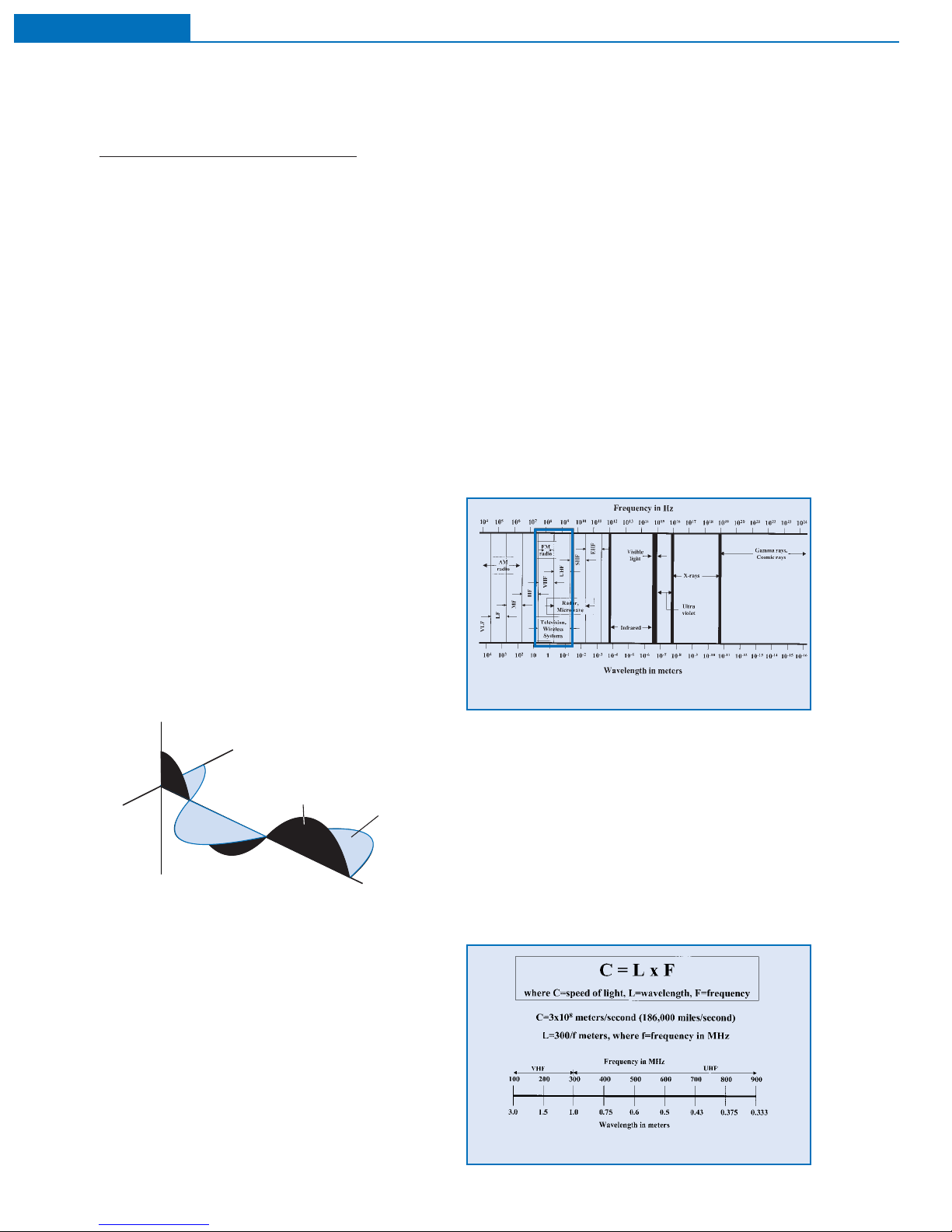
Another characteristic of waves, related to frequency,
is wavelength. The wavelength is the physical distance
between the start of one cycle and the start of the next
cycle as the wave moves through space. Wavelength is
related to frequency by the speed at which the wave
travels through a given medium. This relationship is
expressed in the wave equation, which states that the
speed of the wave is always equal to the product of the
frequency times the wavelength. The wave equation
applies to any physical wave phenomenon such as radio
waves, sound waves, seismic waves, etc. (See Figure 1-3.)
5
Selection
and Operation
of Wireless Microphone Systems
C HAPTER 1
Basic Radio Principles
Figure 1-2: frequency vs. wavelength
Figure 1-1: radio wave
Figure 1-3: the wave equation
Part One: Wireless Microphone Systems: How They Work
y
x
Magnetic Field
Electric Field
The speed of radio waves (through a
vacuum) is equal to approximately 3 x 10
8
meter/second, or about 186,000 miles/
second. This is also known as the "speed of
light," since light is just one part of the radio
spectrum. The wave equation states that the
frequency of a radio wave, multiplied by its
wavelength always equals the speed of light.
Thus, the higher the radio frequency, the
shorter the wavelength, and the lower the
frequency, the longer the wavelength. Typical
wavelengths for certain radio frequencies are
given in Figure 1-3. Wavelength also has important
consequences for the design and use of wireless
microphone systems, particularly for antennas.
Unlike sound, radio waves do not require a physical
substance (such as air) for transmission. In fact, they
"propagate" or travel most efficiently through the vacuum of
space. However, the speed of radio waves is somewhat
slower when travelling through a medium other than
vacuum. For example, visible light travels more slowly
through glass than through air. This effect accounts for the
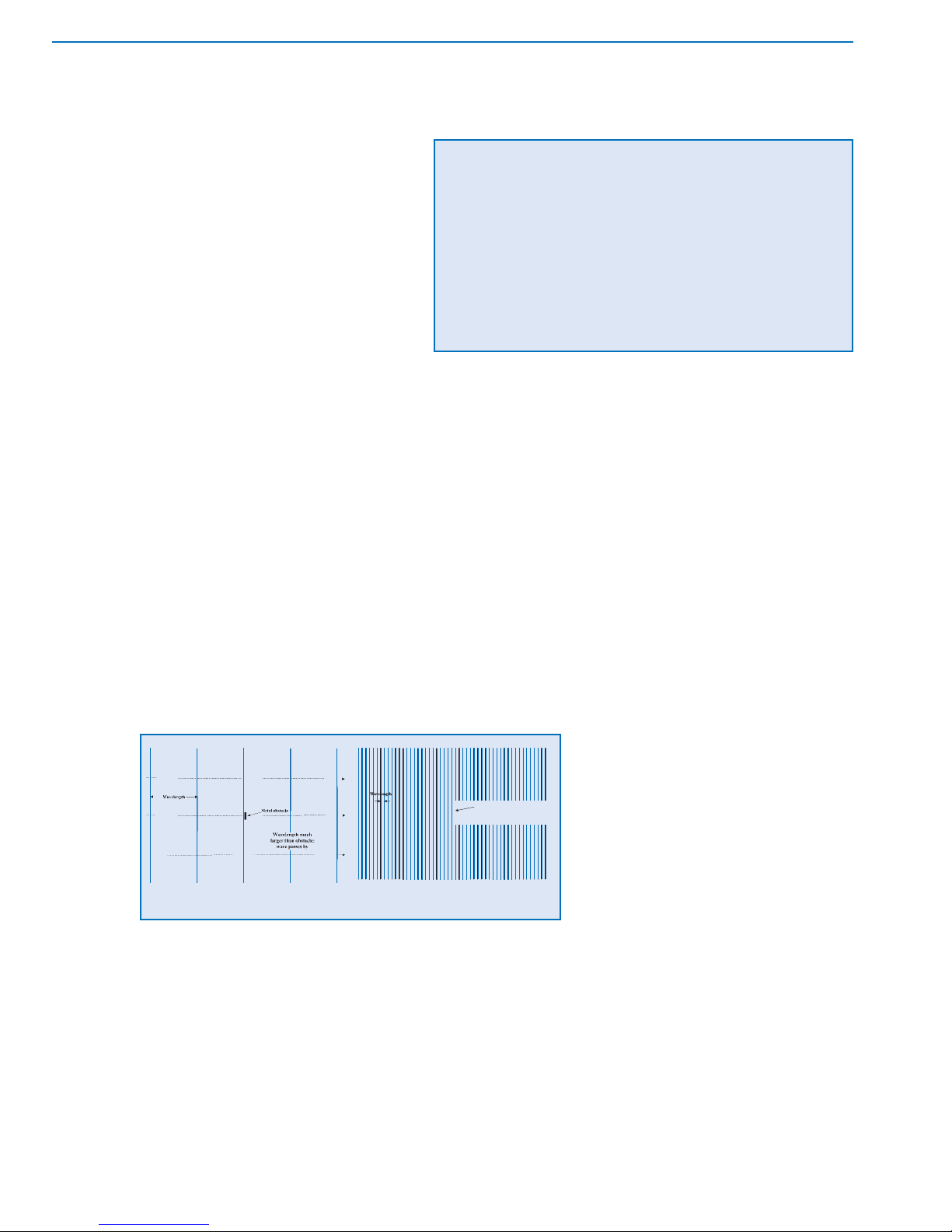
"refraction" or bending of light by a lens. Radio waves can
also be affected by the size and composition of objects in
their path. In particular , they can be reflected by metal objects
if the size of the object is comparable to or greater than the
wavelength of the radio wave. Large surfaces can reflect
both low frequency (long wavelength) and high frequency
(short wavelength) waves, but small surfaces can reflect
only high frequency (short) radio waves. (See Figure 1-5.)
Interestingly, a reflecting metal object can be porous,
that is, it can have holes or spaces in it. As long as the
holes are much smaller than the wavelength, the metal
surface will behave as if it were solid. This means that
screens, grids, bars, or other metal arrays can reflect radio
waves whose wavelength is greater than the space
between the array elements and less than the overall array
size. If the space between elements is larger than the
wavelength, the radio waves will pass through the array.
For example, the metal grid on the glass door of a
microwave oven reflects microwaves back into the oven
but allows light waves to pass through so that the inside is
visible. This is because microwaves have a wavelength of
at least one centimeter while visible light has a wavelength
of only one-millionth of a meter. (See Figure 1-4)
Even metal objects that are somewhat smaller than the
wavelength are able to bend or "diffract" radio waves.
Generally, the size, location, and quantity of metal in the
vicinity of radio waves will have significant effect on their
behavior. Non-metallic substances (including air) do not
reflect radio waves but are not completely transparent either .
To some degree, they generally "attenuate" or cause a loss
in the strength of radio waves that pass through them. The
amount of attenuation or loss is a function of the thickness
and composition of the material and also a function of the
radio wavelength. In practice, dense materials produce
more losses than lighter materials and long radio waves (low
frequencies) can propagate greater distances through
"lossy" materials than short radio waves (high frequencies).
The human body causes significant losses to short radio
waves passing through it.
An object that is large enough to reflect radio
waves or dense enough to attenuate them can
create a "shadow" in the path of the waves which
can greatly hamper reception of radio in the area
beyond the object.
A final parallel between sound waves and
radio waves lies in the nature of the overall radio
wave pattern or "field" produced by various
sources at a given location. If reflections are
present (which is nearly always the case
indoors), the radio field will include both direct
waves (those that travel by the shortest path
from the source to the location) and indirect waves (those
that are reflected). Radio waves, like sound waves, become
weaker as they travel away from their source, at a rate
governed by the inverse-square law: at twice the distance,
the strength is decreased by a factor of four (the square of
two). The strength of radio waves that arrive at a given
location, by direct or indirect paths, is equal to the strength
of the original source(s) minus the amount of loss due to
distance (inverse square loss), loss due to material
attenuation, and loss due to reflections.
After many reflections radio waves become weaker and
essentially non-directional. They ultimately contribute to
Selection
and Operation
of Wireless Microphone Systems
6
C HAPTER 1
Basic Radio Principles

ambient radio "noise," that is, general radio energy
produced by many natural and man-made sources across
a wide range of frequencies. The strength of ambient radio
noise is relatively constant in a given area, that is, it does not
diminish with distance. The total radio field at a given location consists of direct waves, indirect waves and radio noise.
Radio noise is nearly always considered to be
undesirable. The direct and indirect waves may come from
both the desired source (the intended transmission) and
undesirable sources (other transmissions and general radio
energy emitters). Successful radio reception depends on a
favorable level of the desired transmission compared to the
level of undesirable transmissions and noise.
RADIO WAVE MODULATION
This discussion of radio transmission has so far dealt
only with the basic radio wave. It is also necessary to
consider how information is carried by these waves. Audio
"information" is transmitted by sound waves which consist
of air pressure variations over a large range of amplitudes
and frequencies. This combination of varying amplitudes
and varying frequencies creates a highly complex sound
field. These varying pressure waves are able to be
processed directly by our auditory systems to perceive
speech, music, and other intelligible sounds (information).
Radio "information" is generally transmitted using only
one frequency. This single electromagnetic wave is varied
in amplitude, frequency, or some other characteristic (such
as phase) and for most radio transmissions neither the wave
nor its variation can be detected or processed directly by
human senses. In fact, the wave itself is not the
information but rather the "carrier" of the information. The
information is actually contained in the amplitude variation or
frequency variation, for example. When a radio wave
contains information it is called a radio "signal." The
general term for this information-carrying variation of radio
waves is "modulation." If the amplitude of the wave is varied
the technique is called Amplitude Modulation or AM. If the
frequency is varied, it is called Frequency Modulation or FM.
The amount of information that can be carried in a radio
signal depends on the type of modulation and the level of
modulation that can be applied to the basic radio wave. It also
depends on the frequency of the basic radio wave. These
factors are limited by physics to some extent, but are also
limited by regulatory agencies such as the FCC. For AM
signals, the radio wave has a single (constant) frequency of
some basic amplitude (determined by the transmitter power).
This amplitude is varied up and down (modulated) by the
audio signal to create the corresponding radio signal. The rate
of modulation is equal to the frequency of the audio signal and
the amount of modulation is proportional to the amplitude
(loudness) of the audio signal. The maximum (legal) amount
of amplitude modulation allows an audio signal of only limited
frequency response (about 50-9000 Hz) and limited dynamic
range (about 50 dB). (See Figure 1-6.)
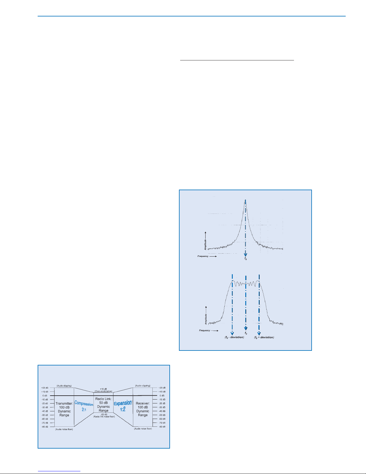
For FM signals, the radio wave has a constant
amplitude (again determined by transmitter power) and
a basic frequency . The basic radio frequency is varied up and
down (modulated) by the audio signal to create the corresponding radio signal. This frequency modulation is called
"deviation" since it causes the carrier to deviate up and down
from its basic or unmodulated frequency . (See Figure 1-7.)
The amount of deviation is a function of the amplitude
of the audio signal and is usually measured in kilohertz
(KHz). Typical values of deviation in wireless microphone
systems range from about 12KHz to 45KHz depending on
the operating frequency band. The maximum (legal)
amount of deviation allows an audio signal of greater
frequency response (about 50-15,000 Hz) and greater
dynamic range (more than 90 dB) than does AM.
Although the details of wireless microphone transmitters
and receivers will be covered in the next section, it should be
noted here that all of the systems discussed in this presentation use the FM technique. The reasons for this are the same
as are apparent in commercial broadcast systems. More
"information" can be sent in the typical FM signal, allowing
higher fidelity audio signals to be transmitted. In addition, FM
receivers are inherently less sensitive to many common
sources of radio noise, such as lightning and electrical power
equipment. These sources are characterized by a high level
of AM-type noise which is rejected by FM systems.
7
Selection
and Operation
of Wireless Microphone Systems
C HAPTER 1
Basic Radio Principles
Figure 1-6: amplitude modulation (AM)
Figure 1-7: frequency modulation (FM)
SYSTEM DESCRIPTION
The function of a radio or "wireless" system is to send
information in the form of a radio signal. In this presentation,
the information is assumed to be an audio signal, but of
course video, data, or control signals can all be sent via
radio waves. In each case, the information must be
converted to a radio signal, transmitted, received, and
converted back to its original form. The initial conversion
consists of using the original information to create a radio
signal by "modulating" a basic radio wave. In the final
conversion, a complementary technique is used to
"demodulate" the radio signal to recover the original
information.
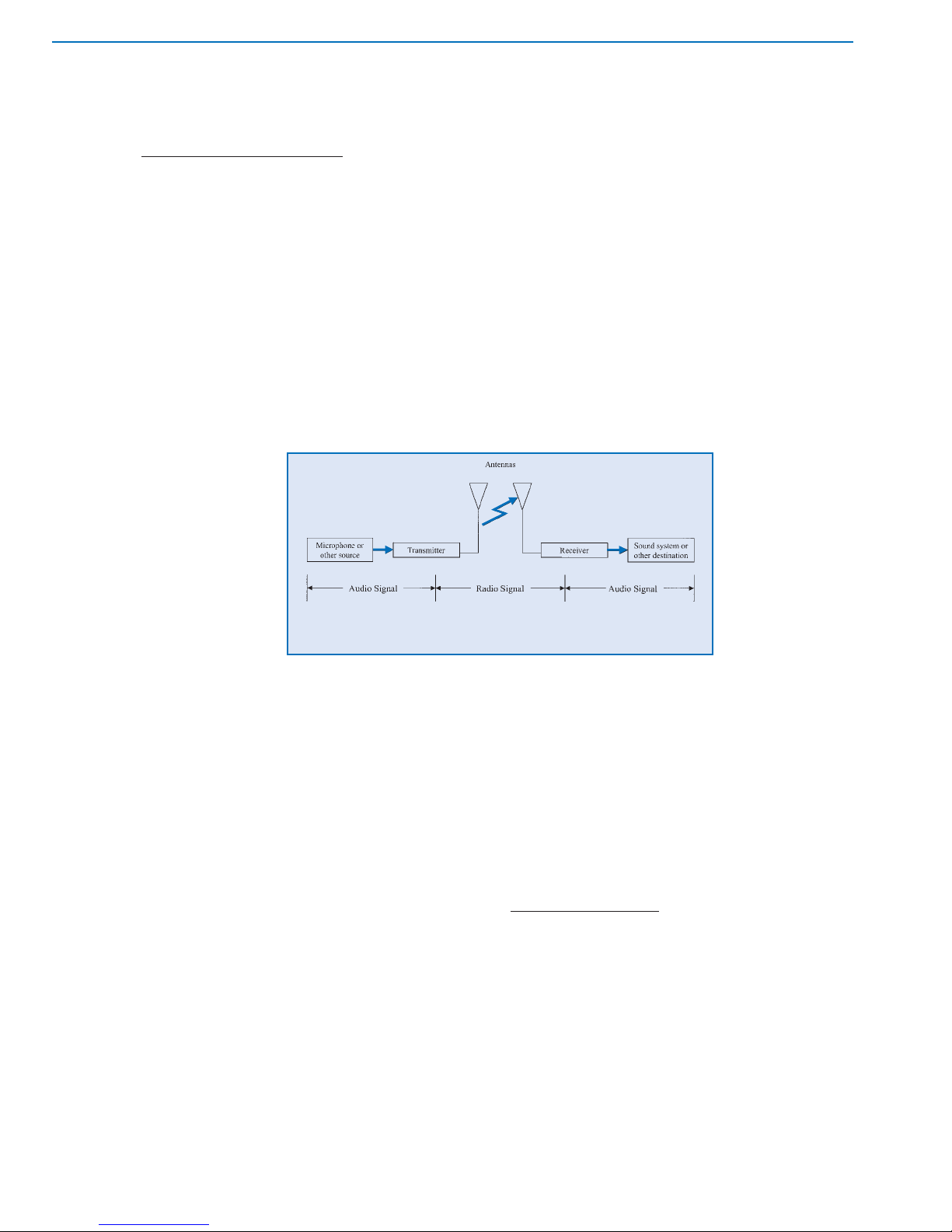
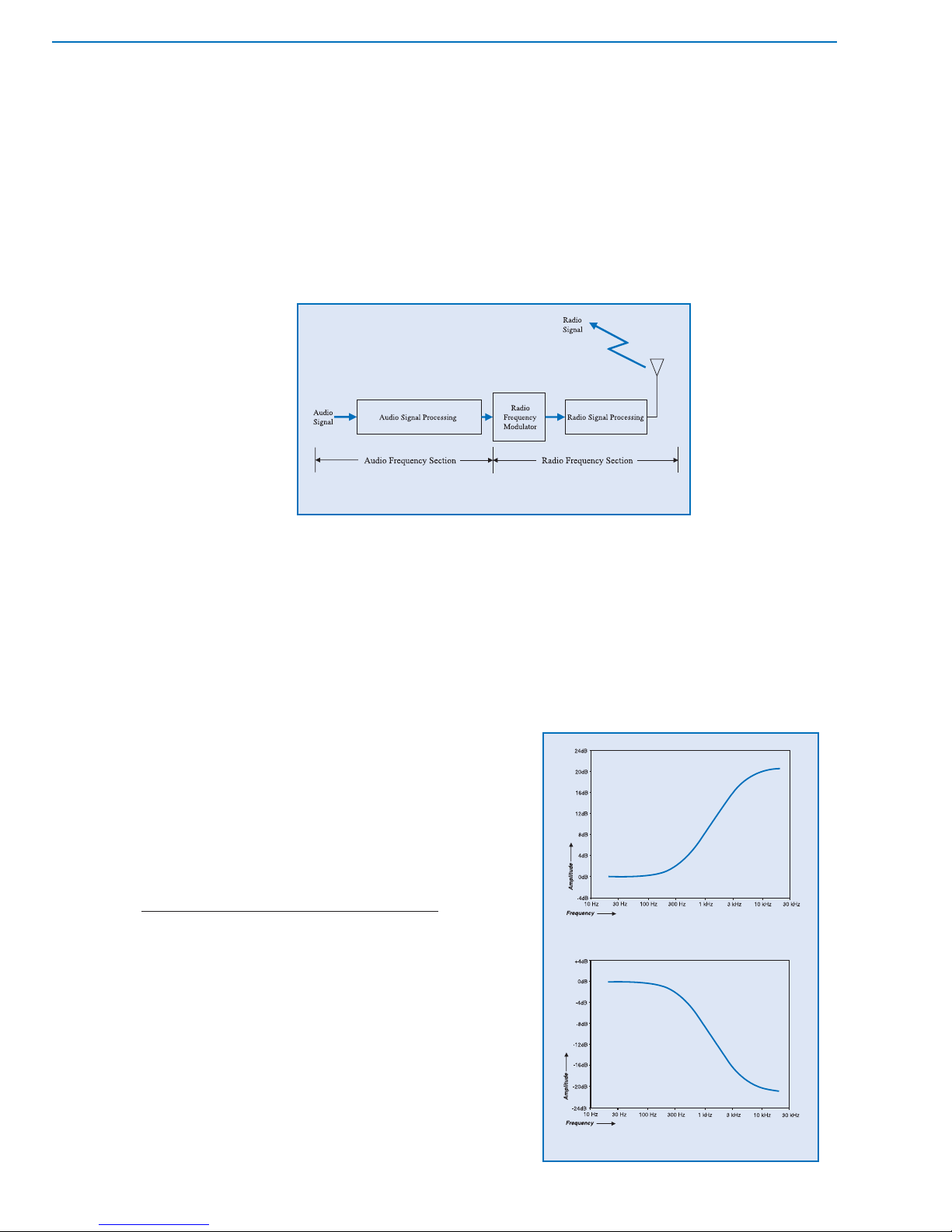
A wireless microphone system consists generally of
three main components: an input source, a transmitter,
and a receiver.
(See Figure 2-1.) The
input source provides
an audio signal to the
transmitter. The
transmitter converts the
audio signal to a radio
signal and "broadcasts"
or transmits it to the
surrounding area.
The receiver "picks
up" or receives the radio signal and converts it back into an
audiosignal. Additional system components include
antennas and, possibly, antenna cables and distribution
systems. The processes and the basic components are
functionally similar to commercial radio and television and
other forms of radio communications. What differs is the
component scale and the physical system configurations.
There are four basic configurations of wireless
microphone systems, related to the mobility of the
transmitter and receiver components, as required for
different applications. The first configuration involves a
portable transmitter and a stationary receiver. The
transmitter is usually carried by the user, who is free to
move about, while the receiver is located in a fixed
position. The input source in this setup is normally a
microphone or an electronic musical instrument. The
receiver output is typically sent to a sound system,
recording equipment, or a broadcast system. This is the
configuration of the standard "wireless microphone" and is
the arrangement most widely used in entertainment,
public address, and broadcast applications.
The second configuration employs a stationary
transmitter and a portable receiver. In this case, the user
carries the receiver , while the transmitter is fixed. The input
source to the transmitter for these setups is usually a
sound system, playback system, or other installed source.
The output of the receiver is typically monitored through
headphones or loudspeakers. It may feed a portable
audio or video recorder. This is the configuration of
wireless systems for in-ear-monitors, (IEMs) interruptible
foldback systems (IFB), assistive listening, simultaneous
translation, and various instructional uses. It is also, of
course, the configuration of commercial radio and
television broadcast systems when the receiver is mobile
such as a personal radio or a car radio.
The third configuration consists of both a portable
transmitter and a portable receiver. The users of both
components are free to move about. Again, the input
source is usually a microphone and the output is often a
headphone. This is the configuration of "wireless
intercom" systems, though each user in a typical setup
has both a transmitter and a receiver for two-way
communication.
Another application
of this configuration
is for transmission
of audio from
a wireless
microphone to a
portable camera/
recorder in
broadcast, film, and
videography.
The fourth configuration comprises a transmitter
and a receiver that are each stationary. Such setups
are often referred to as "point-to-point" wireless
systems. The typical input would be a playback source
or mixer while the output might be to a sound system
or to a broadcast facility. Examples of this setup are
wireless audio feeds to multiple amplifier/loudspeaker
arrays for temporary distributed sound systems, radio
remote-to-studio links and of course commercial and
non-commercial broadcasts from fixed transmitters to
fixed receivers.
INPUT SOURCES
The input source is any device that provides a suitable
audio signal to the transmitter. "Suitable audio signal"
means an electrical signal within a certain frequency range
(audio), voltage range (microphone level or line level), and
impedance range (low or high) that can be handled by the
transmitter. Though this places some limits on input
sources, it will be seen that almost any type of audio
signal can be used with one system or another.
The most common input source is a microphone,
which may take any one of a variety of forms: handheld,
lavaliere, headworn, instrument-mounted, etc. The audio
signal provided by this source is audio frequency,
Selection
and Operation
of Wireless Microphone Systems
8
C HAPTER 2
Basic Radio Systems
Figure 2-1: general radio system diagram
microphone level, and usually low impedance. Since the
"wireless" part of the wireless microphone only serves to
replace the cable, ideally, the characteristics and
performance of a particular microphone should not
change when used as part of a wireless microphone system.
Therefore, the selection of microphone type for a
wireless microphone system should be made following
the same guidelines as for wired microphones. The usual
choices of operating principle (dynamic/condenser),
frequency response (flat/shaped), directionality
(omnidirectional/unidirectional), electrical output
(balanced/unbalanced, low or high impedance), and
physical design (size, shape, mounting, etc.) must still be
made correctly. Problems that result from improper
microphone choice will only be aggravated in a wireless
application.
Another widely encountered input source is an
electronic musical instrument, such as an electric guitar,
electric bass, or portable electronic keyboard. The signal
from these sources is again audio frequency, microphone
or line level, and usually high impedance. The potentially
higher signal levels and high impedances can affect
transmitter choice and operation.
Finally, general audio signal sources such as mixer
outputs, cassette or CD players, etc. may be considered.
These exhibit a wide range of levels and impedances.
However, as long as these characteristics are within the
input capabilities of the transmitter they may be
successfully used.
TRANSMITTER:
GENERAL DESCRIPTION
Transmitters can be either fixed or portable as mentioned earlier . Regardless of type, transmitters usually feature a single audio input (line or microphone type), minimal
controls and indicators (power, audio gain adjustment)
and a single antenna. Internally, they are also functionally
the same, except for the power supply: AC power for fixed
types and battery power for portable models. The
important features of transmitter design will be presented
in the context of portable units.
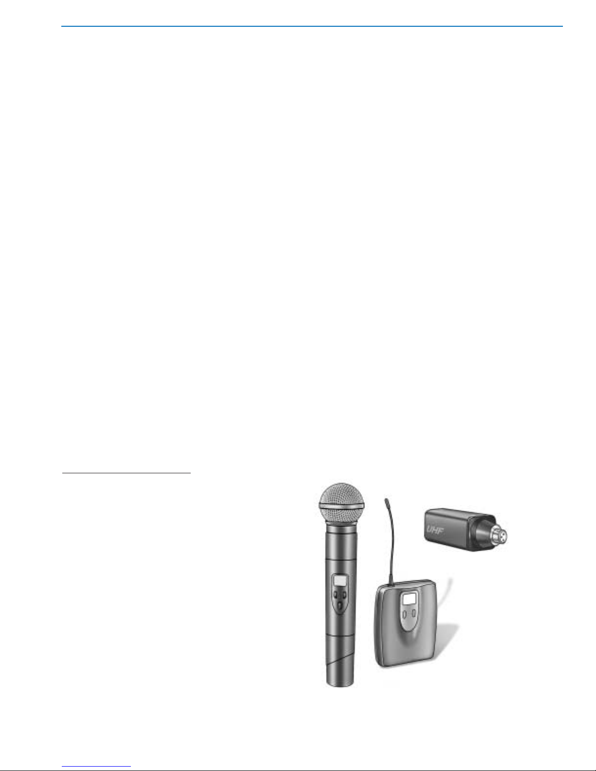
Portable transmitters are available in three different
forms: bodypack, handheld, and plug-on. (See Figure 2-2.)
Each of these has further variations of inputs, controls,
indicators, and antennas. The choice of transmitter type
is often dictated by the choice of input source: handheld
microphones usually require handheld or plug-on
transmitters while nearly all other sources are used with
bodypack types.
Bodypack (sometimes called beltpack) transmitters
are typically packaged in a shirt-pocket sized rectangular
housing. They are often provided with a clip that secures
to clothing or belt, or may be placed in a pocket or pouch.
In theater and some other applications they may be
concealed underneath clothing. Input is made from the
source to the bodypack via a cable, which may be
permanently attached or detachable at a connector. This
connector may allow a variety of input sources to be used
with one transmitter.
Bodypack transmitter controls include at least a power
switch and often a separate mute switch, allowing the
audio input to be silenced without interrupting the radio
signal. Other controls may include gain adjustment,
attenuators, limiters and, in tuneable systems, a provision
for frequency selection. Indicators (usually LED’s) for
power-on and battery condition are desirable, while
tuneable units sometimes include digital readouts of
frequency. A few transmitters are equipped with audio
"peak" indicators. Finally, the antenna for a bodypack
transmitter may be in the form of a flexible attached wire, a
short "rubber ducky" type, or the input source cable itself,
such as a guitar cable or lavaliere microphone cable.
Handheld transmitters, as the name implies, consist of
a handheld vocal microphone element integrated with a
transmitter built into the handle. The complete package
appears only slightly larger than a wired handheld
microphone. It may be carried in the hand or mounted on
a microphone stand using an appropriate swivel adapter.
Input from the microphone element is direct via an internal
connector or wires. Some models have removable or
interchangeable microphone elements.
9
Selection
and Operation
of Wireless Microphone Systems
C HAPTER 2
Basic Radio Systems
Figure 2-2:
examples of transmitters (left to right: handheld, bodypack, plug-on)
Handheld transmitter controls are generally limited
to a power switch, a mute switch, and gain adjustment.
Again, tuneable models include some provision for
frequency selection. Indicators are comparable to
those in bodypack transmitters: power status, battery
condition, frequency. Handheld transmitter antennas
are usually concealed internally, though certain types
(primarily UHF) may use a short external antenna.
"Plug-on" transmitters are a special type
designed to attach
directly to a typical
handheld microphone,
effectively allowing
many standard microphones to become
"wireless." The transmitter is contained in a
small rectangular or
cylindrical housing with
an integral female XLR-type input connector . Controls and
indicators are comparable to those found in bodypack
types and the antenna is usually internal.
Miniaturization of components has also resulted in a
class of transmitters that are integrated directly into
headworn microphones and lapel microphones as well as
units that can plug directly into the output connector of an
electric guitar. The trend toward smaller and more highly
integrated devices is certain to continue.
While transmitters vary considerably in their external
appearance, internally they all must accomplish the same
task: use the input audio signal to modulate a radio
carrier and transmit the resulting radio signal effectively.
Though there are many different ways to engineer wireless
transmitters, certain functional elements are common to
most current designs. It is useful to describe these
elements to gain some insight to the overall performance
and use of wireless microphone systems. (See Figure 2-3.)
TRANSMIT
TER: AUDIO CIRCUITRY
The first part of the typical transmitter is the input circuitry.
This section makes the proper electrical match between the
input source and the rest of the transmitter . It must handle the
expected range of input levels and present the correct
impedance to the source. Gain controls and impedance
switches allow greater flexibility in some designs. In certain
cases, the input circuitry also provides electrical power to the
source (for condenser microphone elements).
The signal from the input stage passes to the signal
processing section, which optimizes the audio signal in
several ways for the constraints imposed by radio
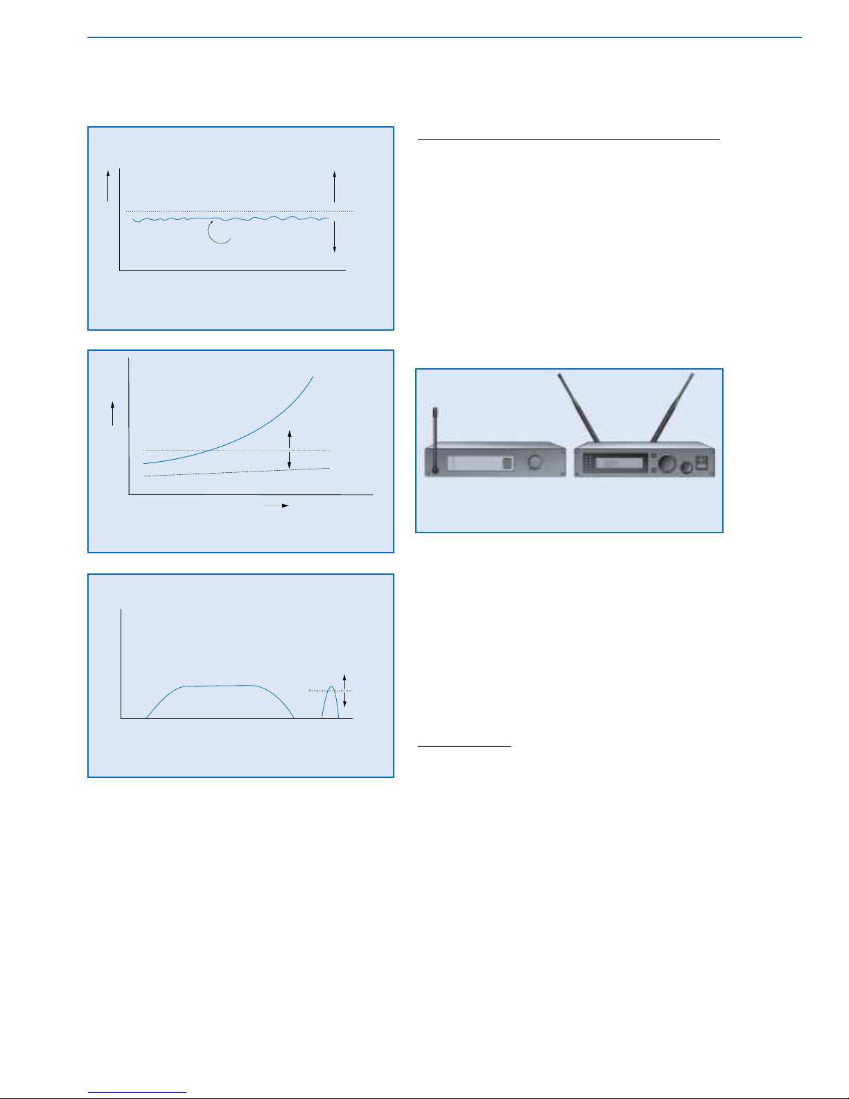
transmission. The first process is a special equalization
called pre-emphasis, which is designed to minimize the
apparent level of high frequency noise (hiss) that is
unavoidably added during the transmission. The "emphasis"
is a specifically tailored boost of the high frequencies.
When this is coupled with an equal (but opposite)
"de-emphasis" in the receiver, the effect is to reduce high
frequency noise by up to 10 dB. (See Figures 2-4 a & b.)
The second process is called "companding"
(compress/expand),
which is designed to
compensate for the
limited dynamic range of
radio transmission. The
part of the process
performed in the transmitter is "compression,"
in which the dynamic
range of the audio
signal is reduced or
compressed, typically by
a fixed ratio of 2:1. Again, when this is coupled with an equal
but opposite (1:2) "expansion" of the signal in the receiver,
the original dynamic range of the audio signal is restored. A
voltage-controlled-amplifier (VCA) is the circuit element that
provides both dynamic functions: gain is decreased in the
compressor mode and increased in the expander mode.
The gain change is proportional to the signal level change.
Nearly all current wireless microphone systems employ
some form of companding, allowing a potential dynamic
range greater than 100 dB. (See Figure 2-5.)
Selection
and Operation
of Wireless Microphone Systems
10
C HAPTER 2
Basic Radio Systems
Figure 2-4b: de-emphasis in transmitter
Figure 2-4a: pre-emphasis in transmitter
Figure 2-3: general transmitter block diagram
A variation that is found in a few compander designs is
to divide the audio signal into two or more frequency bands.
Each band is then pre-emphasized and compressed
independently . In the receiver, de-emphasis and expansion
are applied separately to these same bands before
combining them back into a full-range audio signal. Though
more expensive, multi-band companding systems may
have a better ability to improve dynamic range and
apparent signal-to-noise ratio across the entire audio range.
A limitation of fixed-ratio companders is that the same
amount of signal processing is applied regardless of
signal level. Dynamics processors perform compression
or expansion functions based on an evaluation of the
"average" signal level, which fluctuates continuously.
Because this process is not instantaneous, the compander
action is not completely transparent. With good design,
audible "artifacts" are minimal but may become more
apparent when the signal level is extremely low. This
accounts for occasional "modulation" noise or background
noise intrusion that accompanies low-level audio signals,
especially when the radio signal itself is weak or noisy.
The performance of full-band companding systems can
be improved by first optimizing the measurement of the
average signal level. A "true RMS" detector is preferred,
since this technique most closely tracks the amplitude of a
full range audio signal, regardless of frequency response.
Further improvement can be realized by using leveldependent companding. For low level audio signals, little
or no processing is applied so there are no audible effects.
As the audio signal level increases, processing levels are
increased, so that potentially audible artifacts are masked.
Implementation of this scheme requires a high
performance VCA and close tolerance in the audio
sections of transmitters and receivers.
In many transmitters, an additional process called limiting
is applied to the audio signal. This is to prevent overload and
distortion in subsequent audio stages or to prevent
"overmodulation" (excessive frequency deviation) of the radio
signal. The "limiter" automatically prevents the audio signal
level from exceeding some preset maximum level and is
usually applied after pre-emphasis and companding.
TRANSMITTER: RADIO CIRCUITRY
After processing, the audio signal is sent to a voltagecontrolled oscillator (VCO). This is the section that actually
converts the audio signal to a radio signal by the technique
called frequency modulation (FM). The (relatively) low
frequency audio signal controls a high frequency oscillator
to produce a radio signal whose frequency "modulates" or
varies in direct proportion to the audio signal.
The maximum value of modulation is called the
deviation and is specified in kilohertz (KHz). The amount of
deviation produced by the audio signal is a function of the
design of the transmitter. Systems with deviation greater
than the modulating frequency are called wideband, while
systems with deviation less than the modulating frequency
are called narrow band. Most wireless microphone
transmitters fall into the upper end of the narrow band
category . (See Figures 2-6 a & b.)
The "base" or unmodulated frequency of the oscillator for
a single frequency system is fixed. By design, the
frequency of the signal from the VCO (for a conventional,
crystal-controlled transmitter) is much lower than the desired
output frequency of the transmitter . In order to achieve a given
transmitter frequency the output from the VCO is put through
a series of frequency multiplier stages. These multipliers are
usually a combination of doublers, triplers, or even quadruplers.
For example, a transmitter that employs two triplers (for a 9x
multiplication) would use a VCO with a base frequency of 20
MHz to achieve a 180 MHz transmitted frequency. The
multipliers also function as amplifiers so that the output signal
is at the desired power level as well. (See Figure 2-7.)
11
Selection
and Operation
of Wireless Microphone Systems
C HAPTER 2
Basic Radio Systems
Figure 2-5: compander (2:1, fixed rate)
Figure 2-6b: modulated FM signal spectrum
Figure 2-6a: unmodulated FM signal spectrum
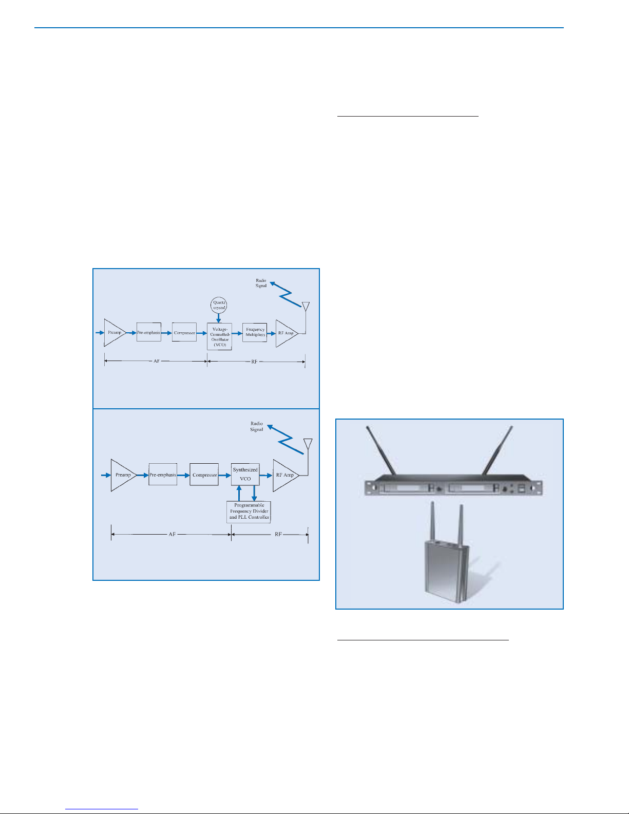
A few tuneable transmitters use multiple crystals to
obtain multiple frequencies. However , the base frequency
of the VCO for most tuneable systems is adjustable by a
technique known as frequency synthesis. A control circuit
called a phase-locked-loop (PLL) is used to calibrate the
transmitter frequency to a reference "clock" frequency
through an adjustable frequency divider. By changing the
divider in discrete steps, the transmitter frequency can be
precisely varied or tuned over the desired range.
Frequency-synthesized designs allow the audio signal to
modulate the VCO directly at the transmitter frequency . No
multiplier stages are required. (See Figure 2-8.)
The last internal element of the transmitter is the
power supply. For portable transmitters, power is
generally supplied by batteries. Since the voltage level
of batteries falls as they are discharged, it is necessary
to design the device to operate over a wide range of
voltage and/or to employ voltage-regulating circuitry.
Most designs, especially those requiring a 9 V battery,
use the battery voltage directly. Others, typically those
using 1.5 V cells, have DC-to-DC converters that boost
the low voltage up to the desired operating value.
Battery life varies widely among transmitters, from just
a few hours up to twenty hours, depending on output
power, battery type, and overall circuit efficiency.
RECEIVER:
GENERAL DESCRIPTION
Receivers are available in both fixed and portable
designs. (See Figure 2-9.) Portable receivers resemble
portable transmitters externally: they are characterized by
small size, one or two outputs (microphone/line, headphone), minimal controls and indicators (power , level), and
(usually) a single antenna. Internally they are functionally
similar to fixed receivers, again with the exception of the
power supply (battery vs. AC). The important features
ofreceivers will be presented in the context of fixed units,
which exhibit a greater range of choices.
Fixed receivers offer various outward features: units
may be free standing or rack-mountable; outputs may
include balanced/unbalanced microphone or line level as
well as headphones; indicators for power and audio/radio
signal level may be present; controls for power and output
level are usually offered; antennas may be removable or
permanently attached. Like transmitters, receivers can
vary greatly in packaging, but inside they must achieve a
common goal: receive the radio signal efficiently and
convert it into a suitable audio signal output. Once again
it will be useful to look at the main functional elements of
the typical receiver. (See Figure 2-10.)
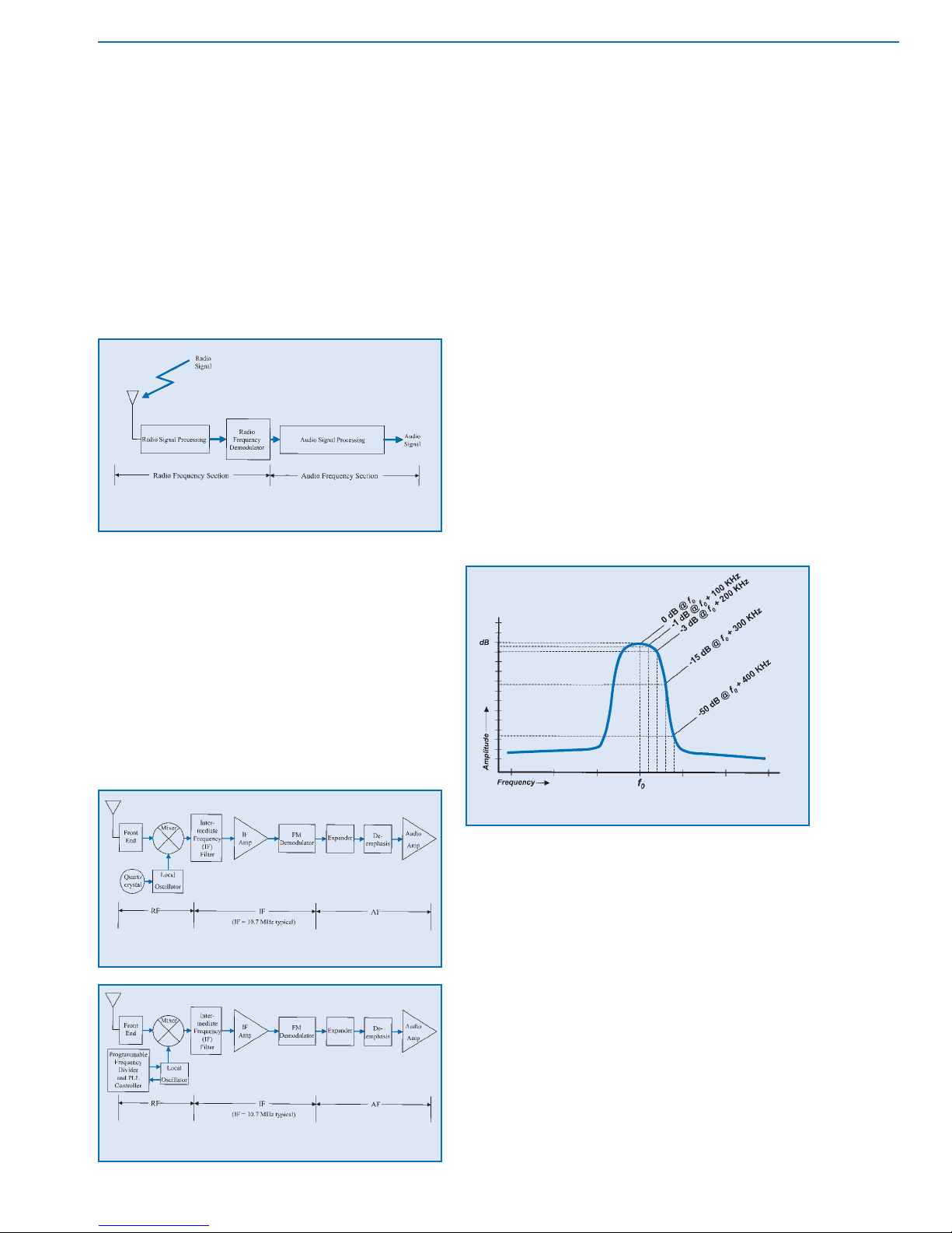
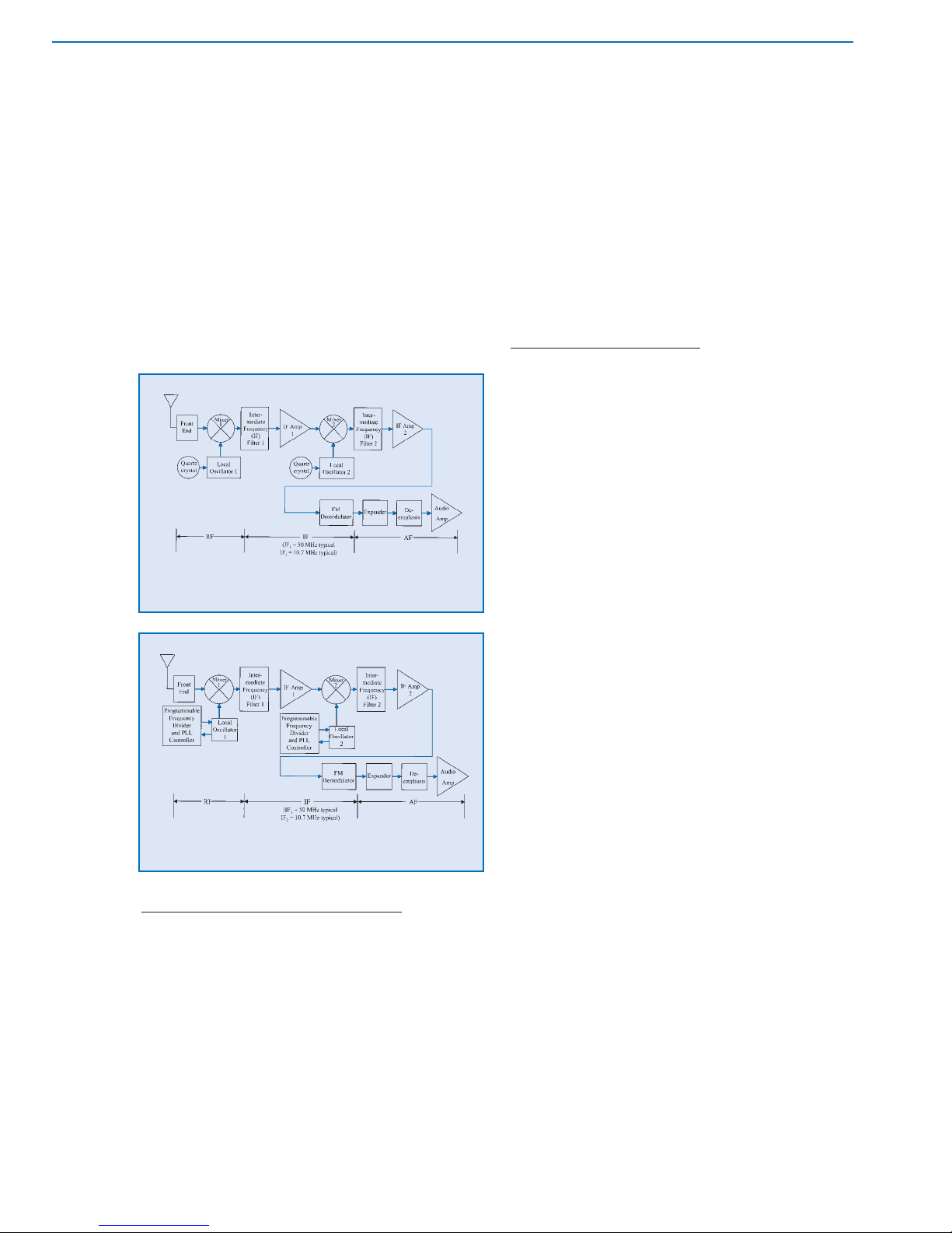
RECEIVER: RADIO CIRCUITRY
The first section of receiver circuitry is the "front end."
Its function is to provide a first stage of radio frequency
(RF) filtering to prevent unwanted radio signals from
causing interference in subsequent stages. It should
effectively reject signals that are substantially above or
below the operating frequency of the receiver . For a single
frequency receiver the front end can be fairly narrow. For a
tuneable receiver it must be wide enough to accommodate
the desired range of frequencies if the front end filter itself
Selection
and Operation
of Wireless Microphone Systems
12
C HAPTER 2
Basic Radio Systems
Figure 2-7: crystal-controlled transmitter
Figure 2-8: frequency-synthesized transmitter
Figure 2-9:
receiver examples
fixed
portable
is not tuneable. Filter circuits of various types ranging from
simple coils to precision "helical resonators" are used in front
end filters. The second receiver section is the "local
oscillator" (usually abbreviated as "LO"). This circuit
generates a constant radio frequency that is related to the
frequency of the received radio signal but differs by a
"defined amount." Single frequency receivers have a fixed
frequency local oscillator (LO), again using a quartz crystal.
Tuneable receivers have an adjustable LO, which generally
uses a frequency synthesis design. (See Figures 2-11 a & b.)
Next, the (filtered) received signal and the local
oscillator output are input to the "mixer" section. The mixer ,
in a radio receiver, is a circuit that combines these signals
in a process called "heterodyning." This process produces
two "new" signals: the first new signal is at a frequency
which is the sum of the received signal frequency and the
local oscillator frequency , while the second is at a frequency
which is the difference between the received signal
frequency and the local oscillator frequency . Both the sum
and the difference signals contain the audio information
carried by the received signal. It should be noted that the
LO frequency can be above or below the received
frequency and still yield the same difference frequency
when combined in the mixer. When the LO frequency is
lower than the received frequency the design is called
"low-side injection." When it is above it is called "high-side
injection." The sum and difference signals are then sent to
a series of filter stages that are all tuned to the frequency
of the difference signal. This frequency is the
"intermediate frequency" (IF), so-called because it is lower
than the received radio frequency but still higher than the
final audio frequency . It is also the "defined amount" used
to determine the local oscillator frequency of the previous
section. The narrowly tuned IF filters are designed to
completely reject the sum signal, as well as the LO
frequency and the original received signal, and any other
radio signals that may have gotten through the front end.
The IF filters allow only the difference signal to pass
through. (See Figure 2-12.) This effectively converts the
received radio frequency (RF) signal to the much lower
intermediate frequency (IF) signal and makes subsequent
signal processing more efficient. This overall process is
called "downconversion."
If only one LO and one mixer stage are used then only
one intermediate frequency is produced and the receiver
is said to be a "single conversion" type. In a "double
conversion" receiver the incoming signal is converted to
the final IF in two successive stages, each with its own LO
and mixer. This technique can provide increased stability
and interference rejection, though at significantly higher
design complexity and cost. Double conversion is more
common in UHF receiver designs where the received
signal frequency is extremely high. (See Figures 2-13 a & b.)
The IF signal is finally input to the "detector" stage
which "demodulates" or extracts the audio signal by one of
several methods. One standard technique is known as
"quadrature." When two signals are out of phase with each
other by exactly 90 degrees they are said to be in
quadrature. When such signals are multiplied together
and low-pass filtered the resulting output signal consists
13
Selection
and Operation
of Wireless Microphone Systems
C HAPTER 2
Basic Radio Systems
Figure 2-11a: single conversion, crystal-controlled receiver
Figure 2-11b: single conversion, frequency-synthesized receiver
Figure 2-10: general receiver block diagram
Figure 2-12: receiver, filter characteristic
only of frequency variations of the original input signal.
This effectively eliminates the (high-frequency) carrier
frequency leaving only the low-frequency modulation
information (the original audio signal).
In a quadrature FM detector the IF signal passes
through a circuit which introduces a 90 degree phase shift
relative to the original IF signal. The phase-shifted IF
signal is then multiplied by the straight IF signal. A
low-pass filter is applied to the product, which results in a
signal that is now the audio signal originally used to
modulate the carrier in the transmitter.
RECEIVER: A
UDIO CIRCUITRY
The demodulated audio signal undergoes
complementary signal processing to complete the
dynamic range recovery and noise reduction action begun
in the transmitter . For conventional compander systems, a
1:2 expansion is applied, followed by a high-frequency
de-emphasis. If a multi-band process was used in the
transmitter, the received audio is divided into the
corresponding bands, each band is expanded, the high
frequency band is de-emphasized, and finally the bands
are recombined to yield the full-range audio signal.
In the case of a signal-dependent compression
system, complementary variable expansion is used
followed by high frequency de-emphasis. Again, a
precision VCA with a true-rms audio level detector is required.
Finally, an output amplifier supplies the necessary
audio signal characteristics (level and impedance) for
connection to an external device such as a mixer input, a
recorder, headphones, etc. Typically, better receivers will
include a balanced output that can be switched between
line level and microphone level. Unbalanced outputs are
usually provided as well.
RECEIVER: SQUELCH
One additional circuit that is important to proper receiver
behavior is called "squelch" or muting. The function of this
circuit is to mute or silence the audio output of the
receiver in the absence of the desired radio signal. When
the desired signal is lost (due to multi-path dropout, excessive distance, loss of power to the transmitter, etc.) the
"open" receiver may pick up another signal or
background radio "noise." T ypically , this is heard as "white"
noise and is often much louder than the audio signal from
the desired source.
The traditional squelch circuit is an audio switch
controlled by the radio signal level using a fixed or
manually adjustable threshold (level). (See Figure 2-14.)
When the received signal strength falls below this level the
output of the receiver is muted. Ideally, the squelch level
should be set just above the background radio noise level
or at the point where the desired signal is becoming too
noisy to be acceptable. Higher settings of squelch level
require higher received signal strength to unmute the
receiver. Since received signal strength decreases as
transmission distance increases, higher squelch settings
will decrease the operating range of the system.
One refinement of the standard squelch circuit is
referred to as "noise squelch." (See Figure 2-15.) This
technique relies on the fact that the audio from undesirable
radio noise has a great deal of high frequency energy
compared to a typical audio signal. The noise squelch
circuit compares the high frequency energy of the
received signal to a reference voltage set by the squelch
adjustment. In this system the squelch control essentially
determines the "quality" of signal (signal-to-noise ratio)
required to unmute the receiver. This allows operation at
lower squelch settings with less likelihood of noise if the
desired signal is lost.
A further refinement is known as "tone-key" or "tonecode" squelch. (See Figure 2-16.) It enables the receiver to
identify the desired radio signal by means of a supra- or
sub-audible tone that is generated in the transmitter and
sent along with the normal audio signal. The receiver will
unmute only when it picks up a radio signal of adequate
strength and also detects the presence of the tone-key.
Selection
and Operation
of Wireless Microphone Systems
14
C HAPTER 2
Basic Radio Systems
Figure 2-13a: double conversion, crystal-controlled receiver
Figure 2-13b: double conversion, frequency-synthesized receiver
This effectively prevents the possibility of noise from the
receiver when the desired transmitter signal is lost, even
in the presence of a (non-tone-key) interfering signal at
the same frequency. Turn-on and turn-off delays are
incorporated in the transmitter tone-key circuits so that
the transmitter power switch operates silently. When the
transmitter is switched on, the radio signal is activated
immediately but the tone-key is briefly delayed, keeping
the receiver muted until the signal is stable. This masks
any turn-on noise. When the transmitter is switched off,
the tone-key is deactivated instantly, muting the receiver,
but actual turn-off of the transmitted signal is delayed
slightly. This masks any turn-off noise. As a result, the
need for a separate mute switch is eliminated.
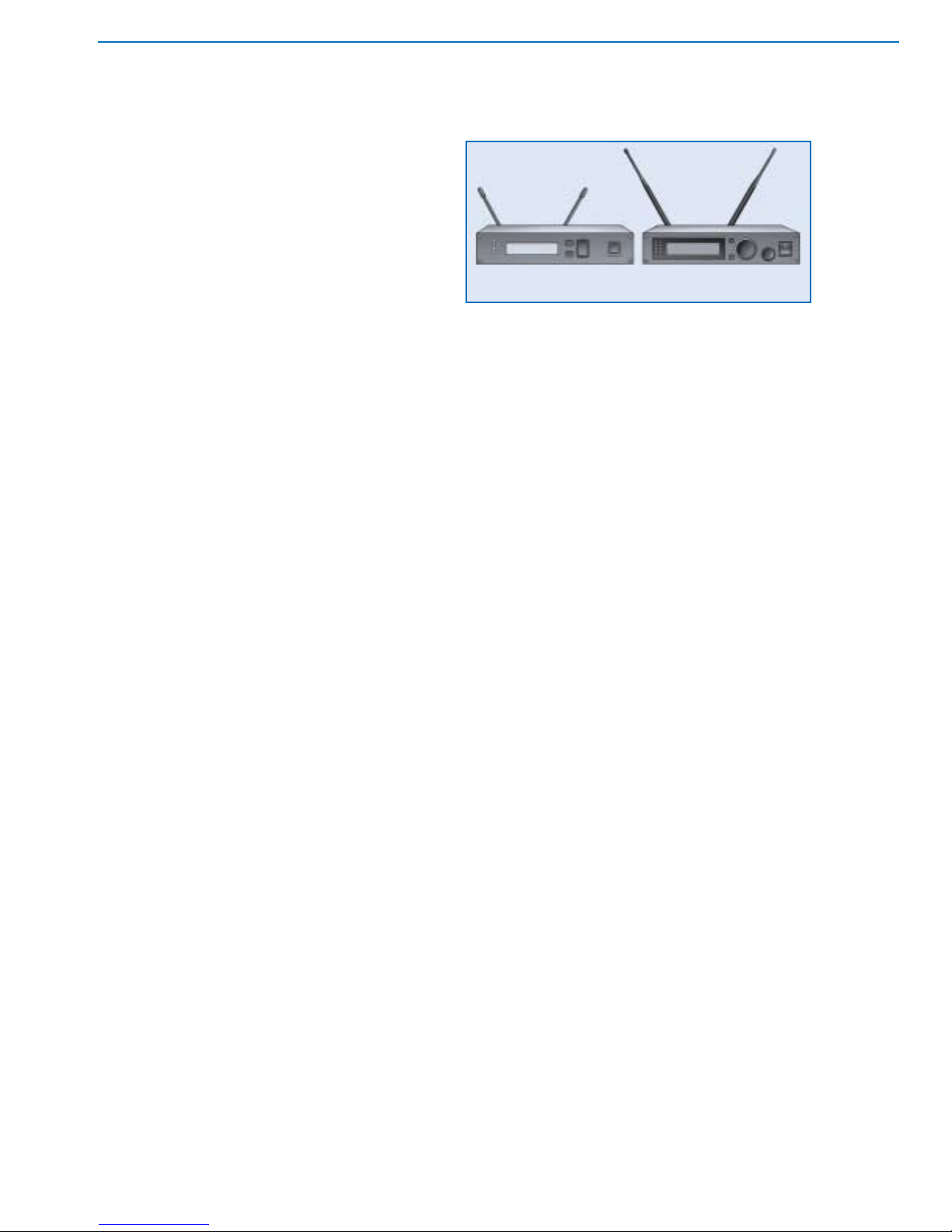
RECEIVER:ANTENNA CONFIGURATION
Fixed receivers are offered in two basic external
configurations: diversity and non-diversity. Non-diversity
receivers are equipped with a single antenna while
diversity receivers generally have two antennas. Both
systems may offer otherwise similar outward features:
units may be free standing or rack-mountable; outputs
may include balanced/ unbalanced microphone or line
level as well as head-phones; indicators for power and
audio/radio signal level may be present; controls for power
and audio output level are provided; antenna(s) may be
removable or permanently attached. (See Figure 2-17.)
Though diversity receivers tend to include more
features than non-diversity types, the choice of diversity vs.
non-diversity receiver is usually dictated by performance and
reliability considerations. Diversity receivers can significantly
improve both qualities by minimizing the effect of variations in
radio signal strength in a given reception area due to fading or
due to multi-path. Fading is a loss of signal strength at
excessive distance or because of shadowing or blocking of the
radio wave. Multi-path is a more complex phenomenon but
both mechanisms can adversely affect radio reception.
MULTIPATH
A necessary element in the concept of diversity radio
reception is the occurrence of "multi-path" effects in radio
transmission. In the simplest case, radio waves proceed
directly from the transmitting antenna to the receiving antenna
in a straight line. The received signal strength is only a function
of the transmitter power and the distance between the
transmitting and receiving antennas. In practice, this situation
could only occur outdoors on level, unobstructed terrain.
In most situations, however, there are objects that
attenuate radio waves and objects that reflect them. Since
both the transmitting and receiving antennas are essentially
omnidirectional, the receiving antenna picks up a varying
combination of direct and reflected radio waves. The reflected
waves and direct waves travel different distances (paths) to
arrive at the receiving antenna, hence the term multi-path.
(See Figure 2-18.)
15
Selection
and Operation
of Wireless Microphone Systems
C HAPTER 2
Basic Radio Systems
Figure 2-17: examples of receivers
RF
Level
Radio Frquency
un-muted
muted
squelch
threshold
RF signal
and noise
Figure 2-14: threshold squelch
AF
Level
Audio Frequency
20 Hz 20 kHz
32 kHz
tone
tone squelch
threshold
un-mute
mute
Figure 2-16: tone key squelch
Figure 2-15: noise squelch
AF
Noise
Level
Audio Frequency
RF Noise
Audio
Characteristic
Noise Squelch
Threshold
Audio
Characteristic
muted
unmuted
non-diversity (single antenna) diversity (two antennas)
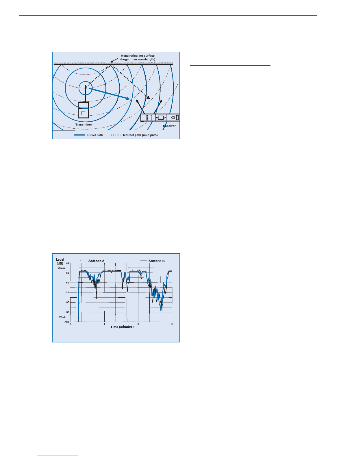
These multiple paths result in differing levels, arrival times
and phase relationships between the radio waves. The net
received signal strength at any location is the sum of the
direct and reflected waves. These waves can
reinforce or interfere with each other depending on their
relative amplitude and phase. The result is substantial
variation in average signal strength throughout an area.
This creates the possibility of degradation or loss of the
radio signal at certain points in space, even when the
transmitter is at a relatively short distance from the
receiver. Cancellation of the signal can occur when the
direct and indirect waves are similar in amplitude and
opposite in phase. (See Figure 2-19.)
The audible effects of such signal strength variation
range from a slight swishing sound ("noise-up"), to severe
noises ("hits"), to complete loss of audio ("dropout"). Similar
effects are sometimes noted in automobile radio reception
in areas with many tall buildings. The "size" of a dropout
region is related to wavelength: in the VHF range (long
wavelength) dropout areas are larger but farther apart, while
in the UHF range (short wavelength) they are smaller but
closer together . For this reason, multi-path effects tend to be
more severe in the UHF range. These effects are
unpredictable, uncomfortable, and ultimately unavoidable
with single-antenna (non-diversity) receivers.
RECEIVER:
DIVERSITY TECHNIQUES
Diversity refers to the general principle of using
multiple (usually two) antennas to take advantage of the
very low probability of simultaneous dropouts at two
different antenna locations. "Different" means that the
signals are statistically independent at each location. This
is also sometimes called "space diversity," referring to the
space between the antennas.
For radio waves, this "de-correlation" is a function of
wavelength: a separation of one wavelength results in nearly
complete de-correlation. In most cases, at least one-quarter
wavelength separation between antennas is necessary for
significant diversity effect: about 40 cm for VHF systems and
about 10 cm for UHF systems. Some increased benefit may
be had by greater separation, up to one wavelength.
Separation beyond one wavelength does not significantly
improve diversity performance, but larger areas may be
covered due to more favorable antenna placement.
There are a number of diversity techniques that have
had some degree of success. The term "true" diversity has
come to imply those systems which have two receiver
sections, but technically, any system which samples the
radio field at two (or more) different locations, and can
"intelligently" select or combine the resulting signals is a
true diversity system.
The simplest technique, called "passive antenna
combining" utilizes a single receiver with a passive combination of two or three antennas. Antennas combined in this
manner create an "array," which is essentially a single
antenna with fixed directional characteristic. In its most
effective form (three antennas, each at right angles to the
other two) it can avoid complete dropouts, but with a
reduction of maximum range. This is because the array
output will almost always be less than the output of a
single antenna at the optimum location. If only two
antennas are used, dropouts can still occur in the event of
an out-of-phase condition between them. Cost is relatively
low but setup of multiple antennas can be somewhat
cumbersome. This is not a "true" diversity design.
(See Figure 2-20.)
A true diversity variation of this technique is "antenna
phase diversity." It also employs two antennas and a
single receiver but provides an active combining circuit for
the two antennas. This circuit can switch the phase of one
antenna relative to the other, eliminating the possibility of
phase cancellation between them. However, switching
noise is possible as well as other audible effects if
switching is incorrect. Range is sometimes greater with
favorable antenna combinations. Cost is relatively low.
Setup requires somewhat greater antenna spacing for
best results. (See Figure 2-21.)
Selection
and Operation
of Wireless Microphone Systems
16
C HAPTER 2
Basic Radio Systems
Figure 2-18: multipath
Figure 2-19: signal level at two antennas with multipath
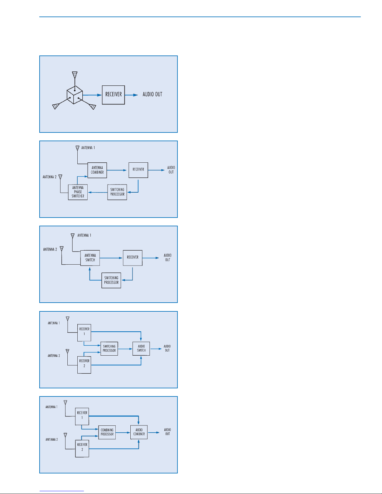
The next variation, "antenna switching diversity," again
consists of a single receiver with two antennas. The receiver
includes circuitry that selects the antenna with the better
signal according to an evaluation of the radio signal.
Switching noise is possible but this system avoids the
possibility of phase cancellation between antennas
because the antennas are never combined. Range is the
same as for a single antenna system. Cost is relatively low
and setup is convenient. (See Figure 2-22.)
In both of these active antenna diversity approaches, the
switching decision is based on the received signal quality of
a single receiver section. When the signal quality falls below
some preset threshold, switching occurs immediately . If the
new antenna (or antenna combination) doesn’t improve the
reception, the receiver must switch back to the original state.
The lack of "predictive" ability often causes unnecessary
switching, increasing the chance of noise. The switching
speed is also critical: too fast and audible noise occurs, too
slow and a dropout may occur.
A recent antenna switching method offers predictive
diversity capability using a microcontroller to optimize
switching characteristics. A running average signal level
and a maximum signal level are calculated by analyzing
the change in signal level over time. Comparing the
current average signal level to the most recent maximum
signal level determines the switch action, based on typical
dropout characteristics. Small declines at high signal
levels indicate impending dropout, causing a switch to
occur. At moderate signal levels, larger decreases are
allowed before switching. At very low signal levels
switching is curtailed to avoid unnecessary noise. Of
course, if the signal level is increasing, no switching
occurs. The onset of dropout can be more accurately
recognized and countered, while eliminating switching
when there is little likelihood for improvement.
"Receiver switching diversity" is a widely used diversity
system. It consists of two complete receiver sections, each
with its own associated antenna, and circuitry that selects the
audio from the receiver that has the better signal. Switching
noise is possible but when properly designed these systems
can have very good dropout protection with little chance of
other audible effects due to incorrect selection. This is
because the system compares the signal condition at each
receiver output before audio switching occurs. Range is the
same as with single antenna systems. Cost is higher, but
setup is convenient. (See Figure 2-23.)
"Ratio combining diversity" also uses two complete
receiver sections with associated antennas. This design
takes advantage of the fact that, most of the time, the
signal at both antennas is useable. The diversity circuitry
combines the outputs of the two receiver sections by
proportionally mixing them rather than switching between
them. At any given moment, the combination is
proportional to the signal quality of each receiver. The
17
Selection
and Operation
of Wireless Microphone Systems
C HAPTER 2
Basic Radio Systems
Figure 2-22: antenna switching
Figure 2-21: antenna phase switching
Figure 2-20: passive antenna combining
Figure 2-23: receiver switching
Figure 2-24: receiver combining

output will usually consist of a mix of the two audio
sections. In the case of loss of reception at one antenna,
the output is chosen from the other section. Excellent
dropout protection is obtained with no possibility of
switching noise since the diversity circuit is essentially an
intelligent panpot, not a switch. (See Figure 2-24.)
Signal-to-noise is improved by up to 3 dB. Range can be
greater than with single antenna systems. Cost is
somewhat higher, setup is convenient.
A properly implemented diversity system can yield
measurable improvements in reliability, range, and signalto-noise ratio. Although a comparable non-diversity
system will perform adequately most of the time in typical
setups, the extra insurance of a diversity system is worthwhile. This is particularly true if the RF environment is
severe (multipath), troubleshooting time is minimal (no
rehearsal), or dropout-free performance is required
(ideally always). The price difference is small enough that
diversity receivers are typically chosen in all but the most
budget-conscious applications.
ANTENNAS
In addition to the circuitry contained inside transmitters
and receivers, one critical circuitry element is often located
outside the unit: the antenna. In fact, the design and
implementation of antennas is at least as important as the
devices to which they are attached. Although there are
certain practical differences between transmitting and
receiving antennas there are some considerations that
apply to both. In particular, the size of antennas is directly
proportional to wavelength (and inversely proportional to
frequency). Lower radio frequencies require larger
antennas, while higher frequencies use smaller antennas.
Another characteristic of antennas is their relative
efficiency at converting electrical power into radiated
power and vice versa. An increase of 6 dB in radiated
power, or an increase of 6 dB in received signal strength
can correspond to a 50% increase in range. Likewise, a
loss of 6 dB in signal may result in 50% decrease in range.
Though these are best (and worst) case predictions, the trend
is clear: greater antenna efficiency can give greater range.
The function of an antenna is to act as the interface
between the internal circuitry of the transmitter (or
receiver) and the external radio signal. In the case of the
transmitter , it must radiate the desired signal as efficiently as
possible, that is, at the desired strength and in the desired
direction. Since the output power of most transmitters is
limited by regulatory agencies to some maximum level, and
since battery life is a function of power output, antenna
efficiency is critical. At the same time, size and portability of
transmitters is usually very important. This results in only a few
suitable designs for transmitter antennas. (See Figure 2-25.)
The smallest simple antenna that is consistent with
reasonable transmitter output is an antenna that is
physically (and electrically) one quarter as long as the
wavelength of the radio wave frequency being transmitted.
This is called a "1/4 wave" antenna. It takes different forms
depending on the type of transmitter being used. For some
bodypack transmitters, the antenna is a trailing wire cut to an
appropriate length. In other designs the cable that attaches
the microphone to the transmitter may be used as the
antenna. In either case, the antenna must be allowed to
extend to its proper length for maximum efficiency. The
effective bandwidth of this antenna type is great enough that
only about three different lengths are required to cover the
high-band VHF range. For transmitter applications requiring
even smaller antenna size a short "rubber duckie" antenna
is sometimes used. This type is still (electrically) a 1/4 wave
antenna, but it is wound in a helical coil to yield a shorter
package. There is some loss in efficiency due to the
smaller "aperture" or physical length. In addition, these
antennas have a narrower bandwidth. This may require up
to six different lengths to cover the entire high-band VHF
range for example.
Handheld transmitters generally conceal the antenna
inside the body of the unit, or use the outer metal parts of
the case as the antenna. In either design, the antenna is
rarely a true 1/4 wave long. This results in somewhat less
radiated power for a handheld transmitter with an internal
antenna than a comparable bodypack design with an
external antenna. However, antenna output is somewhat
reduced when placed close to the body of the user . Since
the antenna of a hand-held transmitter is usually at some
distance from the body, though, the practical difference
may be small. Plug-on type transmitters normally use the
microphone body and the transmitter case itself as the
antenna, though some manufacturers models have used an
external antenna. In practice the typical VHF transmitter
antenna is less than 10% efficient. UHF types may be
significantly better because the shorter wavelength of
these frequencies is more consistent with the requirement
for a small antenna.
Selection
and Operation
of Wireless Microphone Systems
18
C HAPTER 2
Basic Radio Systems
Figure 2-25: transmitter antenna examples
trailing wire
internal
rubber-duckie
In all of these designs, the radio wave pattern emitted
by the 1/4 wave antenna is omnidirectional in the plane
perpendicular to the axis of the antenna. For a vertically
oriented 1/4 wave antenna the radiation pattern is
omnidirectional in the horizontal plane, which is the typical
case for a trailing wire antenna. There is very little output
along the axis of the antenna. A three-dimensional
representation of the field strength from a vertical antenna
would resemble a horizontal doughnut shape with the
antenna passing through the center of the hole.
Recall that a radio wave has both an electric field
component and a magnetic field component. A vertically
oriented 1/4 wave transmitter antenna radiates an electric
field component that is also vertical (while the magnetic
field component is horizontal). This is said to be a
"vertically polarized" wave. Horizontal orientation of the
antenna produces a "horizontally polarized" wave.
In receiver applications, the antenna must pick up the
desired radio signal as efficiently as possible. Since the
strength of the received signal is always far less than that
of the transmitted signal this requires that the antenna be
very sensitive to the desired signal and in the desired
direction. However, since the size and location of the
receiver are less restrictive, and since directional pickup
may be useful, a much greater selection of antenna types
is generally available for receivers.
Again, the minimum size for adequate reception is 1/4
wavelength. A whip or telescoping antenna of this size is
supplied with most receivers, and it too is omnidirectional
in the horizontal plane when it is vertically oriented. An
important consideration in the performance of a 1/4 wave
receiving antenna is that its efficiency depends to some
extent on the presence of a "ground plane," that is, a metal
surface at least 1/4 wave long in one or both dimensions
and electrically connected to the receiver ground at the
base of the antenna. Typically, the receiver chassis or
receiver PC board to which the antenna is attached acts as
a sufficient ground plane. (See Figure 2-26.)
If more sensitivity is desired, or if it is necessary to mount
an omnidirectional antenna remotely from the receiver, 1/2
wave or 5/8 wave antennas are often used. These antennas
have a theoretical "gain" (increase of sensitivity) up to 3 dB
greater than the 1/4 wave antenna in some configurations.
This can translate into increased range for the system.
However , the 5/8 wave antenna, like the 1/4 wave type, only
achieves its performance with an appropriate ground plane.
Without a ground plane unpredictable effects may occur
resulting in asymmetric pickup patterns and potential signal
loss due to the non-ideal cable/antenna interface. A
properly designed 1/2 wave antenna does not require a
ground plane, allowing it to be remotely mounted with
relative ease. It can also maintain proper impedance at the
cable/antenna interface or can be directly attached to a
receiver or antenna distribution system. In addition, it is
resistant to the effects of electrical noise that might otherwise
be picked up at the interface.
When antenna size is an issue, such as for portable
receivers, the previously mentioned 1/4 wave rubber
duckie is an option. UHF designs can use 1/4 wave rubber
duckies because of the shorter wavelengths. Another
relatively small size remote antenna can be found in the form
of a 1/4 wave antenna with an attached array of radial
elements that function as an integral ground plane. Both of
these types are omnidirectional in the horizontal plane when
mounted vertically. For maximum efficiency, receiving
antennas should be oriented in the same direction as the
transmitting antenna. In the same way that a transmitter
antenna produces a radio wave that is "polarized" in the
direction of its orientation, a receiver antenna is most
sensitive to radio waves that are polarized in its direction of
orientation. For example, the receiving antenna should be
vertical if the transmitting antenna is vertical. If the
orientation of the transmitting antenna is unpredictable
(ie. handheld use), or if the polarization of the received wave
is unknown (due to multipath reflections) a diversity receiver
can have even greater benefit. In this case it is often
effective to orient the two receiving antennas at different
angles, up to perhaps 45 degrees from vertical.
Unidirectional antennas are also available for wireless
microphone systems. These designs are comprised of a
horizontal boom with multiple transverse elements and are
of the same general type as long range antennas for
television reception. They can achieve high gain (up to 10
dB compared to the 1/4 wave type) in one direction and
can also reject interfering sources coming from other
directions by as much as 30 dB. (See Figure 2-27.)
Two common types are the Yagi and the log-periodic.
The Yagi consists of a dipole element and one or more
additional elements: those located at the rear of the boom
are larger than the dipole element and reflect the signal
back to the dipole while those located at the front are
smaller than the dipole and act to direct the signal on to the
dipole. The Yagi has excellent directivity but has a fairly
narrow bandwidth and is usually tuned to cover just one
TV channel (6 MHz). The log-periodic achieves greater
bandwidth than the Y agi by using multiple dipole elements
in its array. The size and spacing between the dipoles
19
Selection
and Operation
of Wireless Microphone Systems
C HAPTER 2
Basic Radio Systems
Figure 2-26: 1/4 wave and 1/2 wave antennas UHF range
varies in a logarithmic progression so that at any given
frequency one or more dipoles are active while the others are
functioning as reflecting or directing elements, depending
on their size and location relative to the active element(s).
The longer the boom and the greater the number of
elements the greater is the bandwidth and the directivity.
Helical antennas are highly directional and also broadband.
Although these directional antennas are somewhat
large (3-5 ft. wide for VHF) and may be mechanically
cumber-some to mount, they can provide increased range
and greater rejection of interfering sources for certain
applications. It should also be noted here that these
antennas should be oriented with the transverse elements
in the vertical direction rather than the horizontal direction
(as would be used for television reception), again because
the transmitting antennas are usually also vertical.
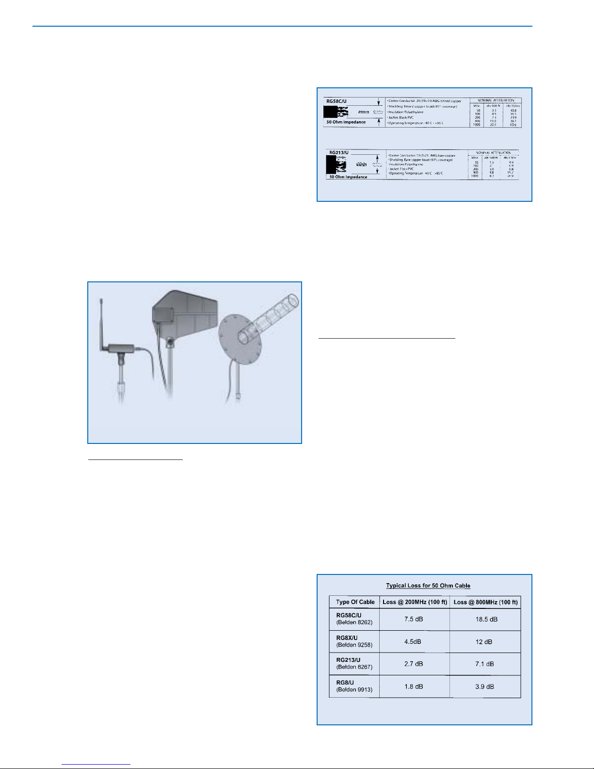
ANTENNA CABLE
An important but often overlooked component of many
wireless microphone systems is the antenna cable.
Applications in which the receiver is located away from the
transmitter vicinity and/or within metal racks will require the use
of remote antennas and connecting cables. Compared to
audio frequency signals, the nature of radio frequency signal
propagation in cables is such that significant losses can occur
in relatively short lengths of cable. The loss is a function of the
cable type and the frequency of the signal. Figures 2-28 and
2-29 give some approximate losses for various commonly
used antenna cables at different radio frequencies. It may be
noted from this chart that these cables have a "characteristic"
impedance, typically 50 ohms. Ideally , for minimum signal loss
in antenna systems, all components should have the same
impedance: that is the antennas, cables, connectors and the
inputs of the receivers. In practice, the actual losses due to
impedance mismatches in wireless receiver antenna systems
are negligible compared to the losses due to antenna cable
length. Obviously, the benefits of even a high gain antenna
can be quickly lost using the wrong cable or too long a cable.
In general, antenna cable lengths should be kept as short as
possible. Antenna amplifiers can be used to compensate for
losses in long cable runs. (See Figure 2-33.)
In addition, the construction of the cable should be
considered: coaxial cables with a solid center conductor and
stiff insulator/shield are most suitable for permanent installation,
while cables with stranded conductors and flexible insulator/
shield should be used for portable applications which require
repeated setups. Finally, the number of connections in the
antenna signal path should be kept to a minimum.
ANTENNA DISTRIBUTION
The last component found in larger wireless receiver
systems is some form of antenna signal distribution. It is often
desirable to reduce the total number of antennas in multiple
systems by distributing the signal from one set of antennas to
several receivers. This is usually done to simplify system setup,
but can also improve performance by reducing certain types of
interference as will be seen later . There are two general types of
antenna distribution available: passive and active. Passive
antenna splitting is accomplished with simple in-line devices that
provide RF impedance matching for minimum loss. Still, a
single passive split results in about a 3 dB loss, which may
translate into some loss of range. (See Figure 2-31.) Multiple
passive splits are impractical due to excessive signal loss.
To allow coupling of antenna signals to more receivers
and to overcome the loss of passive splitters, active antenna
distribution amplifiers are used. These are also known as "active
antenna splitters" or "antenna multi-couplers." These devices
provide enough amplification to make up for splitter loss, they
Selection
and Operation
of Wireless Microphone Systems
20
C HAPTER 2
Basic Radio Systems
Figure 2-27: examples of remote receiver antennas
Figure 2-29: coaxial antenna cable loss
at VHF and UHF frequencies
Figure 2-28: comparison of coaxial cable types
1/2 wave
(with amplifier)
log
periodic
helical
 Loading...