

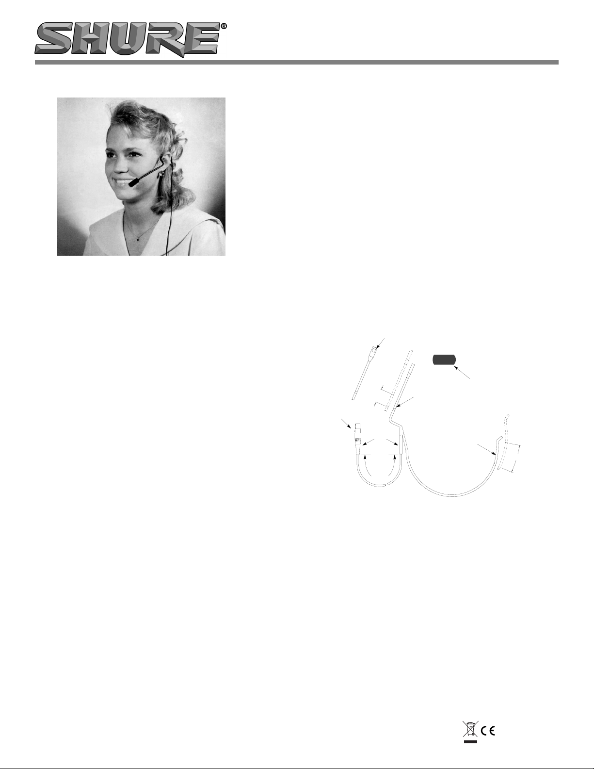
1.5 M
(5 FT)
POP SCREEN
CARTRIDGE
ADJUSTABLE
HEADBAND
ADJUSTABLE
BOOM
12.7 MM
(1/2 IN.)
57.2 MM
(2-1/4 IN.)
CABLE
TA4F
CONNECTOR
MODEL WCM16 ISOMAX* HEAD-WORN CONDENSER MICROPHONE
GENERAL
The Shure Model WCM16 head-worn electret condenser
microphone is intended for wireless use by performers, lecturers, and others who require the highest quality voice pickup with maximum mobility. Its wide frequency response, low
RF susceptibility and reliable operation at temperature and
humidity extremes make the WCM16 suitable for virtually
any vocal application. When used with the Shure Body-Pack
Transmitters, the performance of the WCM16 closely resembles the finest conventional vocal microphones.
Miniaturized active circuitry included in the cartridge assembly provides equalization that tailors the low-frequency
response to resemble the warm proximity effect of larger vocal microphones. Because of this low-end response, it is not
necessary to position the microphone directly in front of the
mouth, thus avoiding much popping and breath noise, even
without the supplied foam pop screen.
The microphone's hypercardioid unidirectional pickup
pattern provides maximum isolation from ambient noise and
from adjacent sound sources such as musical instruments,
loudspeakers and other performers. This permits higher
gain-before-feedback without loss or masking of vocals.
FEATURES:
• Extra lightweight, adjustable headband stays secure
and virtually disappears while being worn
• Response comparable to the finest conventional vocal
microphones
• Hypercardioid polar pattern provides maximum isola-
tion from vocalist's own instrument and those of other
performers
• Uniform polar pattern at all frequencies for maximum
• High input clipping level eliminates overload distortion
• Supplied acoustic foam pop screen
• Reliable at temperature and humidity extremes
27D2631 (Rev.6)
gain before feedback
*WCM16 is manufactured by Countryman Associates
ISOMAX is a trademark of Countryman Associates
Model WCM16 User Guide
WEARING THE MICROPHONE HEADSET
1. Place the microphone on the user's head so that the
large diameter band is horizontal across the back of the
head. The band may be completely hidden under the
hair. The ends of the headband should fit comfortably
in front of the ears. Extend or retract the adjustable
headband (see Figure 1) to achieve this result.
2. For maximum gain before feedback, carefully extend or
retract the boom (see Figure 1) so that the microphone
grille (silver side) is within 40 mm (1-1/2 in.) of the left
corner of the mouth. It may be necessary to bend the
headband tube just in front of the left ear for optimum
microphone positioning. A slight bend downward and/
or away is usually sufficient.
NOTE: The headband tubing will not withstand
repeated bending, so make this adjustment only once,
if necessary.
3. If breath noise or popping is audible, install the supplied pop screen so that the red dot on the pop screen
corresponds to the location of the microphone grille.
PARTS OF THE WCM16 HEAD-WORN MICROPHONE
FIGURE 1
POSITIONING THE MICROPHONE PICKUP
The hypercardioid unidirectional pickup pattern of the
WCM16 has maximum rejection of unwanted sound sources at about a 110° angle each way from the front axis of the
microphone (see Figure 1). Directly to the rear of the microphone (at 180°) there is as little as 6dB rejection-not much
less pickup than at the front of the microphone (at 0°).
Sound sources that may cause feedback (such as monitor or P.A. speakers) or sound that you do not want to pick
up with the WCM16 (such as percussion instruments or other performers) should NOT be placed directly to the rear of
the microphone. It is better to adjust positioning so that unwanted sound sources are located at the 110° maximum rejection points. Note that when wearing the headset the rear
of the microphone points out towards the wearer's left.
Printed in U.S.A.©2006 Shure Incorporated
CONNECTING TO A TRANSMITTER
1
3
4
2
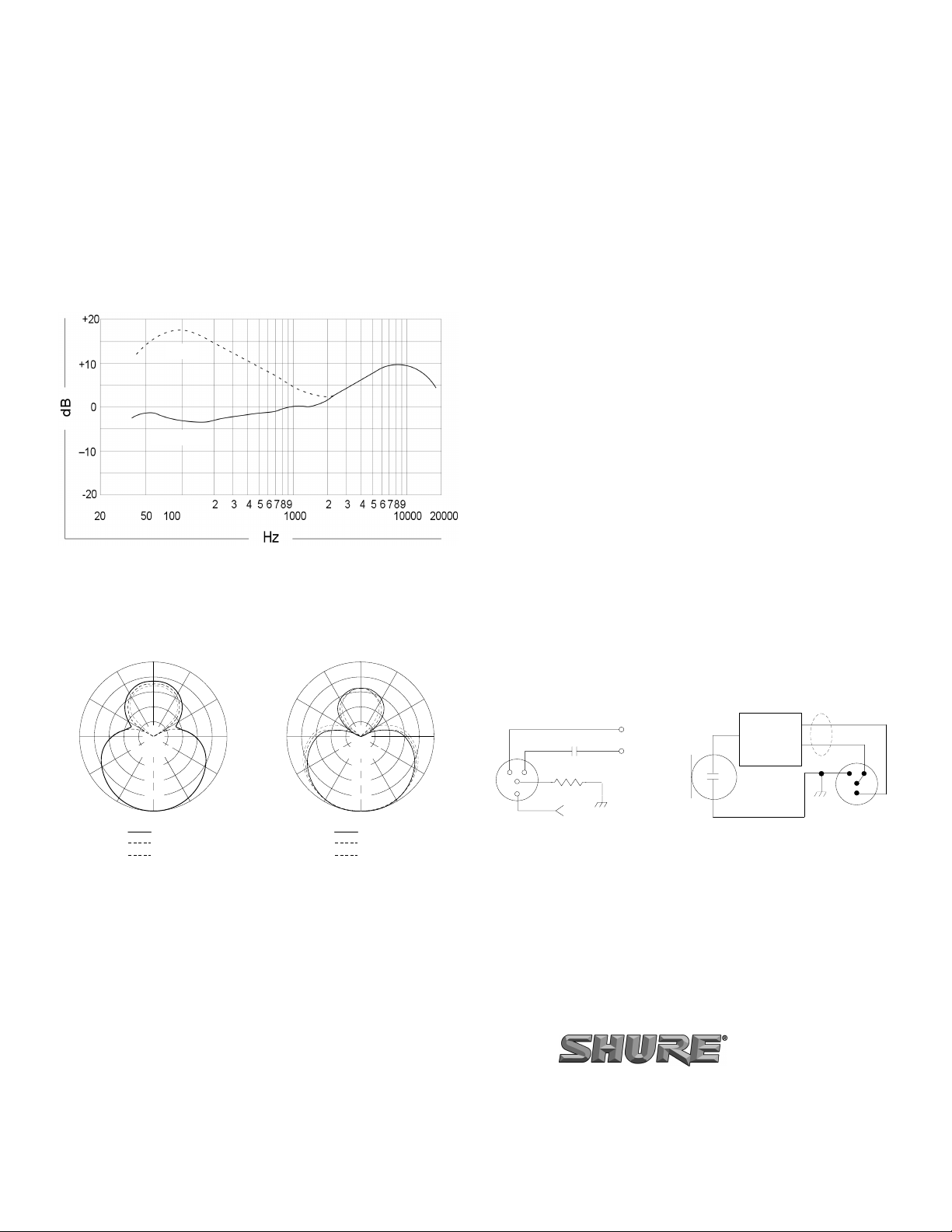
20 K
+5 V
V
OUT
SPECIFICATIONS TEST CIRCUIT
1
3
4
2
RESPONSE
SHAPING
CIRCUIT
MICROPHONE INTERNAL CONNECTIONS
RED
WHITE
SHIELD
The WCM16 is configured for direct connection to a
Shure Body-Pack Transmitter, such as models T1, T1G,
T11, SC1, EC1, or LX1, using the attached cable.
MICROPHONE POWERING
The WCM16 is designed to be powered from the +5 Vdc
source at microphone connector pin 2 of a Shure transmitter.
SPECIFICATIONS (Measured using test circuit in Figure 4)
Type
Condenser (electret bias)
Frequency Response
50 to 18,000 Hz
1 cm
0.6 m (2 ft.)
TYPICAL FREQUENCY RESPONSE
FIGURE 2
Polar Pattern
Hypercardioid, uniform with frequency
120
o
180
o
150
o
150
o
o
120
120
o
150
o
180
o
o
150
o
120
Output Level (close-talked at 1,000 Hz)
Open Circuit Voltage
-55.0 dbV (1.8 mV) at 0.6 m
1 Pascal=94 db SPL
Maximum Sound Pressure Level
150 dB at 1% THD
Dynamic Range
121 dB
Output Noise
29 dB equivalent SPL, A-weighted
Signal-to-Noise Ratio
65 dB at 94 dB SPL
Polarity
Microphone: Positive sound pressure on diaphragm produces
positive voltage on pins 3 and 4 with respect to pin 1 (ground) of
microphone output connector
Receiver—1/4" Phone Jack Output: Positive sound pressure on
diaphragm produces positive voltage on tip of receiver 1/4" output
connector
Receiver—XLR Output: Positive sound pressure on diaphragm
produces positive voltage on pin 2 with respect to pin 3 of the XLR
output connector
Current Drain
0.35 mA
Recommended Operating Voltage
+5 Vdc (positive on pin 2, negative on pin 1)
Environmental Conditions
Operating Temperatures: -18o to 60oC (0o to 140oF)
Storage Temperatures: -29
Humidity: 0 to 95%
o
to 66oC (-20o to 150oF)
Cable
1.5m (5 ft), small-diameter, shielded, with 4-pin mini connector
Case Finish (Microphone and Headband)
Matte black enamel
Net Weight
36 g (1.27 oz)
o
90
–
o
60
–
–
–
o
30
Output Impedance
1200 ohms
o
90
20 dB
15 dB
10 dB
5dB
0
250 Hz
500 Hz
1000 Hz
o
60
o
30
TYPICAL POLAR PATTERNS
FIGURE 3
o
90
–
20 dB
–
o
60
15 dB
–
10 dB
5dB
–
o
30
0
2500 Hz
6300 Hz
10000 Hz
o
30
o
90
o
60
TEST CIRCUIT AND WIRING
FIGURE 4
REPLACEMENT PARTS
Cable Connector...............................................................WA330
Windscreen...................................................................... 36A624
SHURE Incorporated http://www.shure.com
United States, Canada, Latin America, Caribbean:
5800 W. Touhy Avenue, Niles, IL 60714-4608, U.S.A.
Phone: 847-600-2000 U.S. Fax: 847-600-1212 Intl Fax: 847-600-6446
Europe, Middle East, Africa:
Shure Europe GmbH, Phone: 49-7131-72140 Fax: 49-7131-721414
Asia, Pacific:
Shure Asia Limited, Phone: 852-2893-4290 Fax: 852-2893-4055
 Loading...