

Page 1
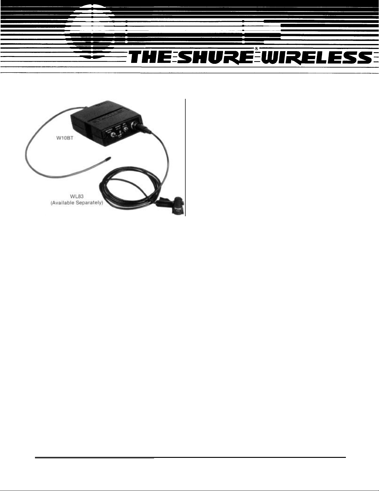
MODEL W10BT TRANSMITTER
The Shure Model W10BT is a body-pack radio
transmitter for use in the Shure Wireless Microphone
System. Small, compact and lightweight, the W10BT is
human-engineered for reliable, unobtrusive operation.
The microphone connector and all operating controls
are located on the upper surface, and the controls are
differentiated in size and shape to minimize incorrect or
accidental movement. (The gain control is generally
only used in setup, and is therefore recessed on the rear
panel.) A rugged belt clip provides secure attachment to
a belt, pocket or waistband. The antenna, a short piece
of thin, highly flexible wire, is an optimum choice for
minimum visibility and maximum durability.
The W10BT uses a standard 9-volt transistor-radiotype battery (alkaline recommended). This long-life battery is available everywhere, and replacement is easily
accomplished through a locking slide-off cover plate; no
screws or hinges are used. A battery test switch and
LED indicator provides information on battery condi-
tion.
The transmitter operates at a single, crystal-
controlled frequency in the VHF-FM band between 150
and 216 MHz. A total of 15 frequencies, computerselected for interference-free operation, are readily
available, and other frequencies can be ordered on a
special basis. This means that a number of wireless
microphone systems can be operated in a single sound
installation, simultaneously and without intermodulation problems.
The W10BT has a maximum output power of 50
milliwatts, based on Federal Communications Commission regulations. This means that the transmitter-toreceiver-antenna distance should be kept as short as
possible, with about 150 meters (500 feet) considered a
maximum. Operation at greater distances -300 meters
(1,000 feet) or more-is often accomplished, but the
determining factors in each installation will be reflections, obstacles and interference.
The transmitter is supplied with a zippered carrying
storage bag and a small screwdriver for adjusting the
transmitter gain.
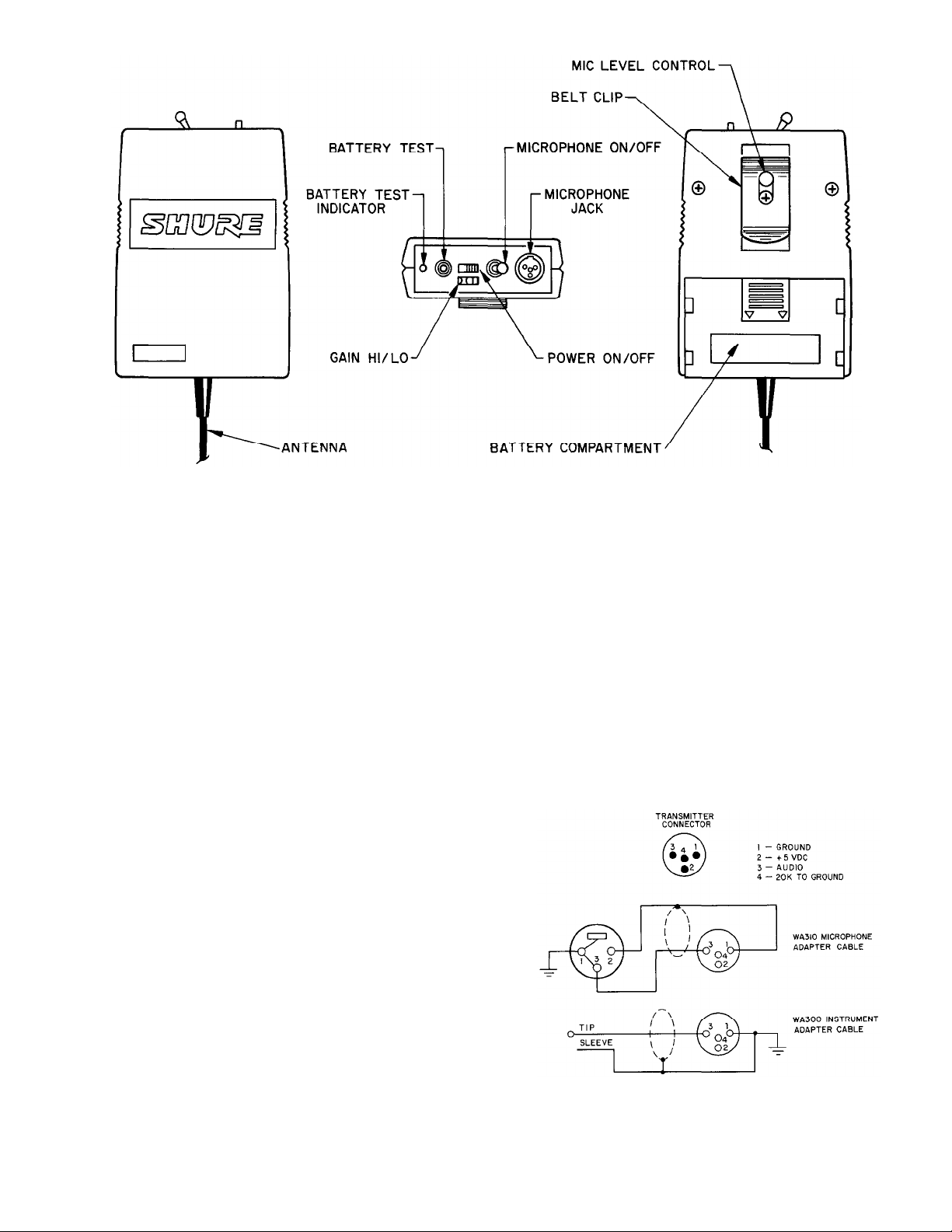
DESCRIPTION (see Figure 1)
ANTENNA: This is a flexible, 1/4-wave vertically
polarized antenna approximately 30 cm (12 in.) in length
and permanently attached to the bottom surface of the
transmitter. For proper operation, the antenna must be
in the vertical position, not coiled or bundled.
BATTERY (not supplied): Only alkaline (Duracell
MN1604 or equivalent) or heavy-duty nickel-cadmium
(8.4-volt) transistor-radio-type batteries should be used.
A fresh alkaline battery should provide approximately 8
hours of operation, and a fully charged nicad should provide 1-1/2 to 2 hours.
BATTERY COMPARTMENT: Slide-off cover exposes
the battery compartment.
BATTERY TEST Push-Button Switch: Permits checking
the condition of the installed battery when the power
switch is on. The Battery Test LED Indicator will fail to
light if the battery is weak or dead (or if the Power switch
is off). Note that if the battery is tested periodically during
an impending battery failure can be
use,
detected: the LED will fail to light at 7.25 volts. At that
time, approximately 1 hour of battery life remains
(alkaline batteries only).
BELT CLIP: Permits convenient attachment to the
user’s belt, waistband or other clothing.
GAIN HI/LO Slide Switch: Selects the High Gain position to boost the signal of low-output (low-impedance)
microphones, or the Low Gain position for high-output
(high-impedance) microphones or musical instruments.
Allows maximum modulation without clipping.
MICROPHONE JACK: This is a 4-pin, miniature, male
Tini Q-G connector designed to mate with Switchcraft
TA4F or equivalent connectors. A built-in 20-kilohm load
resistor provides proper matching for dynamic, ribbon or
condenser microphones. Connector pin 2 supplies
+5-volt bias voltage for condenser microphone phantom powering. In addition to microphones with TA4F
connectors, Shure has available an adapter cable with a
standard XLR female connector for use with conventional microphones (WA310), and a musical instrument
222 HARTREY AVENUE, EVANSTON, ILLINOIS 60202-3696 U.S.A.
Copyright 1986, Shure Brothers Inc.
27A2313 (FH)
l TELEPHONE: (312)866-2200 l CABLE: SHUREMlCRO
Printed in U.S.A.
Page 2
W10BT TRANSMITTER
FIGURE 1
adapter cable with a 1/4-in. phone plug on the equipment
end (WA300).
MICROPHONE LEVEL Rotary Control: In conjunction
with the Gain Hi/Lo switch, this control provides additional audio level adjustment. A small screwdriver is
supplied to make adjustments.
MICROPHONE ON/OFF Toggle Switch: Permits the
user to “mute” the microphone without turning the
transmitter off. This avoids the “pop” that may accompany power turn-on and turn-off, and generally prevents
pickup of unwanted signals by the receiver.
POWER ON/OFF Slide Switch: Applies power to the
transmitter circuitry. The switch is a low-profile type to
minimize accidental turn-off.
SETUP AND CONNECTIONS
With the transmitter POWER ON/OFF Switch in the
OFF position, slide the battery compartment access
cover down and off the transmitter case. Insert a new
9-volt transistor-radio-type battery (Duracell MN1604 or
equivalent) in the compartment. Observe the proper
polarity: the large (negative) terminal in the large channel and the small (positive) terminal in the small channel.
Operation with a full charged, heavy-duty, 8.4-volt nickelcadmium rechargeable battery is also permissible.
IMPORTANT: Do not use a “conventional” g-volt-sized
nickel-cadmium battery; its 7.2-volt output will operate
the transmitter for about 15 minutes. Carbon-zinc batteries will also result in diminished operating life (about
1 hour).
Microphone Connections
The Shure WL83 lavalier condenser microphone or
similar microphones with identical wiring and a Switch-
craft TA4F type connector can be plugged directly into
the transmitter microphone jack. The WL83 will operate
using the transmitter’s regulated +5 Vdc available on
pin 2 (see Figure 2). Self-powered (battery) condenser
microphones can be used with the transmitter on/y if
they can be operated in an unbalanced mode (one side
grounded). Other non-self-powered condenser
microphones may require special wiring; contact
Shure’s Service Department for further information.
Phantom-powered condenser microphones will not
operate with the W10BT.
A high- or low-impedance dynamic or ribbon
microphone with pin 2 output can be directly connected
to the transmitter using the supplied WA310 microphone
adapter cable. The cable has a 3-socket XLR connector
TRANSMITTER CONNECTIONS AND
ACCESSORY WIRING
FIGURE 2
2
Page 3

on the microphone end and a Switchcraft TA4F connector on the transmitter end, and is wired for unbalanced
low-impedance operation only (see Figure 2). Shure highimpedance microphones are not wired to operate with
the transmitter. If a Shure high-impedance microphone
must be used, pins 2 and 3 should be reversed (by
qualified service personnel). Using a low-output, lowimpedance dynamic lavalier microphone such as
Shure’s SM11 may require raising the mixer input gain
appreciably, which in turn may result in an increase in
noise and signal “pumping.”
Instrument Connections
To connect the transmitter to a guitar or other musical
instrument pickup, obtain an instrument adapter cable
such as Shure’s WA300. This cable has a 1/4-inch phone
plug on one end and a Switchcraft TA4F on the other
(see Figure 2) and should function normally with any
high-impedance instrument pickup.
Battery Check
Turn the transmitter power on and depress the BAT-
TERY TEST Switch. The adjacent LED should light, indicating adequate transmitter input voltage. If the LED
does not light, the battery voltage has dropped below
7.25 volts and the battery should be replaced or recharged (nicad only).
If the battery is tested periodically, the failure of the
LED to light indicates approximately one hour of battery
life left (alkaline only).
AUDIO LEVEL DISPLAY
FIGURE 3
High. For high sound pressure level (SPL) applications
such as loud singing or musical instruments, the preset
transmitter level may be too high. To avoid this overload
and potential distortion condition, use the supplied
screwdriver to turn the transmitter MIC LEVEL Control
down (counterclockwise; see Figure 4). This adjustment
should be made under the expected operating conditions, that is, with the high SPL singer or musical instrument in use at the microphone. Turn the control down
until the optimum (-7 to 0) readings are obtained.
SETTING GAIN LEVEL
Place the POWER Switch of the receiver in the ON
position. The green POWER LED will light.
Turn the transmitter POWER ON/OFF Switch on.
Observe the receiver RF SIGNAL LEVEL indicator. With
Shure W20R receivers, the signal yellow LED should be
continually lit, indicating adequate RF signal strength
for good transmission. If the LED continually flickers or
does not light, consult the Troubleshooting section of
the receiver manual.
With Shure W25DR receivers, one of the green LED
segments should light, indicating adequate RF signal
strength for good transmission. A yellow LED indication
means less than optimum signal transmission and/or
reception, and a red LED indicates less than satisfactory
operation.
Turn the transmitter MIC ON/OFF Switch to the ON
position. With a microphone connected to the transmitter, the receiver audio level display will now respond to
varying sound levels.
SET the transmitter GAIN Switch as dictated by the
type of input: HI for low-impedance microphones; LO
for high-impedance microphones and instrument
pickups.
Sound Pressure Levels
Normal. The transmitter MIC LEVEL Control has been
factory-set to provide optimum audio modulation at the
receiver, as indicated by LED illumination in the -7 to 0
range (see Figure 3). Readings in this area will yield the
highest dynamic range without overload and resulting
distortion.
HIGH SPL GAIN ADJUSTMENT
FIGURE 4
Low. Low SPL applications such as soft-spoken in-
dividuals or conditions where the microphone must be at
a greater-than-normal distance from the sound source,
may require an increase in the transmitter gain setting.
To correct for a low-level condition, turn the MIC LEVEL
Control up (clockwise; see Figure 5) until a proper (-7 to
0) LED reading is obtained.
LOW SPL GAIN ADJUSTMENT
FIGURE 5
3
Page 4

RECEIVER GAIN
The rear-panel receiver OUTPUT can be adjusted using
the MICROPHONE OUTPUT LEVEL Control. In this way,
the wireless system output can be made identical to that
of a conventional wired microphone, avoiding extreme
differences in input level settings. Turning the
MICROPHONE OUTPUT LEVEL Control counterclockwise decreases the output level, and turning it
clockwise increases the output.
OPERATION
1.
Turn on the transmitter and receiver POWER
Switches.
2.
Make sure the transmitter MIC ON/OFF Switch is on.
3. Talk into the microphone (or play the connected
musical instrument) and observe the receiver display
for proper audio and RF indications.
4.
Continue talking or playing and move around the performing area. In each area, observe the receiver
displays and make sure the RF signal strength is
adequate.
Normal operation is shown by steady illumination of
the green RF SIGNAL LED on the Shure W20R receiver,
or by illumination of at least one green LED of the RF
SIGNAL LEVEL display on the W25DR receiver. Weak
signals are evidenced by intermittent operation of the
W20R LED and by illumination of the lower LEDs on the
W25DR.
In most cases, the problem of weak RF signal strength
is also indicated by audible evidence:
either continuous or intermittent, or noisy, distorted
operation. The condition is generally caused by poor
antenna location, RF signal blocking, or operation
beyond the system capability. Refer to the
Troubleshooting section of the receiver manual for
remedies.
Feedback-the annoying howl or squeal heard in the
sound system- is as much a problem in wireless
microphones as in wired mics. Checking microphone
operation throughout the performing area will probably
uncover any locations that are prone to audio feedback.
If the problem cannot be solved by a slight lowering of
the receiver output level or the associated amplifier gain,
relocation of the speakers or possibly professional
equalization of the sound system is recommended.
signal dropout,
IMPORTANT
Every wireless microphone installation is a unique
situation, and can present a variety of problems.
Never attempt a live performance without a
“walkthrough” first. And if major changes (furniture, scenery, etc.) were made since the
walkthrough,
operation again.
check the wireless microphone
SPECIFICATIONS
RF Power Output
50 mW maximum; 30 mW typical
Modulation
54F3 ± 12 kHz deviation, 50 µsec pre-emphasis
Modulation Limiter
Internal compressor
Input Impedance
Actual: 16k (20k dc), pin 4 wired to pin 3 for WL83
microphone; 91k, pin 4 open for microphone or instru-
ment pickup
Gain Switch
High position . . . . . . . 0.0065 Vrms required for
100% modulation
Low position . . . . . . . . . 0.065 Vrms required for
100% modulation
Gain Adjustment Range
Low Position . . . . . . . . . . . . . . . . . . . . . . 20 dB
High Position . . . . . . . . . . . . . . . . . . . . . . . 30 dB
Antenna
Attached, 305 mm (12 in.), omnidirectional, flexible
wire
Power
Battery Type . . . . . . . 9-volt alkaline (NEDA
1604A); 8.4-volt nicad optional
Battery Life . . . . . . . . . .
Current Drain . . . . . . . . 35 mA typical
6 to 8 hours typical
(alkaline); 1.5 to 2 hours
typical (8.4-volt nicad; per
charge)
Dimensions
102 mm H x 69.8 mm W x 25.4 mm D (4 in. x 2-3/4 in. x 1
in.) (not including antenna, controls and belt clip)
Weight
113 grams (4 oz); 170 grams (6 oz) with battery
ANTENNA
The transmitter antenna is a permanently attached,
flexible wire, 1/4-wave antenna. It has an omnidirectional
pickup pattern (equally effective in all directions) and is
designed to operate in a vertically polarized mode. This
means that the antenna should hang downward during
operation; coiling or wadding it to minimize visibility will
reduce the system’s operating distance.
BATTERIES
Careful transmitter battery selection, installation, use
and care will help avoid problems in wireless
microphone use. The most dependable, long-lived batteries at this time are the manganese-alkaline, or
alkaline, types. In addition to offering the longest expected operating life, they are commonly available.
One small word of caution about alkaline batteries:
they are not all the same size. Make certain the battery
you buy will make contact inside the battery compartment.
Nickel-cadmium (nicad) batteries can save money
through their rechargeability, but the tradeoff is in
shorter expected life per charge. In addition, forgetting
to recharge can be disastrous.
Another major consideration in nicads is that of
operating voltage. The “heavy-duty” 8.4-volt nicads are
satisfactory for transmitter use, but the “9-volt-size”
nicads commonly found in stores are only 7.2 volts and
will not provide satisfactory wireless performance.
4
Page 5

Mercury batteries in the “9-volt-size” are also actually
8.4 volts. However, their discharge characteristics are
such that they will yield between 10 and 15 hours of
operation with the transmitter.
Carbon-zinc batteries are the least useful for transmitter operation. Their low cost is more than offset by their
extremely short operating and shelf life. Although the
“heavy-duty” (HD) carbon-zinc types offer better lowtemperature performance and service capacity at
moderate to high current drain, they will not offer appreciably better transmitter performance than standard
carbon-zinc batteries.
Although battery operation is inhibited at low
temperatures, storing batteries at low temperatures will
increase their shelf life. They should be sealed in bags
and, when ready for use, allowed to warm up to room
temperature (never heated!). Cold-stored batteries
should be used as soon as possible after bringing to
room temperature.
Battery life is shortened by high-temperature storage
such as on amplifiers or in vehicles exposed to direct
sunlight.
RECOMMENDED RANGES
Alkaline
Temperature
Shelf Life (room 30 months
temperature; to
80% of capacity)
0° to 38°C
(32° to 100°F) (40° to 130°F) (45° to 90°F) (-4° to 113°F)
Mercury Zinc
4° to 54°C 7° to 32°C
30 months 6 to 12 10 to 80 days
Carbon-
months
Nicad
-20° to 45°C
The battery should be removed if the transmitter
malfunctions, or if it is to be stored for a long period.
Most batteries have a protective jacket, but partly or
completely exhausted batteries are more prone to
leakage.
Do not attempt to recharge replaceable (primary) bat-
teries using “chargers”, heat or other methods. This may
cause leakage or explosion. Do not disassemble batteries or dispose of them in fire.
BATTERY TYPE
Alkaline
Mercury
Nickel-Cadmium
MANUFACTURER
& NO.
Bright Star 7590
Duracell MN1604
ESB A1604
Eveready 522
IEC 6LF22
NEDA 1604A
Panasonic 6AM6
Radio Shack
23-553
Ray-0-Vac A1604
US. Military
BA3090
Varta 4022
Burgess H146X
Duracell TR146X
Eveready E146X
NEDA 1604M
Panasonic TR146
U.S. Military
BA1090/U
SAFT PS-9
Varta TR7/8
VOLTS
9.0
8.4
8.4
EXPECTED LIFE
6 to 7 hours
10 to 15 hours
1-1/2 to 2 hours
per charge
Carbon-Zinc Duracell M1604
Carbon-Zinc
(Heavy Duty)
Eveready 216
Ray-0-Vac 1604
Radio Shack
23-464
Duracell
M1604HD
Eveready 1222
Ray-0-Vac D1604
Radio Shack
23-583
9.0
9.0
1 hour
1 hour
ACCESSORIES
The following Shure transmitter accessories are
available through your Shure dealer. (Replacement parts
can be ordered from Shure’s Service Department; information is available from Shure’s Service Department.)
MODEL WL83 LAVALIER CONDENSER MICROPHONE
- This is a tiny electret condenser microphone designed for high-quality sound reproduction in broadcasting,
film and sound reinforcement applications. The WL83
plugs directly into the W10BT transmitter, and is supplied with a variety of mounting options.
MODEL WA300 INSTRUMENT CABLE - This is a 1.2m (4
ft), single-conductor, shielded cable with a 1/4-inch
phone plug on one end and a Switchcraft TA4F on the
other. It is used for connecting the W10BT transmitter to
a guitar or other musical instrument pickup.
MODEL WA310 MICROPHONE CABLE - A 1.2m (4 ft),
single-conductor, shielded cable with a 3-socket (female)
XLR connector on one end and a Switchcraft TA4F on
the other. The WA310 is designed to connect the W10BT
to a low-impedance dynamic or condenser microphone
for unbalanced operation.
MODEL WA330 MICROPHONE CONNECTOR - This
TA4F miniature connector permits microphones such as
the Shure SM10A or SM98 to be connected directly to the
W10BT transmitter.
FCC CERTIFICATION
The Shure Model W10BT transmitter is Type-Accepted
under Federal Communications Commission Parts 90
and 74. Licensing of Shure wireless microphone equip-
ment is the user’s responsibility, and licensability
depends on the user’s classification and application,
and on the selected frequency. Shure strongly urges the
user to contact the appropriate telecommunications
authority before choosing and ordering frequencies
other than factory-preset frequencies. This recommendation applies to both original equipment purchase and
subsequent frequency modification by Shure.
WARRANTY SERVICE
If your Shure wireless microphone equipment should
require servicing under the Shure warranty, please contact:
Shure Brothers Inc.
Attention: Service Department
222 Hartrey Avenue
Evanston, Illinois 60202-3696 U.S.A.
Telephone: (312) 866-5730
Refer to receiver manual for details on warranty service.
5
 Loading...