

ST3500
Teleconferencing System
Installer's Guide
TABLE
OF CONTENTS
PRODUCT DESCRIPTION
MAJOR FEATURES
SYSTEM COMPONENTS
SYSTEM FEATURES
DigiMix Microphone Selection
Adaptive Echo Cancellation
Expansioncapabilities
ACOUSTIC MODULE CONTROLS AND INDICATORS
USER SELECTABLE PARAMETERS
TELEPHONE INTERFACE BOX CONNECTORS
TELEPHONE INTERFACE BOX MOUNTING
Horizontal (Floor) Mounting
Vertical (Wall) Mounting
SINGLE ACOUSTIC MODULE PLACEMENT
BASIC SYSTEM INSTALLATION
EXPANSION MODULE PLACEMENT
EXPANDED SYSTEM INSTALLATION
OPERATING THE SYSTEM
Placing a Call
Answering a Call
Using the Mute Function
Using the Flash Function
Switching to Tone Dialing in Pulse Mode
Hangingup
Using the Automatic Redial Function
PREVENTIVE MAINTENANCE
TROUBLESHOOTING
SPECIFICATIONS
TELEPHONEINTERFACE
REPLACEMENTPARTS
ACCESSORIES
SERVICEANDREPAIRS
FCCREQUIREMENTS
APPENDIX
APPENDIX
........................................................
.....................................................
.........................................................
...................................................
I:
WHAT IS DlGlMlX AND WHAT DOES IT DO?
II:
ST3500 FEATURES AND BENEFITS
..........................................
................................................
...........................................
...............................................
..........................................
............................................
................................................
.....................................
......................
..........................
............................................
...............................................
.........................
....................................
................................
...............................
.........................................
..............................................
..............................................
.................................
....................................
......................................
..............................................
.................................................
..........................................
............................................
...........................................
.............................................
.................
............
...................
2
2
2
2
2
3
3
4
5
6
6
6
7
8
9
10
11
12
12
12
13
14
14
14
15
15
16
17
18
18
19
19
19
20
22
WARNING:
NEVER install telephone wiring during a lightning storm
.
NEVER install telephone jacks in wet locations unless the jack
is specifically designed for wet locations
.
NEVER touch uninsulated telephone wires or terminals unless
the telephone line has been disconnected at the network interface
.
ALWAYS USE CAUTION when installing or modifying telephone
.
lines
PRODUCT DESCRIPTION
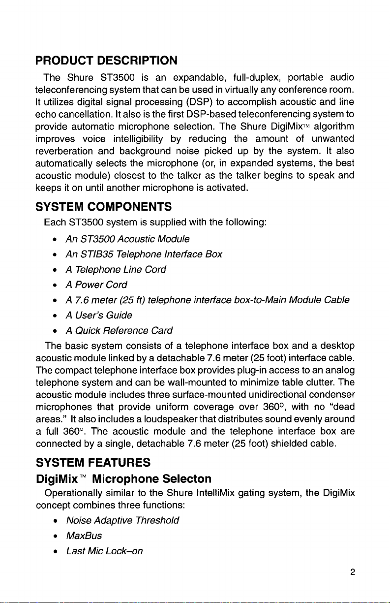
The Shure ST3500 is an expandable, full-duplex, portable audio
teleconferencing system that can be used in virtually any conference room.
It utilizes digital signal processing (DSP) to accomplish acoustic and line
echo cancellation. It also is the first DSP-based teleconferencing system to
provide automatic microphone selection. The Shure
improves voice intelligibility by reducing the amount of unwanted
reverberation and background noise picked up by the system. It also
automatically selects the microphone (or, in expanded systems, the best
acoustic module) closest to the talker as the talker begins to speak and
keeps it on until another microphone is activated.
DigiMix~~ algorithm
SYSTEM COMPONENTS
Each ST3500 system is supplied with the following:
An ST3500 Acoustic Module
An STIB35 Telephone Interface Box
A Telephone Line Cord
A Power Cord
A
7.6
meter (25 ft) telephone interface box-to-Main Module Cable
A User's Guide
A Quick Reference Card
The basic system consists of a telephone interface box and a desktop
acoustic module linked by a detachable 7.6 meter (25 foot) interface cable.
The compact telephone interface box provides plug-in access to an analog
telephone system and can be wall-mounted to minimize table clutter. The
acoustic module includes three surface-mounted unidirectional condenser
microphones that provide uniform coverage over
areas." It also includes a loudspeaker that distributes sound evenly around
a full
360". The acoustic module and the telephone interface box are
connected by a single, detachable 7.6 meter (25 foot) shielded cable.
360°, with no "dead
SYSTEM FEATURES
DigiMix" Microphone Selecton
Operationally similar to the Shure IntelliMix gating system, the DigiMix
concept combines three functions:
Noise Adaptive Threshold
MaxBus
Last Mic Lock-on
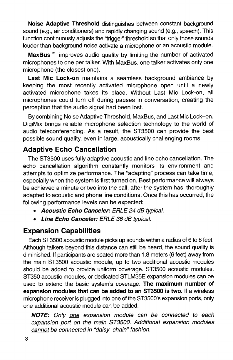
Noise Adaptive Threshold
(e.g., air conditioners) and rapidly changing sound (e.g., speech). This
sound
function continuously adjusts the "trigger" threshold so that only those sounds
louder than background noise activate a microphone or an acoustic module.
MaxBus"
microphones to one per talker. With MaxBus, one talker activates only one
microphone (the closest one).
Last Mic Lock-on
keeping the most recently activated microphone open until a newly
activated microphone takes its place. Without Last Mic Lock-on, all
microphones could turn off during pauses in conversation, creating the
perception that the audio signal had been lost.
By combining Noise Adaptive Threshold, MaxBus, and Last Mic Lock-on,
DigiMix brings reliable microphone selection technology to the world of
audio teleconferencing. As a result, the ST3500 can provide the best
possible sound quality, even in large, acoustically challenging rooms.
improves audio quality by limiting the number of activated
maintains a seamless background ambiance by
distinguishes between constant background
Adaptive Echo Cancellation
The ST3500 uses fully adaptive acoustic and line echo cancellation. The
echo cancellation algorithm constantly monitors its environment and
attempts to optimize performance. The "adapting" process can take time,
especially when the system is first turned on. Best performance will always
be achieved a minute or two into the call, after the system has thoroughly
adapted to acoustic and phone line conditions. Once this has occurred, the
following performance levels can be expected:
Acoustic Echo Canceler:
Line Echo Canceler:
ERLE
ERLE
24
36
dB typical.
dB typical.
Expansion Capabilities
Each ST3500 acoustic module picks up sounds within a radius of 6 to 8 feet.
Although talkers beyond this distance can still be heard, the sound quality is
If
diminished.
the main ST3500 acoustic module, up to two additional acoustic modules
should be added to provide uniform coverage. ST3500 acoustic modules,
ST350 acoustic modules, or dedicated
used to extend the basic system's coverage.
expansion modules that can be added to an ST3500 is
microphone receiver is plugged into one of the
one additional acoustic module can be added.
NOTE: Only one expansion module can be connected to each
expansion port on the main
cannot
3
participants are seated more than
STLM35E expansion modules can be
ST3500.
be
connected in "daisy+hainV fashion.
1.8
meters
The maximum number of
ST35003 expansion ports, only
Additional expansion modules
(6
feet) away from
two.
If a wireless
ACOUSTIC MODULE CONTROLS & INDICATORS
(Figure
1)
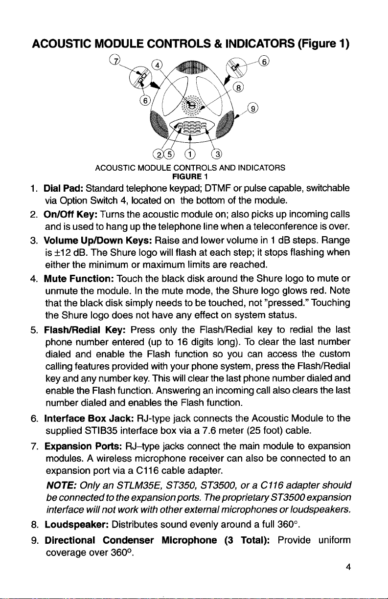
ACOUSTIC MODULE CONTROLS AND INDICATORS
FIGURE
1
1. Dial Pad: Standard telephone keypad; DTMF or pulse capable, switchable
4,
via Option Switch
2.
OnIOff Key: Turns the acoustic module on; also picks up incoming calls
located on the bottom of the module.
and is used to hang up the telephone line when a teleconference is over.
3. Volume
is
UpIDown Keys: Raise and lower volume in 1 dB steps. Range
+I
2
dB. The Shure logo will flash at each step; it stops flashing when
either the minimum or maximum limits are reached.
4.
Mute Function: Touch the black disk around the Shure logo to mute or
unmute the module. In the mute mode, the Shure logo glows red. Note
that the black disk simply needs to be touched, not "pressed." Touching
the Shure logo does not have any effect on system status.
FlashIRedial Key: Press only the FlashIRedial key to redial the last
5.
phone number entered (up to 16 digits long). To clear the last number
dialed and enable the Flash function so you can access the custom
calling features provided with your phone system, press the
FlashIRedial
key and any number key. This will clear the last phone number dialed and
enable the Flash function. Answering an incoming call also clears the last
number dialed and enables the Flash function.
6. Interface Box Jack: RJ-type jack connects the Acoustic Module to the
supplied
STIB35 interface box via a 7.6 meter
(25
foot) cable.
7. Expansion Ports: RJ-type jacks connect the main module to expansion
modules. A wireless microphone receiver can also be connected to an
expansion port via a C116 cable adapter.
NOTE:
Only an STLM35E, ST350, ST3500, or a
C
11
6
adapter should
be connected to the expansion ports. The proprietary ST3500 expansion
interface will not work with other external microphones or loudspeakers.
8.
Loudspeaker: Distributes sound evenly around a full 360".
9.
Directional Condenser Microphone
coverage over
360°.
(3
Total): Provide uniform
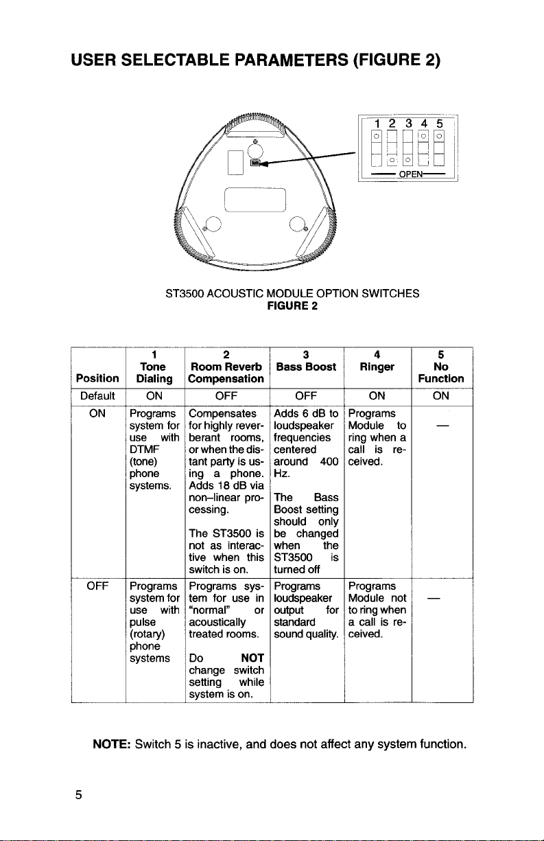
USER SELECTABLE PARAMETERS (FIGURE
2)
Position
Default
OFF
ST3500 ACOUSTIC MODULE OPTION SWITCHES
1
Tone
Dialing
ON
Programs Compensates
system for for highly rever-
7
DTMF with or berant when the rooms, dis(tone) tant party is us-
phone ing a phone.
systems. Adds
Programs Programs syssystem for tem for use in
pulse acoustically
(rotary) treated rooms.
phone
2
Room Reverb
Compensation
OFF
18
non-linear processing.
The ST3500 is
not as interactive when this
switch is on.
change switch
setting while
system is on.
dB via
FIGURE
2
3
Bass Boost
OFF
frequencies
centered
around 400
The Bass
Boost setting
should only
be changed
when the
ST3500 is
turned off
Programs
loudspeaker
output for
standard
sound quality.
4
Ringer
ON
Programs
Module to
ring when a
call is received.
Programs
Module not
to ring when
a call is received.
5
No
Function
ON
NOTE:
Switch 5 is inactive, and does not affect any system function.
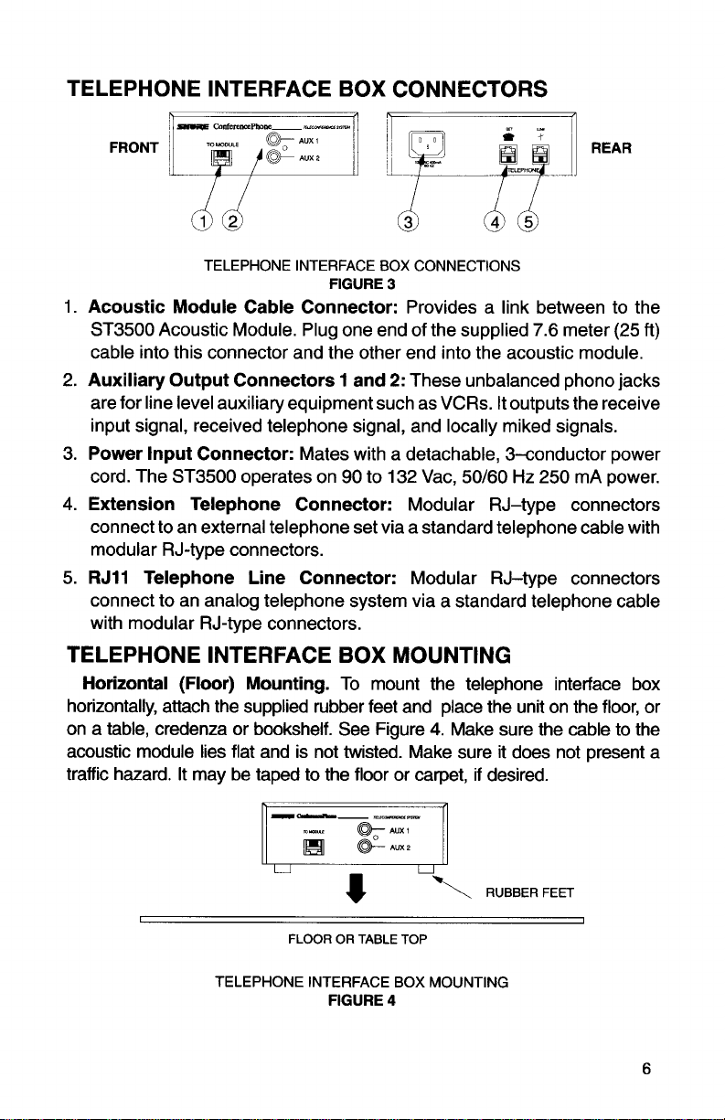
TELEPHONE INTERFACE BOX CONNECTORS
FRONT
TELEPHONE INTERFACE BOX CONNECTIONS
FIGURE
1.
Acoustic Module Cable Connector:
ST3500 Acoustic Module. Plug one end of the supplied 7.6 meter (25
cable into this connector and the other end into the acoustic module.
2.
Auxiliary Output Connectors 1 and
are for line level auxiliary equipment such as VCRs. It outputs the receive
input signal, received telephone signal, and locally miked signals.
Power Input Connector:
3.
Mates with a detachable, 3-conductor power
cord. The ST3500 operates on 90 to 132
4.
Extension Telephone Connector:
connect to an external telephone set via a standard telephone cable with
modular RJ-type connectors.
5.
RJ11
Telephone Line Connector:
connect to an analog telephone system via a standard telephone cable
with modular RJ-type connectors.
3
Provides a link between to the
2:
These unbalanced phono jacks
Vac, 50160
Hz
250 mA power.
Modular RJ-type connectors
Modular RJ-type connectors
ft)
TELEPHONE INTERFACE BOX MOUNTING
Horizontal (Floor) Mounting.
horizontally, attach the supplied rubber feet and place the unit on the floor, or
on a table, credenza or bookshelf. See Figure
acoustic module lies flat and is not twisted. Make sure it does not present a
traffic hazard. It may be taped to the floor or carpet, if desired.
u
I
TELEPHONE INTERFACE BOX MOUNTING
To mount the telephone interface box
4.
Make sure the cable to the
8
FLOOR OR TABLE TOP
FIGURE
4
-1\
RUBBERFEET
I
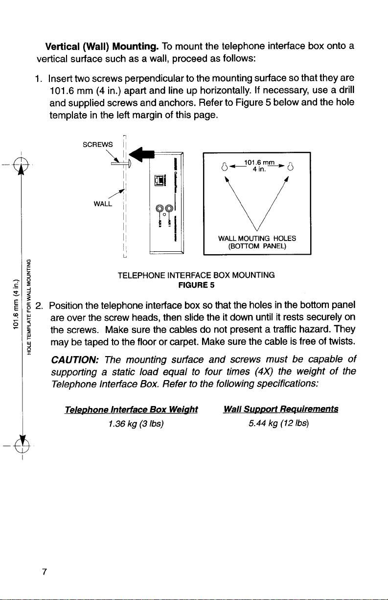
Vertical
vertical surface such as a wall, proceed as follows:
1.
Insert two screws perpendicular to the mounting surface so that they are
101.6
and supplied screws and anchors. Refer to Figure
template in the left margin of this page.
(Wall)
mm
Mounting.
(4
in.) apart and line up horizontally. If necessary, use a drill
To mount the telephone interface box onto a
5
below and the hole
SCREWS
11
0
do'&,m_m,
0
v
WALL
MOUTING
(BOTTOM
TELEPHONE INTERFACE BOX MOUNTING
3
g
2.
Position the telephone interface box so that the holes in the bottom panel
P
are over the screw heads, then slide the it down until it rests securely on
4
%
the screws. Make sure the cables do not present a traffic hazard. They
may be taped to the floor or carpet. Make sure the cable is free of twists.
Q
I
CAUTION:
supporting a static load equal to four times
Telephone lnterface Box. Refer to the following specifications:
Telephone Interface
The mounting surface and screws must be capable of
Box
1.36
kg
(3
Ibs)
FIGURE
Weiaht
5
Wall Support Requirements
(4X)
5.44
HOLES
PANEL)
the weight of the
kg
(12
Ibs)

SINGLE ACOUSTIC MODULE PLACEMENT
For best microphone coverage with a basic (single acoustic module)
ST3500
table. Conferees should be seated uniformly around the acoustic module
to minimize level differences in the pick-up of their voices. In noisier rooms,
talkers need to be seated closer to the module. Refer to Figure
determine optimum talker-to-module distance.
system, place the acoustic module in the center of the conference
6
to
MAX DISTANCE
FROM MlCS
MAX
NOISE
IN
FOR ST3500
NOTE:
ROOM
LEVELS
dBA
1.82
\
\V
Keep large sound-reflecting objects such as water carafes and
briefcases at least
_---
,
/
rn
(M
$
\
\55
\
\
'1
ACOUSTIC MODULE COVERAGE GUIDE
0.3
meters
\
\
.
-----
(1
'--
FIGURE
1
/
/
/
/
I
6
/@
/
/
/
foot) away from the acoustic module(s).
'
NOISE
MAX
ROOM
LEVELS
IN
dBA
FOR ST350

Y-
TELEPHONE
TELEPHONE
INTERFACE
LINE
BOX
\
3
BASIC SYSTEM CABLE CONNECTIONS
FIGURE
BASIC SYSTEM INSTALLATION
7
-
fl
do
P?
/
120
VAC
POWER
OUTLET
To install the basic ST3500 system for the first time, refer to Figure 7 and
proceed as follows:
1.
Connect an ST3500 acoustic module to the telephone interface box,
7.6
using the supplied black
connectors snap into place.
2. Connect one end of the gray telephone cable to the telephone line outlet
in the wall or floor, and connect the other end to the labeled Telephone
Line connector on the telephone interface box.
3.
Connect the female end of the power cord to the telephone interface box,
and plug the male end of the telephone interface box power cord into a 120
Vac, 60
Hz
electrical outlet. The system is now ready to use.
meter (25 foot) cable. Make sure the

EXPANSION MODULE PLACEMENT
To accommodate larger groups, use multiple ST3500 acoustic modules or
connect ST350 or optional
Refer to Figure
NOTE:
8.
STLM35E expansion modules are similar to ST350 acoustic
modules, but do not have a keypad or Option Switches.
STLM35E expansion modules to the main ST3500.
MAX. DISTANCE MAX. ROOM
FROM
MlCS NOISE LEVELS
MULTIPLE EXPANSION MODULE COVERAGE GUIDE
FIGURE
Each expansion module should be placed a maximum of 2.4 meters
8
(8
feet) and a minimum of 1.2 meters (4 feet) from the main acoustic module.
The distance between an expansion module and the main module should
be approximately three times the distance between a talker and the nearest
expansion module. Refer to Figure
TALKER
1
9.
TALKER
2
-1,-
MAX.
2.4
ST3500
ACOUSTIC MODULE
RECOMMENDED EXPANSION MODULE PLACEMENT
METERS
(8
FEET)
FIGURE
EXPANSION MODULE
9

EXTENSION TELEPHONE
TELEPHONE IN-
TERFACE BOX
WIRELESS RECEIVER
(OPTIONAL)
EXPANSION MODULE
EXPANDED SYSTEM CABLE CONNECTIONS
MAIN ST3500 ACOUSTIC EXPANSION MODULE
MODULE
FIGURE
10
EXPANDED SYSTEM INSTALLATION
To expand the ST3500 teleconferencing system to accommodate large
groups, refer to Figure 10 and proceed as follows:
1. Connect an ST3500 acoustic module to the telephone interface box,
using the supplied black 7.6 meter (25 foot) cable. Make sure the
connectors snap into place.
2. Connect one end of the gray telephone cable to the telephone line outlet
in the wall or floor, and connect the other end to the labeled Telephone
Line connector on the telephone interface box.
3. Connect the
ST3500 acoustic
acoustic module.
4.
If
an extension telephone is used, connect it to the Telephone Set
connector on the telephone interface box.
5.
Connect any auxiliary equipment, such as a tape recorder or a
the
AUX
6. Connect the female end of the power cord to the telephone interface box,
and plug the male end of the telephone interface box power cord into a 120
Vac, 60
STLM35E expansion module(s) or the additional ST350 or
module(s) to the expansion ports on the main ST3500
1
or
AUX
2
connectors on the telephone interface box.
Hz
electrical outlet.
VCR,
to
OPERATING THE SYSTEM
Placing a Call
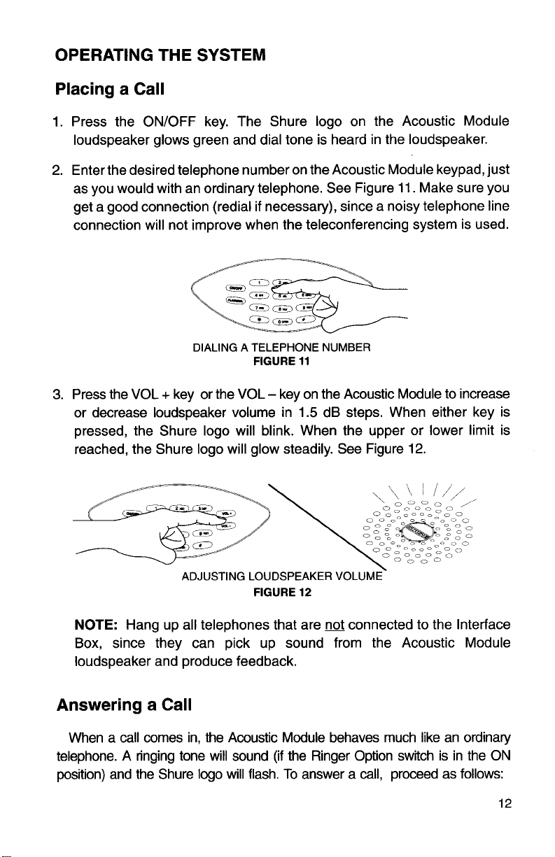
1.
Press the ONIOFF key. The Shure logo on the Acoustic Module
loudspeaker glows green and dial tone is heard in the loudspeaker.
2.
Enter the desired telephone number on the Acoustic Module keypad, just
as you would with an ordinary telephone. See Figure
get a good connection
(redial if necessary), since a noisy telephone line
connection will not improve when the teleconferencing system is used.
11.
Make sure you
DIALING A TELEPHONE NUMBER
FIGURE
11
3. Press the VOL + key or the VOL - key on the Acoustic Module to increase
or decrease loudspeaker volume in
1.5
dB steps. When either key is
pressed, the Shure logo will blink. When the upper or lower limit is
reached, the Shure logo will glow steadily. See Figure
ADJUSTING LOUDSPEAKER VOLUME
NOTE:
FIGURE
Hang up all telephones that are
12
not
connected to the Interface
12.
Box, since they can pick up sound from the Acoustic Module
loudspeaker and produce feedback.
Answering a Call
When a call comes in, the Acoustic Module behaves much like an ordinary
telephone. A ringing tone will sound (if the Ringer Option switch is in the ON
position) and the Shure logo will flash. To answer a call, proceed as follows:
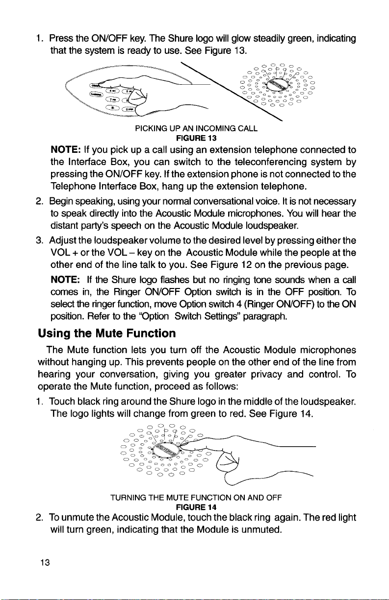
1. Press the ONIOFF key. The Shure logo will glow steadily green, indicating
that the system is ready to use. See Figure
13.
NOTE:
PICKING UP AN INCOMING CALL
If you pick up a call using an extension telephone connected to
FIGURE
13
the lnterface Box, you can switch to the teleconferencing system by
pressing the ONIOFF key. If the extension phone is not connected to the
Telephone lnterface Box, hang up the extension telephone.
2. Begin speaking, using your normal conversational voice. It is not necessary
to speak directly into the Acoustic Module microphones. You will hear the
distant party's speech on the Acoustic Module loudspeaker.
3.
Adjust the loudspeaker volume to the desired level by pressing either the
+
VOL
or the VOL - key on the Acoustic Module while the people at the
other end of the line talk to you. See Figure 12 on the previous page.
NOTE:
comes in, the Ringer
select the ringer function, move Option switch 4 (Ringer
If the Shure logo flashes but no ringing tone sounds when a call
ONIOFF Option switch is in the OFF position. To
ONIOFF) to the ON
position. Refer to the "Option Switch Settings" paragraph.
Using the Mute Function
The Mute function lets you turn off the Acoustic Module microphones
without hanging up. This prevents people on the other end of the line from
hearing your conversation, giving you greater privacy and control. To
operate the Mute function, proceed as follows:
1. Touch black ring around the Shure logo in the middle of the loudspeaker.
The logo lights will change from green to red. See Figure 14.
TURNING THE MUTE FUNCTION ON AND OFF
FIGURE
14
2. To unmute the Acoustic Module, touch the black ring again. The red light
will turn green, indicating that the Module is unmuted.

Using the Flash Function
Pressing the FLASH key during a call allows you to activate the custom
calling features provided by your telephone service, such as three-way
calls, call waiting, etc. Follow the instructions for custom calling features
provided by your telephone service, but press the FLASH key on the Module
when a hookflash is called for. See Figure
15.
USING THE FLASH FUNCTION
FIGURE
15
Switching to Tone Dialing in Pulse Mode
If the ST350lST3500 is set up for pulse (rotary) dialing, you can switch
to tone dialing after entering the desired phone number. Before the distant
(#)
party answers, press the pound
key. All digits subsequently entered on
the keypad will produce DTMF dial tones for voice-mail, bank-by-phone,
and other services that require tone dialing. When you hang up, the system
automatically returns to pulse mode. See Figure
16.
kg-
USING THE POUND # FUNCTION
Hanging
Up
To end a call, press the ONIOFF key on the Acoustic Module again. The
green light in the Shure logo will go out. See Figure
FIGURE 16
17.
TERMINATING A CALL
FIGURE
17

NOTE:
Turning off the main Acoustic Module will turn off any connected
Acoustic Modules and reconnect any extension telephones to the Telephone
Interface Box. Only the digits dialed as pulse are stored for
redial.
Using the Automatic Redial Function
The last telephone number dialed is stored in the keypad memory. If you
get no answer or a busy signal, you can
1.
Press the OnIOff key to turn the system back on.
2.
Press the FLASHIRDL key, as shown in Figure
automatically
redial the last telepnone number that was dialed.
redial automatically as follows:
18.
The system will
NOTE:
USING THE AUTOMATIC REDIAL FUNCTION
The Redial function is only available if the FLASHIRDL key is the
FIGURE
18
first key pressed after turning the unit On. After placing a call or answering
an incoming call, the FLASHIRDL key will revert to the FLASH function.
PREVENTIVE MAINTENANCE
DO unplug the telephone interface box and the acoustic module(s) before
cleaning.
DO check cables for kinking or tearing, especially in floor traffic areas.
DON'T use volatile solvents to clean surfaces. A clean, soft cloth, lightly
moistened, is usually adequate. If spray or paste cleaner is used, DON'T
let it clog the microphone or loudspeaker openings.
DON'T risk fire or electrical shock by placing the telephone interface box
on a wet surface or spilling liquid on it.
DON'T place the telephone interface box on a radiator or other heat
source.

TROUBLESHOOTING
Problem
1.-~akesure the lnterface Box power cord is plugged into aworking 120 Vac, 60
2.
Press the Acoustic Module OnIOff key. Verify that the green
light glows steadily.
3.
Make sure telephone line is plugged into Telephone Line connector
on the Telephone Interface
1
Dialed party can't hear
Iconversation oriainatina
link.
No conference
operation.
Acoustic Module loudspeaker sound is too
low.
Acoustic Module loud-
speaker sound is too
loud.
mittent without being
I
terruDted bv local
Low-level conversations
or pulses can be heard
from loudspeaker.
Distant party complains
that your voice is
garbled.
1
Volume will ao
not down
sa). Module emits a
howling sound.
sounds to indicate
1
comina calls
Expansion modules are
dead.
your
(orvici-ver-
end
07the
UD,
1
1. If red MUTE
the Mute
-
2.
Make sure telephone line is plugged into the Telephone Line connector
1. Make sure the Telephone Interface Box power cord is plugged
into a working 120
2.
Press the Acoustic Module OnIOff key. Verify that the green
light glows steadily.
3.
Make sure telephone line cord is plugged into the Telephone Line
connector
4.
Make sure the Telephone lnterface Box is properly connected to
the
5.
Inanexpandedsystem, makesuretooperatethe keypadof the
main ST3500 only.
Press the
ume level is reached.
Press the VOL- key on the Acoustic Module until an adequate volume level is reached.
1.
If distant party is using a teleconferencing system, tell them to
in-
-
but
in-
move their system away from large objects or reflective surfaces.
2.
Badtelephoneconnection (distant party may beusingacellular
phone or a radio telephone). Hang up and try calling again.
3.
Check to make sure Expansion Modules are not obstructed
with
"Cross-talk" on the phone line or in the PBX may be present. Hang
UD
and re-dial. If the condition persists, contact your telephone ser-
vice provider.
Move your local Acoustic or Expansion
large reflective surfaces.
1
Volume is at the minimum or maximum level already.
1. Make sure the telephone line isconnected to
terface Box.
2. Make sure the
RJ11 type.
Check Option switch settings on Acoustic Module. Move Ringer
tone switch (switch 5) to ON position.
1
Make sure the expansion modules are properly connected to the
main
ST3500.
Corrective Action
Hz
outlet.
Box.
li
ht glows, unmute Acoustic Module by touching
on/& button.
on
the Telephone Interface Box.
Vac 60 Hz outlet.
on
the Telephone lnterface Box.
Acoustic Module.
VOL+ key on the Acoustic Module until an adequatevol-
DaDers or other meetina materials.
.
.
tele~hone line is a standard analoa, sinale-line
-
Module(s) away from any
theTelephone In-
-.
-
J
1

SPECIFICATIONS
Measurement Conditions
Line voltage: 120
Test Frequency: 1
Output Terminations: Telephone Line 600
Auxl,2 600Q
Volume Control: Default power on setting
Acoustic Module Operating Mode: Conference
Acoustic Module Placement: In center of table surface; table should be at
least 5 feet at minimum dimension
Acoustic Input: Referred to equivalent free field measurement
Sound Source Location:
Acoustic Output: Measured
center of Module.
ERLE measured with nonlinear processing disabled
Vac, 60 Hz
kHz
Audio Bandwidth
300 Hz to 3400 Hz
Adaptive Echo Cancellation
Adaptive Acoustic Echo Canceller: ERLE 24 dB typical
Adaptive Line Echo Canceller: ERLE 36 db typical
Outputs
OUTPUT
(unless otherwise specified):
!2,2.2
pF,
DC bias,
30" above horizontal
30" above horizontal and 1 meter (3 feet) from
APPLICATION
rT
Telephone
Line
I
Aux192
*
Values in parentheses are sine wave equivalents
600 Q to
900
Q
tion,usablewithtypicaltelephonelineimped-
ances
nominal balanced termina-
High Impedance Inputs
1
Sensitivity
INPUT
Telephone Line
Microphone
(64 dB equivalent SPL)
Telephone Line
(-24
dBm)
-1 6 dBm
-
/
600
OUTPUT
Aux 1,2
-20 dBV
-20 dBV
L2
1
2.0 V peak*
(+3
dBV)
1
2&"
Speaker
-
64 dB SPL
1
meter
at
1
Equivalent Input Hum and Noise
Microphone Input: 25 dB equivalent SPL, A-weighted
Line Input:
-78
dBV maximum; +6 dBrnC maximum
Maximum Output Hum and Noise
OUTPUTS
(Conference mode and Muted mode)
Telephone Line
1.
2
Aux
Out~ut
Speaker
Hum and Noise,
Hz - 20 kHz
20
1
-60 dBm
-59
I I
dBV
38 dB SPL, A-weighted
Noise,
300
Hz - 20 kHz
-63 dBm
-62 dBV

Maximum Total Harmonic Distortion
Telephone Line Output:
Speaker Output: 0.5% at 72 dB SPL
Aux 1, 2 Output (input to line): 0.1% at
Conference mode and muted)
Overload and Shorting Protection
Shorting the telephone inputs or Aux 1, 2 outputs, even for prolonged periods, will
cause no damage. Telephone and line connections comply with surge voltage
requirements of FCC Part
Muting
100 dB minimum attenuation of transmit signal
Loudspeaker Volume Control Range
f
12dB
Line Loss Compensator Range
+12,
-6
dB
Speech Level Compensator Range
f
6dB
Power Requirements
108 to 132 Vac, 60 Hz, 250 mA maximum
Dimensions
Interface Box: 171 mm W x 156 mm D x
ST350, ST3500 & STLM35E: 297 mm D x 54 mm H (11-11/16 in. x 2-118 in.)
Weight
Telephone Interface Box:
ST350 Acoustic Module:
ST3500 Acoustic Module:
STLM35E Expansion Module:
Ambient Temperature Range
Operating:
Storage:
Certification
UL Listed under UL 1459
CSA Certified under C22.2 No. 1
FCC Registered under Part 68, Verified under Part 15 as a Class B digital device
IC (Canada) Certified under CS-03
68,
Subpart
-29" to 57" C (-20" to 135"
-29" to 71" C (-20" to 150" F)
0.5% at -1 2
0 dBV out, 300 Hz to 3.4 kHz (in
D.
54
mm H (6-314 in. x 6-118 in. x 2-118 in.)
1361 grams (3 Ib)
907 grams (2 Ib)
907 grams (2 Ib)
737 grams (1
dBm out
Ib 10 oz)
F)
TELEPHONE INTERFACE
Standard PSTN through a &position modular Jack
A-A1 Contact Closure for 1A2 key systems compatible with
telephone interfaces.
RJ11, -1 2, -1 3 type
REPLACEMENT PARTS
Telephone Line Cord
Telephone Line Cord (4-conductor, optional)
Interface-to-Main Module Cable (7.6 m [25
Expansion Module Cable (2.4 m [8
Power Cord
Output Extension Cable
...............................................
........................................
ft])
........................
.....................................
....................
ft])
...................
.95A8588
95A8055
95A8556
.95B8556
.95A8389
.95A8405

ACCESSORIES
C116
.........................................
A350C
A400S
...........................
.....................................
Carrying Case for ST3500 (or ST350)
Wireless Adapter Cable
Shipping Case for ST3500
SERVICE AND REPAIRS
The ST3500 system contains no user-serviceable parts. If you experience
problems with this equipment that are not addressed in this manual, please
contact the Shure Service Department at Shure Brothers Inc., 222 Hartrey
Avenue, Evanston,
IL
60202-3696 Phone: 708-866-2200
FCC REQUIREMENTS
This equipment complies with Part 68 of the FCC rules. On the rear panel of
this equipment is a label that includes, among other information, the FCC
Registration Number and Ringer Equivalence Number (REN) for this
equipment. (The REN for the ST3500 and ST350 is
request, provide this information to your telephone company.
The REN is useful to determine the quantity of devices you may connect to your
telephone line and still have all of those devices ring when your telephone number
is called. In most, but not all areas, the sum of the
to one line should not exceed five (5.0). To be certain of the number of devices you
may connect to your line, as determined by the REN, you should contact your local
telephone company to determine the maximum REN for your calling area.
If your telephone equipment causes harm to the telephone network, the
telephone company may discontinue your service temporarily. If possible, they will
notify you in advance. But if advance notice isn't practical, you will be notified as
soon as possible. You will be informed of your right to file a complaint with the FCC.
Your telephone company may make changes in its facilities, equipment,
operations, or procedures that could affect the proper functioning of your
equipment. If they do, you will be notified in advance to give you an opportunity
to maintain uninterrupted telephone service.
Do not use this equipment on telephone company-provided coin service
phones. Connection to party lines is subject to state tariffs.
Any changes or modifications to this equipment not expressly authorized by
Shure Brothers Inc. could void your authority to operate it.
WARNING: This equipment is designed for use with the Public Switched
Telephone Network (PSTN) into an analog phone line through an
(same type used with fax machines), and older, multi-line phone systems
requiring an RJ12 or RJ13 compatible interface
telephone cable included with your
(standard single line) telephone interface. When connecting to an RJ12, RJ13,
or other interface requiring A,Al lead control, use Shure Part No. 95A8055 or
any standard 4-conductor modular cord. If you experience difficulty with your
system connected to any other communication network, call Shure Brothers
Inc. at 1-800-447-4873.
Conferencephone is for use with an RJll
0.5A.) You must, upon
REN's of all devices connected
RJ11 jack
(i.e., 1A2 key system). The

APPENDIX I:
WHAT IS DIGIMIX, AND WHAT DOES IT DO?
The ST3500 is the first full-duplex teleconferencing system to effectively
utilize a digital signal processing (DSP) based automatic microphone control
process. This process, called DigiMix", automatically turns on the minimum
number of mics required to pick up a talker's voice. It also keeps unused
microphones attenuated. Microphones are activated quickly as needed-in a
matter of milliseconds, which is fast enough to prevent clipped words. DigiMix
solves three of the most common problems related to multiple open
microphones:
Comb filtering
Perceived audio "dropout"
Ambient noise and reverberation build-up
COMB FILTERING
Comb filtering occurs when audio from a sound source is picked up by
more than one microphone and combined by a mixer. Sound waves arrive at
the microphones at different times because the microphones are not all the
same distance from the sound source. As a result, the outputs of the
microphones are out of phase with each other at certain frequencies. When
combined in a mixer, these
response very different from that of a single microphone. The resulting
audio signal sounds hollow, diffuse, and "phasey."
out-of-phase signals produce a frequency
Solution: Automatic Microphone Selection
The ST3500 reduces comb filtering by keeping unused microphones
attenuated. Since DigiMix automatically activates only that microphone
which is being addressed, it minimizes the effects of comb filtering.
PERCEIVED AUDIO "DROPOUT"
If voice-activated microphones are attenuated during lulls in conversation, it
may seem to the listeners as if the distant party has dropped out.
Solution: Last Mic Lock-On
To solve this problem, the ST3500 uses Last Mic Lock-On, which ensures
that one microphone-the last microphone addressed-is always open.
This provides constant audio to the distant party. If a new microphone is
addressed, it can be activated within
4
milliseconds.

AMBIENT NOISE AND REVERBERATION
The level of transmitted ambient noise and reverberant sound increases
as the number of open microphones increases. If only one person is talking
and three microphones are open (even though only one microphone is
needed), the mixed audio output will contain the ambient noise and
reverberation picked up by
When the number of open microphones is doubled, the level of ambient
noise and reverberation in the mixed audio output increases by
mixed output from three open microphones, for example, would contain
dB more ambient noise and reverberation than the output of a single open
microphone. The increased ambient noise and reverberation levels greatly
reduce speech clarity and intelligibility.
a1 three microphones.
3
dB. The
4.8
Solution: N.O.M.A. (Number of Open Microphones
Attenuator)
N.O.M.A. maintains the low background noise level of a single
microphone, even when multiple microphones are open. N.O.M.A. does
3
this by decreasing the overall gain by
microphones doubles. So, ambient noise and reverberant sound levels
remain constant as microphones are activated. Without N.O.M.A., the
ambient noise and reverberant sound levels would rise and fall as the
number of open microphones changed. This would create objectionable
amounts of noise modulation, or "pumping."
dB whenever the number of open
Summary
To improve overall audio quality, keep the number of open
microphones to a minimum.
DigiMix keeps unused microphones attenuated (or completely "off")
and to rapidly activate microphones when needed.
DigiMix reduces comb filtering, ambient noise levels, and
reverberant noise build-up, while increasing gain before feedback.

APPENDIX II:
ST3500 FEATURES AND BENEFITS
Automatic gain control
Dynamic telephone line loss
Compensator
Built-in, high-quality
unidirectional microphones
Custom designed
Loudspeaker
MaxBus is a registered trademark
of
a
access
second dial tone, or to redial the last
number dialed. System automatically determines which function is required.
Allows better pick up of talkers who are further
away
Adjusts loudspeaker level for varying phone line
conditions
Provides
360" pickup of conference partici-
pants.
Provides clear sound with plenty of volume.
Shure Brothers
Inc.

Copyright
1995,
27A8462 (OC)
Shure Brothers Inc.
Printed in U.S.A.
 Loading...