

222
HARTREY AVE.. EVANSTON,
IL.
60204
U.S.A.
DATA
AREA
CODE
TWX:
312/866-2200
910-231.0048
.
CABLE:
SHUREMICRO
TELEX:
72-4381
OPERATION AND SERVICE INSTRUCTIONS
SHEET
I
MODEL SR112B AND SR116B
SPEAKER SYSTEMS
I
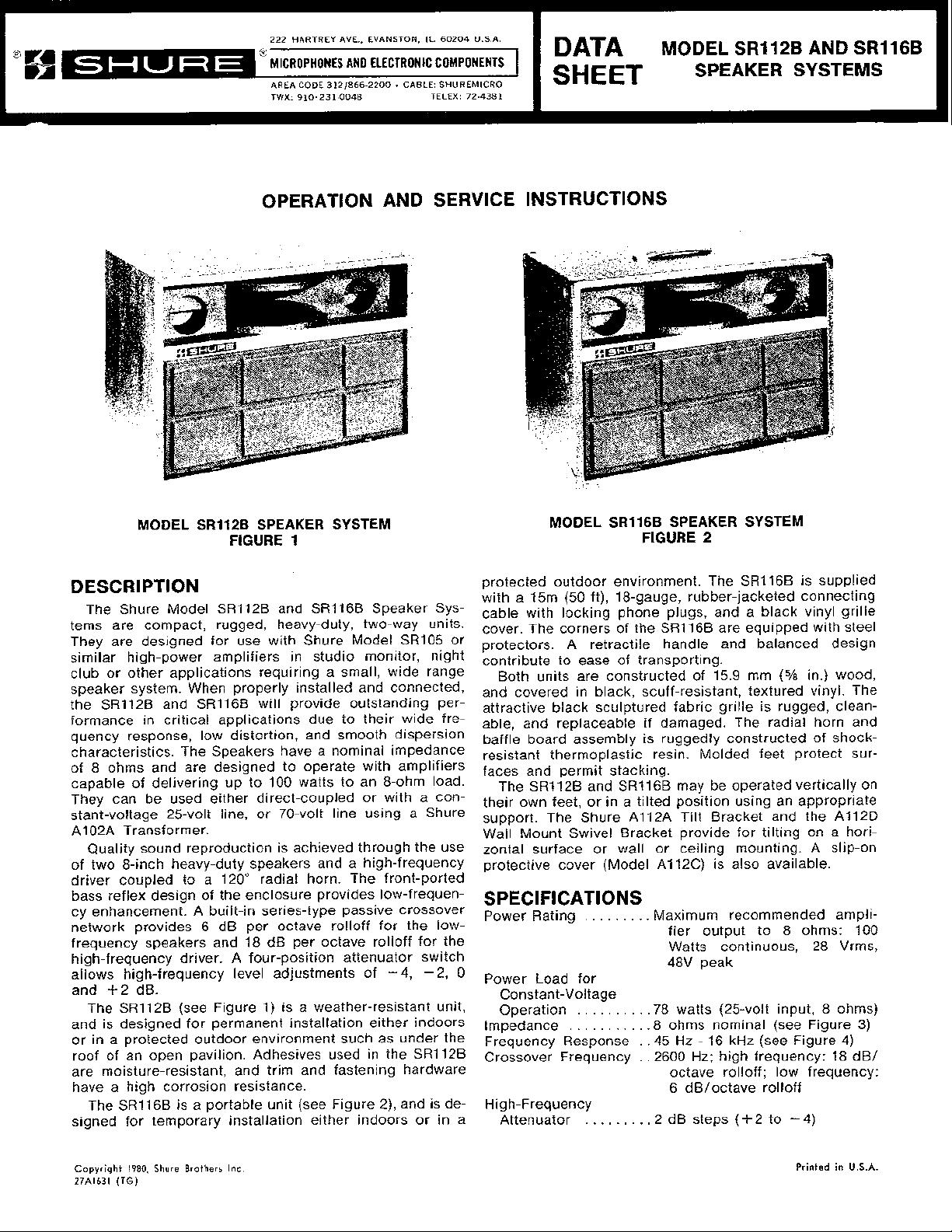
MODEL SR112B SPEAKER SYSTEM
FIGURE
1
DESCRIPTION
The Shure Model SR112B and SR116B Speaker Systems are compact, rugged, heavy-duty, two-way units.
They are designed for use with Shure Model
similar high-power amplifiers in studio monitor, night
club or other applications requiring a small, wide range
speaker system. When properly installed and connected,
SR112B and SR116B will provide outstanding per-
the
formance in critical applications due to their wide frequency response, low distortion, and smooth dispersion
characteristics. The Speakers have a nominal impedance
of 8 ohms and are designed to operate with amplifiers
capable of delivering up to 100 watts to an 8-ohm load.
They can be used either direct-coupled or with a constant-voltage 25-volt line, or 70-volt line using a Shure
A1 02A Transformer.
Quality sound reproduction is achieved through the use
of two 8-inch heavy-duty speakers and a high-frequency
driver coupled to a 120" radial horn. The front-ported
bass reflex design of the enclosure provides
cy enhancement. A built-in series-type passive crossover
network provides 6 dB per octave
frequency speakers and 18 dB per octave rolloff for the
high-frequency driver. A four-position attenuator switch
allows high-frequency level adjustments of -4, -2,
and
+2
dB.
The SR112B (see Figure 1) is a weather-resistant unit,
and is designed for permanent installation either indoors
or in a protected outdoor environment such as under the
roof of an open pavilion. Adhesives used in the
are moisture-resistant, and trim and fastening hardware
have a high corrosion resistance.
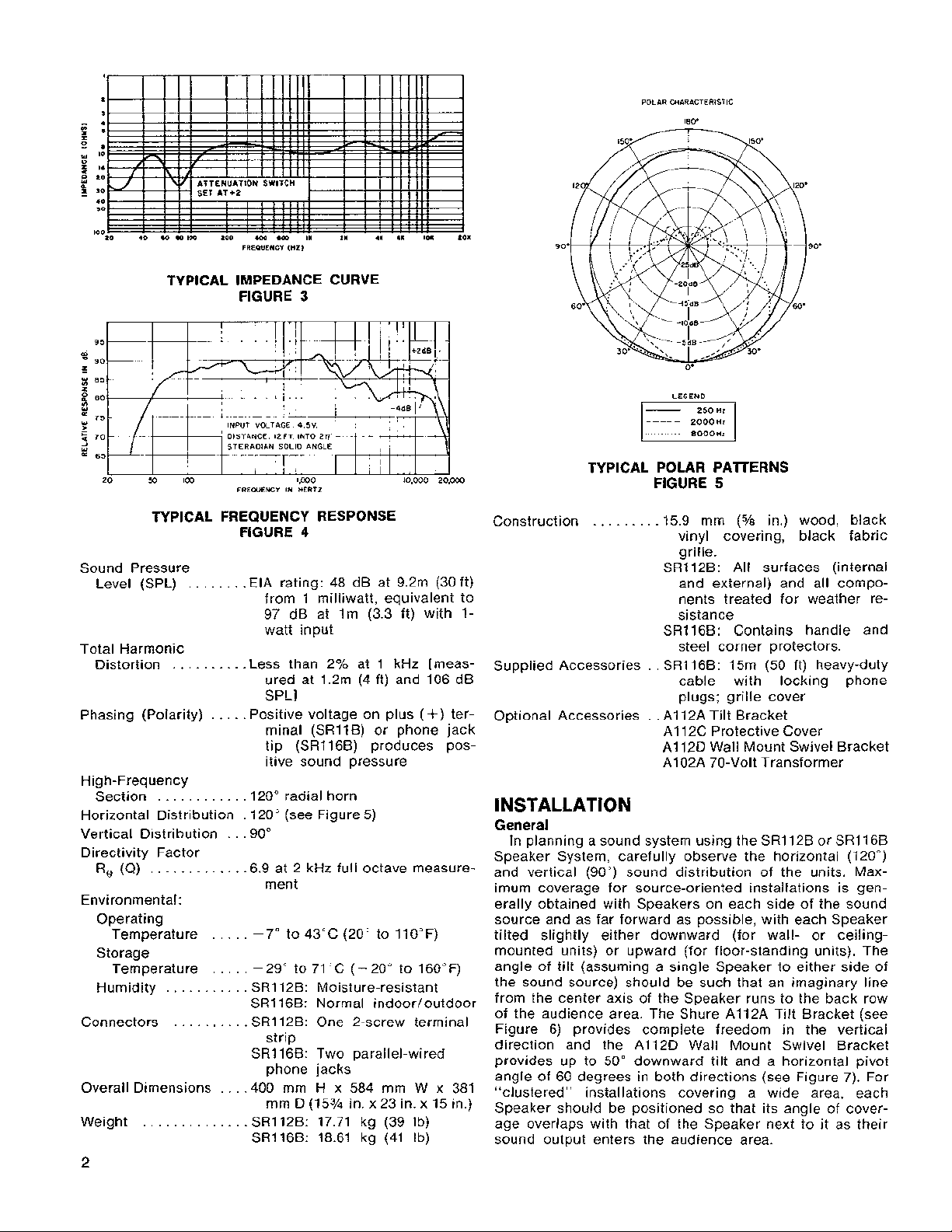
SR116B is a portable unit (see Figure 2), and is de-
The
signed for temporary installation either indoors or in a
rolloff for the low-
SR105 or
low-frequen-
SR112B
MODEL SR116B SPEAKER SYSTEM
FIGURE
protected outdoor environment. The SR116B is supplied
with a 15m (50 ft), 18-gauge, rubber-jacketed connecting
cable with locking phone plugs, and a black vinyl grille
cover. The corners of the
protectors. A retractile handle and balanced design
contribute to ease of transporting.
and covered in black, scuff-resistant, textured vinyl. The
attractive black sculptured fabric grille is rugged, cleanable, and replaceable if damaged. The radial horn and
baffle board assembly is ruggedly constructed of
resistant thermoplastic resin. Molded feet protect surfaces and permit stacking.
their own feet, or in a tilted position using an appropriate
support. The Shure
Wall Mount Swivel Bracket provide for tilting on a horizontal surface or wall or ceiling mounting. A slip-on
protective cover (Model
units are constructed of 15.9 mm
Both
SR112B and SR116B may be operated vertically on
The
A112A Tilt Bracket and the A112D
A112C) is also available.
2
SR116B are equipped with steel
(5h
in.) wood,
SPECIFICATIONS
.
. . .
.
.
.
. .
Power Rating
0
Power Load for
Constant-Voltage
Operation
Impedance
Frequency Response . .45
Crossover Frequency
High-Frequency
Attenuator
. .
.
.
. . .
.
. .
. .
. .
Maximum recommended ampli-
fier output to 8 ohms: 100
Watts continuous, 28 Vrms,
48V peak
.
. . .
.78 watts (25-volt input, 8 ohms)
.
. . .
.
.8 ohms nominal (see Figure
Hz
-
.
,2600 Hz; high frequency: 18 dB/
. .
. .
.2 dB steps (+2 to - 4)
16 kHz (see Figure 4)
octave
6
rolloff; low frequency:
dB/octave rolloff
shock-
3)
Copyright
27Al631
1980.
(TG)
Shure Brothers
inc.
Printed
in
U.S.A.
m
-
Z
-
z
g
=
>
5
.""
95
90
a5
80
75
70
65
20
POLAR CHARACTERISTIC
18V
I
I
1
11
400
1111
.00
In21
1 I 1
11
Zl
4
11
1111
S
101
101
ATTENUATION SWITCH
10
40 60
W
100
ZOO
FREQUENCY
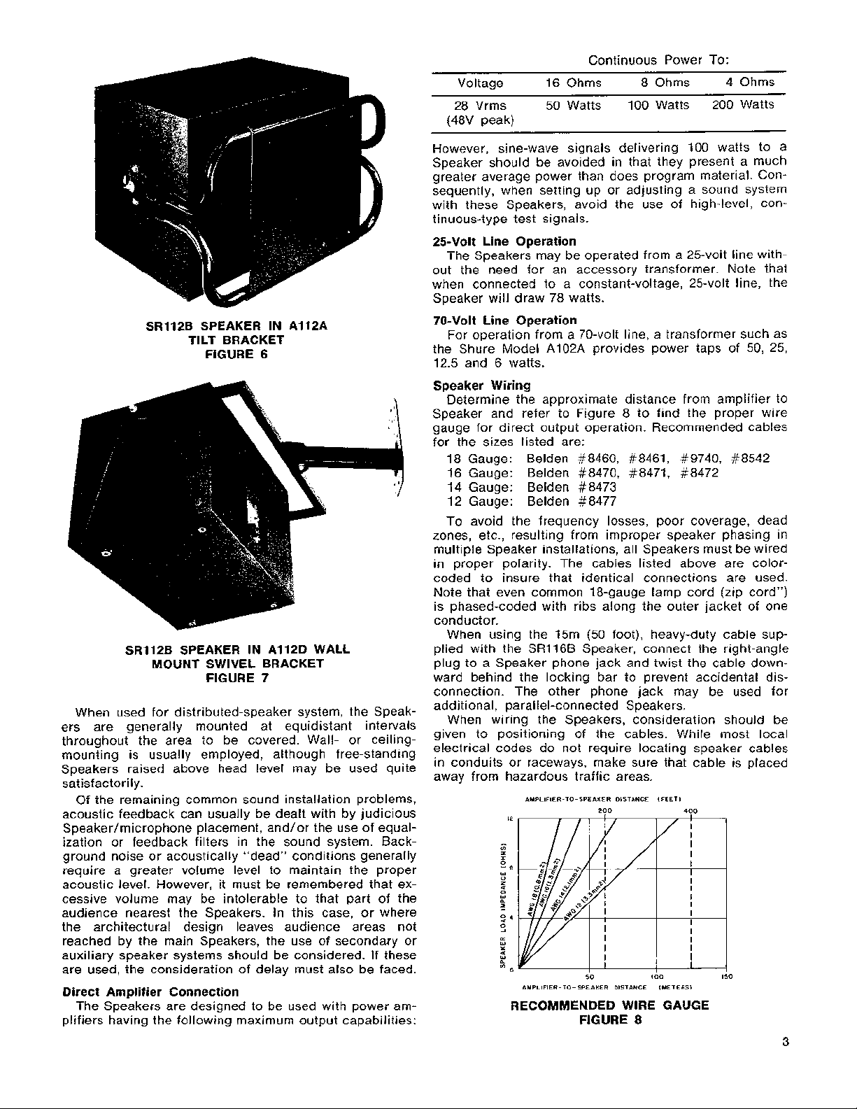
TYPICAL IMPEDANCE CURVE
FIGURE
M
100
FREWENCY IN HERTZ
3
lW0 10,000 20,000
LEGEND
-----
2000
HZ
TYPICAL POLAR PATERNS
FIGURE
5
TYPICAL FREQUENCY RESPONSE
FIGURE
4
Sound Pressure
Level (SPL) EIA rating: 48 dB at 9.2m (30 ft)
........
from 1
milliwatt, equivalent to
97 dB at lm (3.3 ft) with 1watt input
Total Harmonic
Distortion
..........
Less than 2% at 1 kHz [meas-
ured at 1.2m (4 ft) and 106 dB
SPLI
Phasing (Polarity)
Positive voltage on plus
.....
(+)
minal (SR11B) or phone jack
tip (SRll6B) produces pos-
itive sound pressure
High-Frequency
Section .120° radial horn
Horizontal Distribution
Vertical Distribution
...........
...
.
120" (see Figure 5)
90"
Directivity Factor
R,
(Q)
............
.6.9 at 2 kHz full octave measure-
ment
Environmental:
Operating
.....
-
Temperature
7" to 43°C (20" to 110°F)
Storage
Temperature
Humidity
.....
...........
-
29" to 71 "C (-20" to 160°F)
SR112B: Moisture-resistant
SR116B: Normal indoor/outdoor
Connectors
..........
SR112B: One 2-screw terminal
strip
SR116B: Two parallel-wired
phone jacks
Overall Dimensions
...
,400 mm H x 584 mm W x 381
mm D (15% in. x 23 in. x 15 in.)
Weight
..............
SR112B: 17.71 kg (39 Ib)
SR116B: 18.61 kg (41 Ib)
Construction 15.9 mm
.........
(%
in.) wood, black
vinyl covering, black fabric
grille.
SR112B: All surfaces (internal
and external) and all components treated for weather resistance
SR116B: Contains handle and
steel corner protectors.
.
.
Supplied Accessories
SR116B: 15m (50 ft) heavy-duty
cable with locking phone
plugs; grille cover
ter-
Optional Accessories
.
.
A1 12A Tilt Bracket
A1 12C Protective Cover
A1 12D Wall Mount Swivel Bracket
A102A 70-Volt Transformer
INSTALLATION
General
In planning a sound system using the SR112B or SR116B
Speaker System, carefully observe the horizontal (120")
and vertical (90") sound distribution of the units. Maximum coverage for source-oriented installations is generally obtained with Speakers on each side of the sound
source and as far forward as possible, with each Speaker
tilted slightly either downward (for wall- or
mounted units) or upward (for floor-standing units). The
angle of tilt (assuming a single Speaker to either side of
the sound source) should be such that an imaginary line
from the center axis of the Speaker runs to the back row
of the audience area. The Shure
Figure 6) provides complete freedom in the vertical
direction and the
provides up to
A112D Wall Mount Swivel Bracket
50" downward tilt and a horizontal pivot
angle of 60 degrees in both directions (see Figure 7). For
"clustered" installations covering a wide area, each
Speaker should be positioned so that its angle of cover-
age overlaps with that of the Speaker next to it as their
sound output enters the audience area.
A112A Tilt Bracket (see
ceiling-
SRl12B SPEAKER IN A112A
BRACKET
TILT
FIGURE
6
SRl12B SPEAKER IN A112D WALL
MOUNT SWIVEL BRACKET
FIGURE 7
When used for distributed-speaker system, the Speakers are generally mounted at equidistant intervals
throughout the area to be covered. Wall- or ceilingmounting is usually employed, although free-standing
Speakers raised above head level may be used quite
satisfactorily.
Of the remaining common sound installation problems,
acoustic feedback can usually be dealt with by judicious
Speakerlmicrophone placement, and/or the use of equalization or feedback filters in the sound system. Background noise or acoustically "dead" conditions generally
require a greater volume level to maintain the proper
acoustic level. However, it must be remembered that ex-
cessive volume may be intolerable to that part of the
audience nearest the Speakers. In this case, or where
the architectural design leaves audience areas not
reached by the main Speakers, the use of secondary or
auxiliary speaker systems should be considered. If these
are used, the consideration of delay must also be faced.
Direct Amplifier Connection
The Speakers are designed to be used with power am-
plifiers having the following maximum output capabilities:
Continuous Power To:
Voltage 16 Ohms 8 Ohms 4 Ohms
28
Vrms 50 Watts 100 Watts 200 Watts
(48V peak)
However, sine-wave signals delivering 100 watts to a
Speaker should be avoided in that they present a much
greater average power than does program material. Con-
sequently, when setting up or adjusting a sound system
with these Speakers, avoid the use of high-level, continuous-type test signals.
25-Volt Line Operation
The Speakers may be operated from a 25-volt line without the need for an accessory transformer. Note that
when connected to a constant-voltage, 25-volt line, the
Speaker will draw 78 watts.
70-Volt Line Operation
For operation from a 70-volt line, a transformer such as
the Shure Model A102A provides power taps of 50, 25,
12.5 and 6 watts.
Speaker Wiring
Determine the approximate distance from amplifier to
Speaker and
refer to Figure 8 to find the proper wire
gauge for direct output operation. Recommended cables
for the sizes listed are:
18 Gauge:
Belden #8460, #8461, #9740, #8542
16 Gauge: Belden #8470, #8471, #8472
14 Gauge: Belden #8473
12 Gauge: Belden #8477
To avoid the frequency losses, poor coverage, dead
zones, etc., resulting from improper speaker phasing in
multiple Speaker installations, all Speakers must be wired
in proper polarity. The cables listed above are
colorcoded to insure that identical connections are used.
Note that even common 18-gauge lamp cord (zip cord")
is phased-coded with ribs along the outer jacket of one
conductor.
When using the 15m (50 foot), heavy-duty cable sup-
plied with the
SRl16B Speaker, connect the right-angle
plug to a Speaker phone jack and twist the cable down-
ward behind the locking bar to prevent accidental dis-
connection. The other phone jack may be used for
additional, parallel-connected Speakers.
When wiring the Speakers, consideration should be
given to positioning of the cables. While most local
electrical codes do not require locating speaker cables
in conduits or raceways, make sure that cable is placed
away from hazardous traffic areas.
AMPLIFIER-TO-SPEAKER DISTANCE (FEET)
AMPLIFIER-TO-SPEAKER DISTANCE IMETERSl
200 400
50 100 150
RECOMMENDED WIRE GAUGE
FIGURE
8

Installation
The
SRll2B and SR116B may be operated free-standing,
either on their own feet or on a Shure
or suspended on a wall or ceiling using an
A112D Wall Mount Swivel Bracket. In positioning the
Speakers for optimum sound coverage, care must be
taken to locate the Speakers away from areas where
they may interfere with the movement of performers,
audience, curtains or stage sets.
If the Speaker is to be used at low power on a constant-voltage, 70-volt system, a Shure Model
70-Volt Transformer must be connected between the am-
plifier and Speaker. The transformer should be located as
close to the Speaker as possible; therefore the optimum
mounting location just above the connector panel should
be used. Mounting of the transformer adds approximately
82 mm
Checking Sound Coverage
have been installed and connected, apply a fairly constant level signal to the system (preferably program
material) and walk around the audience area. Listen for
a smooth, even output from the Speakers, with minimal
differences in volume and tone, and no distortion or
"dead spots." A dead spot-for audio purposes, an
audience area where no sound is heard, or where the
sound level is appreciably lower-may mean that the
Speakers are not covering that area, or that the speaker
wires are connected out-of-phase. Proper phasing may be
readily determined by checking the connections on each
Speaker, but inadequate coverage generally requires repositioning the Speakers. The dead area should be carefully examined to determine that the problem can be
corrected without resorting to auxiliary speakers.
(3Y4 in.) to the total depth of the Speaker.
When the Speakers, amplifier and other equipment
A112A Tilt Bracket,
A112A or an
A102A
SERVICE INSTRUCTIONS
Speaker Servicing
1. Disconnect speaker cables from phone jacks or
terminal strip.
2. Using an ohmmeter, measure the resistance be-
(+)
tween the plus
or tip and sleeve of phone jack. The dc resistance
should be
3. To gain access to the individual speakers, remove
the grille by pulling the two cloth tabs at the bottom of the grille. Remove the screws securing the
horn/baffle board assembly. Remove the horn/
baffle board assembly, taking care not to stress
the wiring.
4.
Using an ohmmeter, measure the resistance of each
speaker voice coil. A clicking sound will be made
by a "good" speaker when an ohmmeter is connected or disconnected. Note that the resistance of
each 8-inch speaker cannot be measured without
disconnecting one lead connecting the two speakers. Each 8-inch speaker should measure between
11 and 13 ohms. With its leads disconnected, the
high-frequency driver should measure between 6.7
and 7.7 ohms.
5.
If the above tests do not locate the problem unit,
apply a small ac voltage from an oscillator and amplifier to each speaker individually (approximately
4V,
mately 2V, 3 kHz to
speakers).
5.5
50 Hz to 5 kHz for 8-inch speakers; approxi-
and minus
to 7 ohms.
15
(-)
terminal screws
kHz for high-frequency
WARNING
Sound pressure levels generated by this test may
be damaging to your hearing. Aim speakers away
from listeners and toward sound-absorbent material
(curtains, blanket, etc.). Carefully adjust test signal
amplitude to avoid unnecessarily high sound pressure levels for prolonged periods.
As the test signal frequency is varied, any erratic
buzzes or rattles indicate possible failure.
6. Reconnect, replace and tighten the 8-inch speakers. Reconnect the high-frequency driver and replace the
hardware to avoid rattles.
High-Frequency Driver Replacement
To replace the high-frequency driver, follow these steps:
1. Remove grille assembly and
described in Speaker Servicing.
2. Remove leads from driver terminals. Note color
coding of speaker wires.
3. For earlier production units, remove three 6-32 x
1
Ye
horn/baffle board. For later production units, re-
move two 10-16 x 1 in. screws holding driver
mounting plate to
mounting plate and driver from
4.
Replace driver diaphragm and voice coil assembly
as described in High-Frequency Diaphragm and
Coil Replacement instruction sheet.
5.
For earlier production units, carefully place repaired
or new high-frequency driver in position over
baffle/board,
over holes in
terminals are positioned downward (toward
frequency speakers). Replace three 6-32 x 1% in.
screws, and tighten high-frequency driver assembly.
6. For later production units, carefully place repaired
or new high-frequency driver in position over horn/
baffle board with driver terminals downward (toward
low-frequency speakers). Position driver mounting
plate over driver, lining up holes in mounting plate
over threaded holes in
two 10-16
7. Replace removed driver leads. Note polarity marking on driver.
~ssemble horn/baffle board and grille to enclo-
8.
?
Nameplate
Should it become necessary to replace or re-fasten the
front-panel nameplate, be sure to use a heavy-duty
weather-resistant adhesive.
equivalent cement is recommended.
ACCESSORIES
The following optional accessories are available for use
SR112B and SRl16B Speakers:
with
A112A Tilt Bracket permits 360" rotation of the Speaker
about a horizontal axis. Heavy-duty tubular steel with a
flat steel baseplate that provides stable floor or shelf for
horn/baffle board and grille. Tighten all
horn/baffle board as
in. screws securing high-frequency driver to
horn/baffle board. Remove driver
horn/baffle board.
horn/
taking care to line up holes in driver
horn/baffle board. Be sure that driver
low-
horn/baffle board. Replace
x
1 in. screws, and tighten securely.
and fasten securely to avoid rattles.
Goodyear PLIOBOND or

portable positioning in stage monitor use, or wall or ceiling mounting for permanent installations.
A112D Wall Mount Swivel Bracket provides up to 50"
of downward tilt, and up to f 60" of horizontal rotation
when mounted on a vertical surface.
A112C Slip-On Cover is a heavy vinyl cover that pro-
vides protection for the Speaker. Has a handle cut-out
for the
50, 25, 12, and 6 watts for 70-volt distributed systems, and
impedance taps of 8 to 16 ohms. Mounts easily to the
back of a speaker or convenient surface.
GUARANTEE
free from electrical and mechanical defects for a period
of one year from date of purchase. Please retain proof of
purchase date. This guarantee includes all parts and
labor. This guarantee is in lieu of any and all other guar-
antees or warranties, express or implied, and there shall
be no recovery for any consequential or incidental
damages.
SHIPPING INSTRUCTIONS
If outside the United States, return the unit to your
dealer or Authorized Shure Service Center for repair.
The unit will be returned to you prepaid.
SRl16B Speaker.
A102A 70-Volt Transformer provides wattage taps of
This Shure product is guaranteed in normal use to be
Carefully repack the unit and return it prepaid to:
Shure Brothers Incorporated
Attention: Service Department
1501 West Shure Drive
Arlington Heights, Illinois 60004
ARCHITECTS' AND ENGINEERS'
SPECIFICATIONS
SR112B Speaker
The Speaker shall be a speaker designed for indoor or
outdoor use in sound reinforcement or studio monitor ap-
plications. The Speaker shall utilize two
speakers and one high-frequency driver. The Speaker
shall have an EIA sensitivity rating of
(30 feet) from 1 milliwatt (equivalent to 97 dB at lm-
3.3 feet-with a 1-watt input).
The sound pressure distribution shall be nominally uni-
form over a 120" angle in the horizontal plane and a
angle in the vertical plane.
The usable frequency response of the Speaker shall be
uniform and peak-free from 45 Hz to 16,000 Hz.
Nominal impedance of the Speaker shall be 8 ohms
and it shall be designed to operate with amplifiers delivering up to 100 watts to an
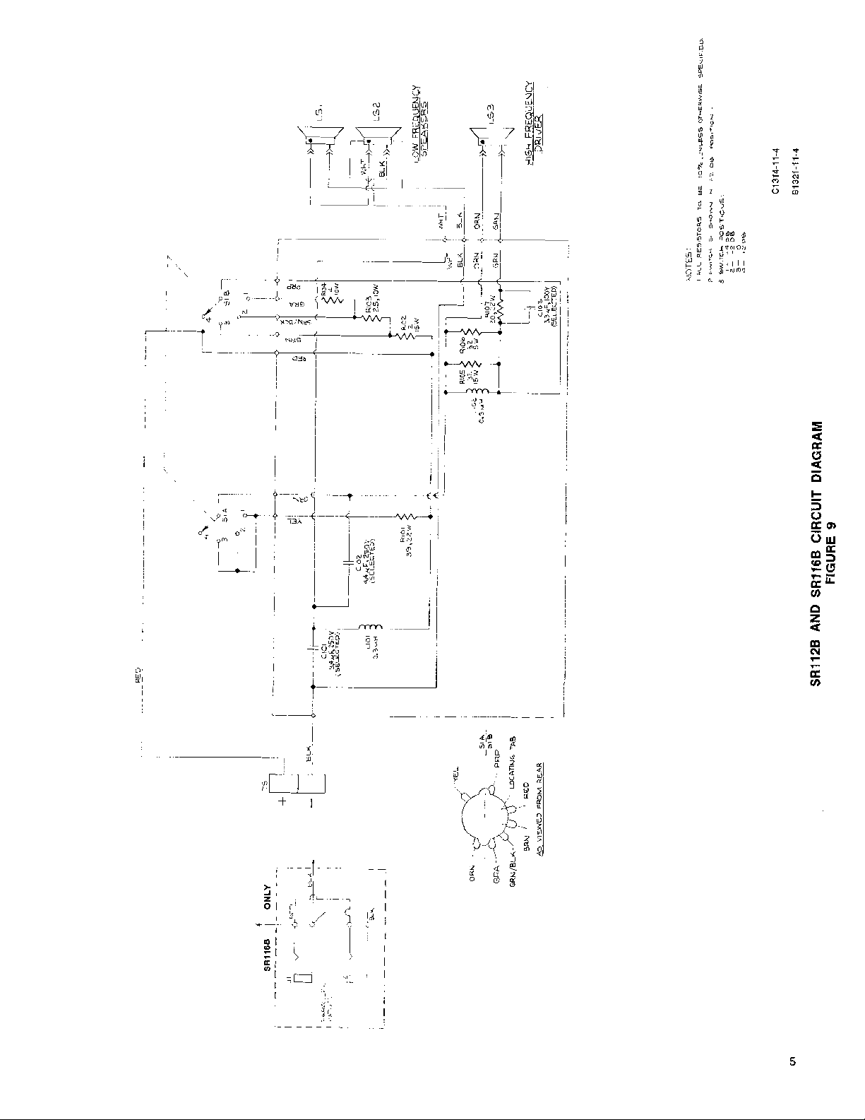
The speakers shall be wired with a 2600 Hz crossover
network in a series-parallel configuration and connected
to a two-terminal barrier terminal strip.
&ohm load.
&inch cone-type
48
dB at 9.2m
90"
(Ti
(Ye
in.) wood
(15% in.
Ib.).
in.) wood
Ib.).
The speaker enclosure shall be 15.9 mm
construction covered with black, scuff-resistant vinyl and
a removable, sculpture fabric grille. Molded feet protect surfaces and permit stacking. All surfaces (internal and external) and all components shall be treated for
weather resistance. The Speaker shall measure 400 mm in
height, 584 mm in width, and 381
x 23 in. x 15 in.). The weight shall be 16.75 kg (37
The operating temperature range of the Speaker shall be
-7°C to 43°C (20°F to 110°F). The storage temperature
range shall be -29°C to 71°C (-20°F to 160°F). The
Speaker shall meet all specifications when operating
within the operating temperature limits.
Any Speaker not meeting all the above specifications,
or having a sealed cabinet which prevents internal inspection and servicing, shall be deemed unacceptable
under this specification. The Speaker shall be a Shure
Model
SR116B
sound reinforcement or studio monitor applications. The
Speaker shall utilize two 8-inch cone-type speakers and
one high-frequency driver. The Speaker shall have an
EIA sensitivity rating of 48 dB at 9.2m (30 feet) from 1
milliwatt (equivalent to 97 dB at lm-3.3 feet-with
1-watt input).
uniform over a 120" angle in the horizontal plane and 90"
angle in the vertical plane.
uniform and peak-free from 45 Hz to 16,000 Hz.
it shall be designed to operate with amplifiers delivering
up to 100 watts to an 8-ohm load.
network in a series-parallel configuration and connected
to two phone jacks.
construction covered with black, scuff-resistant vinyl
and a removable, sculptured fabric grille. Molded feet
protect surfaces and permit stacking. The enclosure
shall have a retractile handle for portability. A plug-in 15m
(50 ft) speaker cable shall be supplied. The Speaker shall
measure 400 mm in height, 584 mm in width, and 381 mm
in depth (15% in. x 23 in. x 15 in.). The weight, less
supplied cable and grille cover, shall be 17.21 kg (38
-7°C to 43°C (20°F to 110°F). The storage temperature
range shall be -29°C to 71°C (-20°F to 160°F). The
Speaker shall meet all specifications when operated within the operating temperature limits.
tions, or having a sealed cabinet which prevents internal
inspection and servicing, shall be deemed unacceptable
under this specification. The Speaker shall be a Shure
Model
SR112B.
Speaker
The Speaker shall be a portable speaker designed for
The sound pressure distribution shall be nominally
The usable frequency response of the Speaker shall be
Nominal impedance of the Speaker shall be 8 ohms and
The speakers shall be wired with a 2600 Hz crossover
The speaker enclosure shall be 15.9 mm
The operating temperature range of the Speaker shall be
Any Speaker not meeting all of the above specifica-
SR116B.
mm in depth
a

REPLACEMENT PARTS LIST
(see
Figure
10)
Reference
Designation
A1
A2
C101
C102
C103
J1, J2
Ll 01
L102
LSI, LS2
LS3
MPI
MPI
M P2
M P2
M P3
M P4
P5
M
MP6
M P6
MP7
M P8
P9
M
MPlO
MP11
MP12
MP13
MP14
Replacement
Kit No.*
-
RKC153**
RKC156*
*
-
-
-
-
-
-
RKC162
-
-
-
-
-
RKC39
-
7
-
RKCI 59
-
-
-
-
-
-
-
RKCl61
-
Qty.
-
1
1
-
-
-
-
-
-
-
-
-
-
-
-
4
-
-
-
1
-
-
-
-
-
-
-
-
1
-
Part No.
90A2752
80231 6
80Y316
50F71
50E71
50G71
90BA2600
95A823
95A647
80A346
80A316*
80B316**
80C316*
60A73
60B73
65A1001
66A158
65A1338A
39A438
90B2756
53A1559
53A1576
90BC2600
53A1656B
30A1002B
30H903C
30A882B
30A1087A
95A888
53A1775
A
Replacement Kit Consists Of:
Description
Crossover Network Assembly (with Switch)
High-Frequency Diaphragm and Coil
Capacitor, Mylar, 9.4
Capacitor, Mylar, 4.4 pF, lo%, 250 WVdc *
Capacitor, Mylar, 3.3 pF, lo%, 100 WVdc *
Connector, Phone Jack, 2-Conductor, Open
Circuit (SRI
Inductor, 0.3
Inductor, 0.5 mH
8-inch Loudspeaker
*
*
High-Frequency Driver (see A2 for
replacement diaphragm and coil assembly)
SRI12B Speaker Enclosure Assembly (including Fiber Glass; without Speakers, Crossover
Network,
sembly, Nameplate)
SR116B Speaker Enclosure Assembly (includ-
ing Fiber Glass, Handle, Corner Protectors;
without Speakers, Crossover Network,
Baffle Board, Feet, Grille Assembly, Name-
plate)
Foot, Plastic
Foot, Rubber
HornIBaffle Board
Nameplate
Grille Assembly
Connector Plate (without Connectors)
Connector Plate (without Connectors) (SR116B)
Retractile Handle Assembly (SR116B only)
Corner Protector (SRI
Carriage Bolt, Aluminum, 2" (Crossover
Network)
Phillips Round Head Machine Screw,
3hn
(Feet)
Phillips Flat Head Wood Screw, #6,
1%'' (HornIBaffle Board)
Oval Head Steel Drive Screw, #6,
%
"
(Corner Protectors) (SR116B only)
Grille Cover
Driver Mounting Plate
I6B only)
mH
HornIBaffle Board, Feet, Grille As-
(SR116B only)
pF, lo%, 250 WVdc * * *
16B only)
* *
*
*
Horn/
(SRI 128)
#lo-32,
*
Parts listed as RKC Kits should be ordered by that kit number. Any orders received for piece parts where RKC Kit number
is shown will be shipped in RKC quantities.
**
Replacement diaphragm and coil assemblies
RKC156. Inspect driver for part number.
* * *
Selected for low dissipation factor.
not
interchangeable: 80A316 driver uses RKC153; 80B316 and 806316 use
7

REPLACEMENT PARTS LIST
(see
Figure
10)
Reference
Designation
MP15
R101
R102
R103
R104
R105, R106
R107
S 1
TSl
W1
*
Parts listed
shown will be shipped in RKC quantities.
as
RKC Kits should be ordered by that kit number. Any orders received for piece parts where RKC Kit number is
Replacement
Kit No.*
-
-
-
-
-
-
-
-
-
RKC4
Qty.
-
-
-
-
-
-
-
-
-
1
Part No.
30F1154A
45EC390G
45HC208E
45HC258D
45HC408D
45HC320F
45EC200G
55A125
56A211
90C1373
Replacement Kit Consists Of:
Description
Phillips Pan Head Thread-Forming Screw,
#lo-16, 1" (Driver)
Resistor, Wirewound, 39 ohms,
Resistor, Wirewound, 2 ohms,
Resistor, Wirewound, 2.5 ohms,
Resistor, Wirewound, 4 ohms,
Resistor, Wirewound, 32 ohms,
Resistor, Wirewound, 20 ohms,
Switch, Rotary, 2-Pole, 4-Position
Terminal Strip, 2-Screw
15m (50 ft) Cable Assembly with Male Phone
(SRI16B only)
Plugs
(SRl12B only)
22W, 10%
15W, 10%
10W, 10%
low, 10%
15W, 10%
22W, 10%
NOTE : SR112B SHOWN : SRIIGB PARTS DESCRIBED
IN REPLACEMENT PARTS LIST
EXPLODED VIEW
FIGURE
10
 Loading...