

Shure SR110-2E Datasheet
I
222
HARTREY
AVE..
EVANSTON. IL.
60204 U.S.A.
1
MODEL SR110 A)
.--
-
8
qD
MICROPHONES
AND
ELECTRONIC
COMPONENTS
I
1
UW
A
SRI 10-2E
PROFESSIONAL
AKtA
I;uUt
31ZIXbb.ZZUU . LAMLt:
bHuKtMILKU
I
SHEET
MONITOR MIXERS
I
I
TWX:
910-231-0048 TELEX: 72-4381
I
OPERATION AND
DESCRIPTION
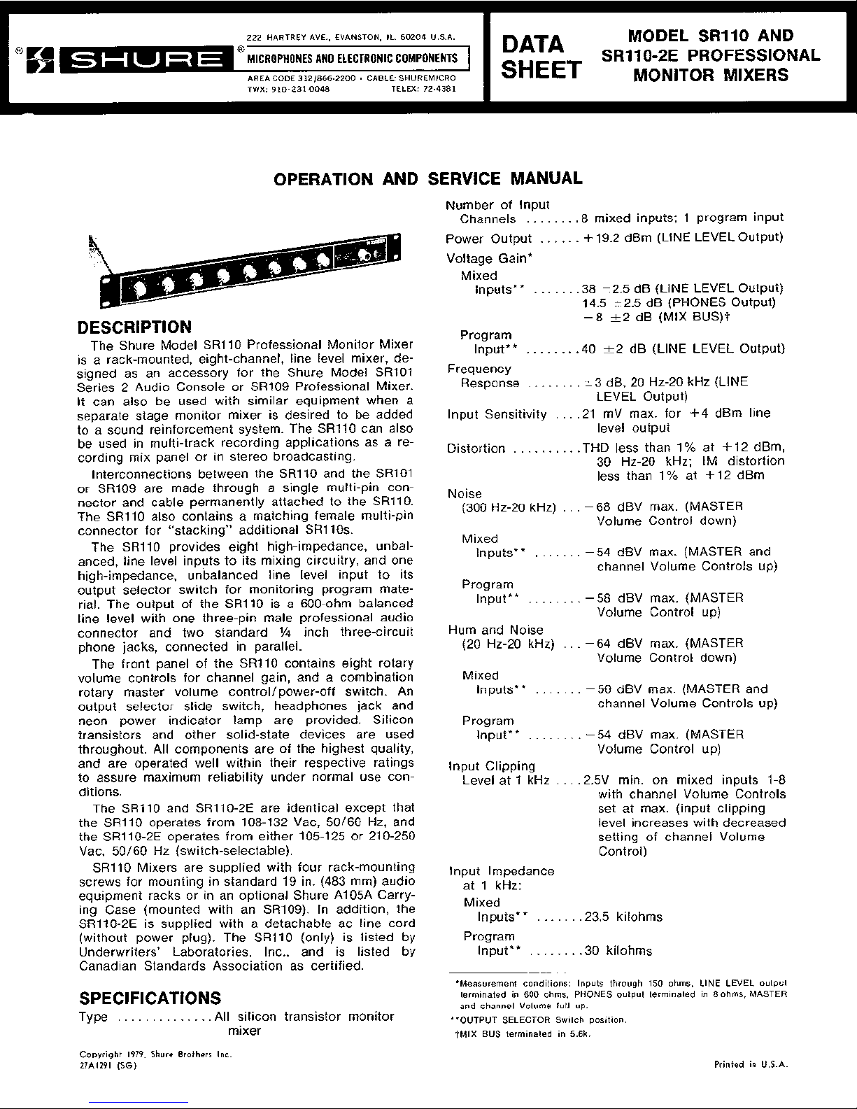
The Shure Model SR110 Professional Monitor Mixer
is a rack-mounted, eight-channel, line level mixer, de-
signed as an accessory for the Shure Model
SRlO1
Series 2 Audio Console or SR109 Professional Mixer.
It can also be used with similar equipment when a
separate stage monitor mixer is desired to be added
to a sound reinforcement system. The
SR110 can also
be used in multi-track recording applications as a recording mix panel or in stereo broadcasting.
Interconnections between the
SR110 and the SRlO1
or SR109 are made through a single multi-pin connector and cable permanently attached to the SRllO.
The
SR110 also contains a matching female multi-pin
connector for "stacking" additional
SRllOs.
The SR110 provides eight high-impedance, unbalanced, line level inputs to its mixing circuitry, and one
high-impedance, unbalanced line level input to its
output selector switch for monitoring program material. The output of the
SR110 is a 600-ohm balanced
line level with one three-pin male professional audio
connector and two standard
'/4
inch three-circuit
phone jacks, connected in parallel.
The front panel of the SRllO contains eight rotary
volume controls for channel gain, and a combination
rotary master volume controllpower-off switch. An
output selector slide switch, headphones jack and
neon power indicator lamp are provided. Silicon
transistors and other solid-state devices are used
throughout. All components are of the highest quality,
and are operated well within their respective ratings
to assure maximum reliability under normal use con-
ditions.
The
SR110 and SR110-2E are identical except that
the SRllO operates from 108-132 Vac, 50160 Hz, and
the
SRllO-2E operates from either 105-125 or 210-250
Vac, 50160 Hz (switch-selectable).
SR110 Mixers are supplied with four rack-mounting
screws for mounting in standard 19 in. (483 mm) audio
equipment racks or in an optional Shure
A105A Carry-
ing Case (mounted with an
SR109). In addition, the
SR110-2E is supplied with a detachable ac line cord
(without power plug). The
SRl10 (only) is listed by
Underwriters' Laboratories, Inc., and is listed by
Canadian Standards Association as certified.
SPECIFICATIONS
Type
.
. . . . . . . . .
. .
.
.All silicon transistor monitor
mixer
SERVICE MANUAL
Number of lnput
Channels
. . . . . . .
.8 mixed inputs; 1 program input
Power Output
. . . . .
.
+19.2 dBm (LINE LEVEL Output)
Voltage Gain*
Mixed
Inputs**
. . .
. . .
.38 i2.5 dB (LINE LEVEL Output)
14.5
t2.5 dB (PHONES Output)
-8
+-2
dB (MIX BUS)t
Program
Input**
. . . . . .
.
.40 +-2 dB (LINE LEVEL Output)
Frequency
Response
. . .
lnput Sensitivity
.
. .
Distortion
. .
. . . . .
.
.
Noise
(300 HZ-20
kHz)
Mixed
Inputs**
.
. . . . .
.
i3 dB, 20 Hz-20 kHz (LINE
LEVEL Output)
.21
mV max. for +4 dBm line
level output
.THD less than 1 % at + 12 dBm,
30 Hz-20 kHz; IM distortion
less than 1 % at +12 dBm
.
-
68 dBV max. (MASTER
Volume Control down)
.
-54 dBV max. (MASTER and
channel Volume Controls up)
Program
Input**
. . .
. . . . .
-58 dBV max. (MASTER
Volume Control up)
Hum and Noise
(20 Hz-20 kHz)
. .
.
-
64 dBV max. (MASTER
Volume Control down)
Mixed
Inputs**
. . . . . . .
-50 dBV max. (MASTER and
channel Volume Controls up)
Program
Input**
.
. . .
. . . .
-54 dBV max.
(MASTER
Volume Control up)
lnput Clipping
Level at
1 kHz
. . .
.2.5V min. on mixed inputs 1-8
with channel Volume Controls
set at max. (input clipping
level increases with decreased
setting of channel Volume
Control)
lnput Impedance
at 1 kHz:
Mixed
Inputs**
. . . . . .
.23.5
kilohms
Program
Input**
. . . .
. . .
.30
kilohms
*Measurement conditions: Inputs through
150
ohms, LINE LEVEL output
terminated in
600
ohms,
PHONES
output terminated in 8 ohms,
MASTER
and channel Volume full up.
**OUTPUT SELECTOR
Switch position.
+MIX
BUS
terminated
in
5.6k.
Copyright 1979, Shure Brothers Inc
27A1291
(56)
Printed in
U.S.A.

FIGURE A. SR110 FRONT PANEL
4
Output Impedances: 3. MASTER Volume Rotary Control/POWER OFF
Line Level
.
. . . .
..Balanced 120 ohms actual (for Switch-Adjusts level of total monitor output and
use with 600-ohm lines)
applies ac power to power supply.
Headphone
. . . .
.
.12 ohms actual (for use with 4-
4.
PHONES Output Jack-Provides for connection of
to 16-ohm headphones)
stereo or monophonic headphones for monitoring.
Mix Bus
. . . . . .
.
.
.5.6 kilohms 5. OUTPUT SELECTOR Slide Switch-Selects be-
Phasing
. . .
.
. . . . . . .Pins 1 through 8 of ACCESSORY
tween signal mixed in SRllO (MIXED INPUTS) or
connector are out of phase
mixed in
SRlO1 or SR109 (PROGRAM INPUT).
with,
and
pin 9
is
in phase
6. MONITOR OUTPUTS/LINE LEVEL Three-Circuit
with, pin 3 of
LlNE LEVEL out-
Phone Jacks (Two)-Provide balanced Monitor
put
&pin connector, tips of
Mixer output connection to power amplifier or
LINE LEVEL and PHONES recording equipment.
jacks,
and
tip
of
MIX
BUS
7. MONITOR OUTPUTS/LINE LEVEL 3-Pin Male
phono pin jack
Connector-Provides balanced Monitor Mixer output connection to power amplifier or recording
Controls
. . . .
. . . . . . .Channel Volume: rotary, linear
taper; MASTER Volume:
equipment.
rotary, audio taper
8. ACCESSORY INPUT AND OUTPUT Cable
&
Multi-
Pin Male Connector-Provides for input connec-
Operating Voltage
. . .
SR110: 108-132 Vac, 50/60 Hz.
tions from Shure
SR101 or SR109 or similar equip-
SR110-2E:
105-1 25 or 21 0-250
ment.
Vac, 50/60 Hz.
9. ACCESSORY INPUT AND OUTPUT Multi-Pin
Fe-
Power
male Connector-Provides for connection of
addi-
Consumption
. . . .
.3 watts max. (Mixer only)
tional parallel-wired (tandem)
SRll 0s.
500
watts
max. (non-switched
10. MIX BUS Phono Jack-Provides common mix bus
ac receptacle)
(SR110 only)
when two
SRlOls or SRlO9s and two SRllOs are
Temperature:
to be operated in a common mix mode.
Operating
. . .
. .
. . . -7" to 54°C (+20° to 130°F) 11. Ac Grounded Line Cord-Connects ac power
Storage
. . . . . .
. . . -29" to 71°C (-20" to 160°F)
source to
SR110 power supply (SRllO only).
Dimensions
. . . . . . . .44.4 mm height X 483 mm 12. Non-Switched Ac Grounded Receptacle-Provides
width X 232 mm depth (1
3/4
in.
up to 500 watts of non-switched ac power to
ac-
X 19 in. X 9% in.)
cessory equipment
(SR110 only).
Weight
. .
. . .
. . . . .
. .3.9
kg (8 Ib, 8 oz)
13. AC (MAINS) POWER 3-Pin Connector-Connects
Finish
. . . . .
.
. .
. . . . .
Matte
black
unit to ac (mains) power source via supplied line
Installation
.
. . . .
. . . .Equipped for standard 19 in.
cord
(SR110-2E only).
(483 mm) audio rack mount-
14. VOLTAGE SELECTOR Slide Switch-Selects 105-
ing;
may be operated in
125V or 210-250V input power
(SR110-2E only).
optional-~105~' Carrying Case
(with
SR109)
General Operating Instructions
Certifications . . . . . . .Listed by Underwriters' Labora-
tories,
Inc.; listed by Canadian
Standards Association as
certified (SR110 only)
OPERATING
INSTRUCTIONS
Functional Description
(Refer to Figures A and B)
1. Individual Channel Volume Rotary Controls (Eight) 1. Using hardware provided, install
SR110 securely
-Control volume of each channel separately.
in standard 19 in. (483
mm) rack or optional A105A
2.
Power-On Indicator Lamp-Indicates ac power is Carrying Case (with SR109) prior to making
being applied to unit. electrical connections.
WARNING
To reduce the risk of fire or electric shock,
do not expose this appliance to rain or extreme moisture.
-
AC
IMAINS!
POWER
*'c,,X?,I
-0.'
.*O
OL'?.,
?..Ll.i..
I,&
.dl
1,1*
.:,
,,
2
>>.>
IL'
IT
w
"1
$",*I
/
13
\
SR110-2E
ONLY
14
FIGURE
B.
SR110 REAR PANEL
2.
Connect SR110 MONITOR OUTPUTS/LINE LEVEL
3-pin connector and/or phone jacks (7,
6)
to
power amplifier and/or recording equipment.
3. Connect
SR110 ACCESSORY INPUT AND OUT-
PUT Multi-Pin Male Connector
(8)
to SRlOl or
SR109.
4. If additional SRllO is to be used (tandem operation), connect ACCESSORY INPUT AND OUTPUT
Multi-Pin Male Connector (8) of second
SR110 to
ACCESSORY INPUT AND OUTPUT Female Connector (9) of first
SR110.
5. If common mix between two SRlOls or SRlO9s
and two SRllOs is desired, interconnect MIX BUS
Phono Jacks (10) of each SR110 and interconnect
the link output jacks of the SRlOls or
SRlO9s.
6. (SRl10-2E only) Move VOLTAGE SELECTOR
Switch (14) to 115V or 220V position as required.
7.
Connect ac line cord to grounded 108- to 132-volt
(SRl1 O), or 105-1 25V or 21 0-250V (SR110-2E),
50/60
Hz
ac source.
8. Turn on front-panel POWER OFF Switch on
MASTER Volume Control (3). Red indicator lamp
(2) will light, indicating power is being applied.
9. Adjust
SRlO1 or SR109 and associated power
amplifier for desired operating levels.
10. Adjust SRllO and associated power amplifier
and/or recording equipment for desired operating
levels.
11. Set OUTPUT SELECTOR Switch (5) to MIXED INPUTS or PROGRAM INPUT as desired.
Mounting and Ventilation
The
SRl10 Professional Monitor Mixer is designed
for rack-mounting in a standard 19 in. (483 mm) audio
equipment cabinet rack and is supplied with the necessary mounting hardware (see Figure C). If possible,
the
SR110 should be rack-mounted above its as-
sociated
SRl 01 or SR109.
The SR110 may also be operated while mounted in
a Shure
A105A Carrying Case. The A105A will accept
panel heights of 7 in. (178 mm), providing space for
one
SRl10 and one SR109 Professional Mixer.
44.4
mm
(1-3/4 IN)
FIGURE
C.
OVERALL DIMENSIONS
No special precautions are required for ventilation.
The
SRl10 may be operated over a temperature range
of
-7" to 54°C (20" to 130°F) in continuous duty with-
out derating.
Power Supply
The
SR110 Professional Monitor Mixer is furnished
with a three-conductor power cable and three-prong
grounded plug (11). Connect the
SR110 to an outlet
which supplies 108 to 132 volts ac, 50/60
Hz
power.
The nominal power consumption at 120 volts under
normal operating conditions is 3 watts maximum (0.025
amperes at 120 volts). If extension cords are required
to supply power to the
SR110, a high-quality, 18-gauge
or larger cord should be used.
The
SRl10-2E is furnished with a three-conductor
line cord without a power plug. Obtain a suitable threepin male power plug and attach it to the line cord. The
plug should be installed by qualified service personnel.
(Brown lead goes to "hot" or "live" terminal, blue lead
to neutral terminal, and
green/yellow lead to ground
or earth terminal.) Select proper operating voltage
(115V for 105-125V supply or 220V for 210-250V supply) using the VOLTAGE SELECTOR Switch (14).
A POWER-OFF Switch located on the front-panel
MASTER Volume Control (3) controls the application
of ac power to the
SRl10, and a red indicator lamp
(2) indicates the power-on condition.
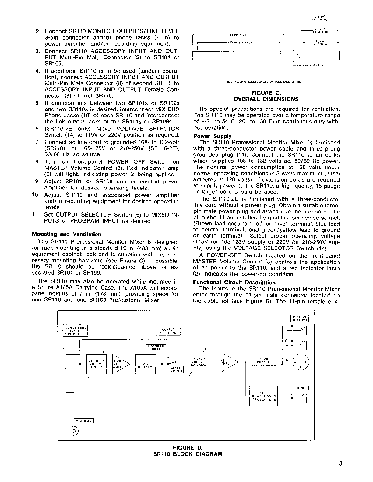
Functional Circuit Description
The inputs to the SRllO Professional Monitor Mixer
enter through the 11-pin
male connector located on
the cable (8) (see Figure D). The 11-pin female
con-
FIGURE D.
SR110 BLOCK DIAGRAM
INPUT
AND OUTPUT
\
/'
/
-24
08
HEADPHONES
TRANSFORMER
MASTER
VOLUME
CONTROL
-----C-
/
-1
DB
f
=
OUTPUT
TRANSFORMER
-
2
DB
MIX
RESISTOR
CHANNEL
I
DB
i
VOLUME -MIX
-
nector (9) is wired in parallel, and provides connection
for additional (tandem) SRllOs.
With the OUTPUT SELECTOR Switch (5) in the
MIXED INPUTS position, the input signals from the
individual channels of the
SR101 or SR109 go through
the individual channel Volume Controls
(I), a -1 dB
mixing amplifier, a -2 dB mixing resistor, and the
OUTPUT SELECTOR Switch before reaching the MASTER Volume Control
(3).
With the OUTPUT SELECTOR
Switch in the PROGRAM INPUT position, the program
input signal from the
SR101 or SR109 goes directly
through the OUTPUT SELECTOR Switch to the MASTER Volume Control. The MIX BUS Jack (10) is connected after the mixing resistor and before the OUTPUT SELECTOR Switch. The MIX BUS Jack is for
parallel operation of two or more
SR101 or SR1091
SRIIO
combinations, providing 16 inputs with the OUT-
PUT SELECTOR Switch in the MIXED INPUTS position.
From the MASTER Volume Control
(3),
the signal
enters a +42 dB amplifier stage. The amplifier output
is fed to both line level (-1 dB) and headphone
(-24 dB) output transformers. The line level transformer feeds a three-pin professional male audio connector
(7)
and two standard
1/4"
three-circuit (stereo)
phone jacks (6). The headphone transformer feeds a
standard
Y4
in. three-circuit (stereo) phone jack (4)
designed for use with 8 ohm stereo or monophonic
headphones.
Inputs and Outputs
All
SR110 inputs enter through the ACCESSORY INPUT AND OUTPUT 11-pin male connector (8). Pins 1
through 8 are the individual channel signals derived
from the eight
SR101 or SR109 channels (following the
equalizer circuits), pin 9 is a total program signal
(taken from the
SRlOl Monitor post link-pre link Switch
or
SR109 link input jack), pin 10 is the SR101 or SR109
+30 Vdc supply voltage and is not internally con-
nected to the
SR110 supply, and pin 11 is ground.
The ACCESSORY INPUT AND OUTPUT 11-pin fe-
male connector (9) is wired in parallel with the male
connector, and provides for connection of additional
(tandem)
SRll 0s.
The MONITOR OUTPUTSILINE LEVEL connectors
consists of one three-pin professional male audio connector
(7)
and two standard
VI
in. three-circuit (stereo)
phone jacks (6). These connectors provide three line
level, 600-ohm, balanced outputs to power amplifiers
or recording equipment.
The MIX BUS Phono Jack (10) provides a common
connection when two SRlOls or
SRIO9s and two or
more SRllOs are to be operated in a common mix
mode (16 channels). If more than two SRllOs are used
"Y" adapters can be used to connect the additional
MIX BUS Jacks.
The PHONES Jack
(4)
is a standard
1/4
in. threecircuit (stereo) phone jack designed for use with
8-ohm stereo or monophonic headphones.
Stage Monitor
To use the
SR110 as a stage monitor mixer (in con-
junction with the
SR101
or SR109), connect the ACCESSORY INPUT AND OUTPUT male connector (8) to
the
SRlO1 or SR109 ACCESSORY OUTPUTIAUX LEVEL
female connector (see Figure
E).
Turn up the individual
channel Volume Controls (1) to be monitored on stage;
turn the remaining channel Volume Controls to
0 (off).
With the OUTPUT SELECTOR Switch in the MIXED IN-
TO
ACCESSORY
INPUT TO
STAGE
SRlOl CONSOLE
I
OR
/
I
4ii~
I
SR109
MIXER
FIGURE E.
STAGE MONITOR CONNECTIONS
PUTS position and the MONITOR OUTPUTS connected
to the stage monitor power amplifier input, a separate
mix of inputs can be provided for stage monitoring.
The
SRI10 monitors the SR101 or SR109 individual
channels after the
SR101 or SR109 channel input at-
tenuator, volume and equalizer controls.
With the OUTPUT SELECTOR Switch in the PRO-
GRAM INPUT position the stage monitor has the same
mix as the
SRlO1 or SR109. The program outputs of the
SR101 or Sf3109 are used for the "house" PA system.
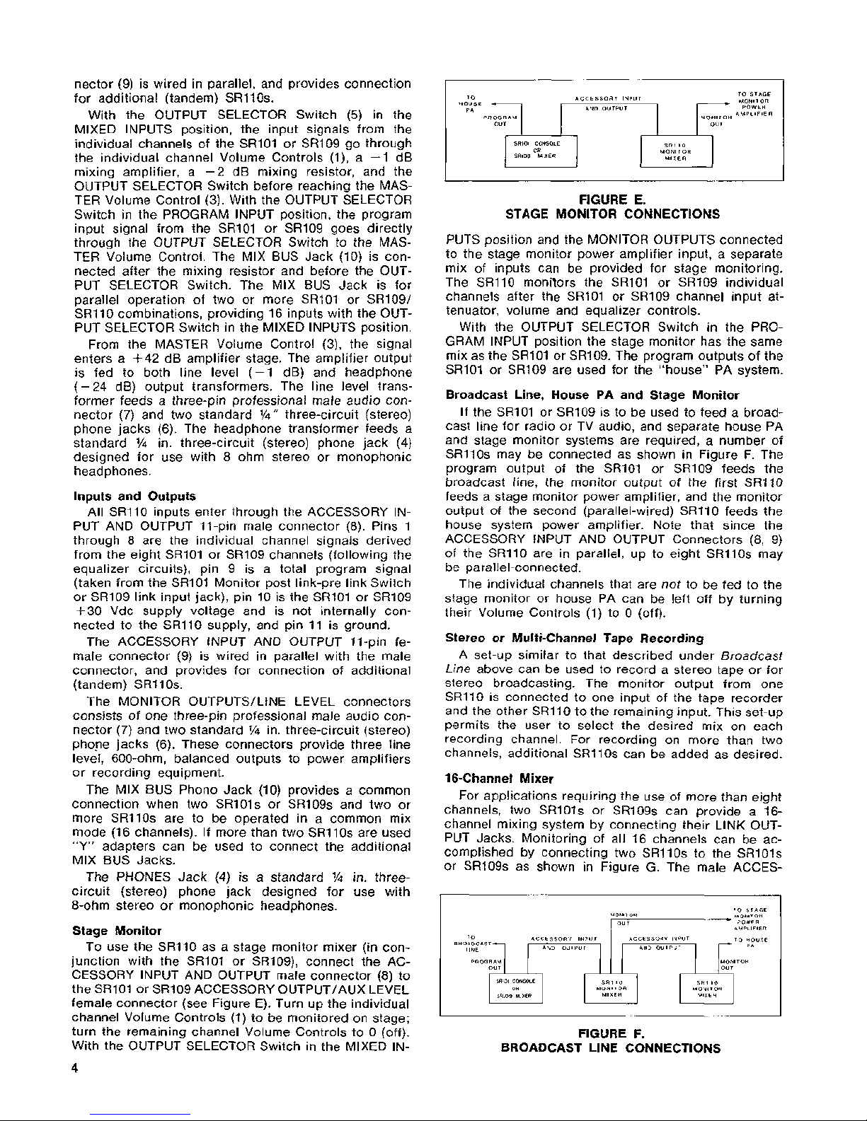
Broadcast Line, House PA and Stage Monitor
If the
SR101 or SR109 is to be used to feed a broadcast line for radio or TV audio, and separate house PA
and stage monitor systems are required, a number of
SRllOs may be connected as shown in Figure F. The
program output of the
SR101 or SR109 feeds the
broadcast line, the monitor output of the first
SR110
feeds a stage monitor power amplifier, and the monitor
output of the second (parallel-wired)
SR110 feeds the
house system power amplifier. Note that since the
ACCESSORY INPUT AND OUTPUT Connectors (8, 9)
of the
SR110 are in parallel, up to eight SRllOs may
be parallel-connected.
The individual channels that are not to be fed to the
stage monitor or house PA can be left off by turning
their Volume Controls (1) to
0 (off).
Stereo or Multi-Channel Tape Recording
A set-up similar to that described under Broadcast
Line
above can be used to record a stereo tape or for
stereo broadcasting. The monitor output from one
SR110 is connected to one input of the tape recorder
and the other
SR110 to the remaining input. This set-up
permits the user to select the desired mix on each
recording channel. For recording on more than two
channels, additional SRllOs can be added as desired.
16-Channel Mixer
For applications requiring the use of more than eight
channels, two SRlOls or
SRlO9s can provide a 16channel mixing system by connecting their LINK OUTPUT Jacks. Monitoring of all 16 channels can be accomplished by connecting two SRllOs to the SRlOls
or
SRlO9s as shown in Figure
G.
The male ACCES-
MONITOR
TO STAGE
MONITOR
OUT
POWER
AMPLIFIER
FIGURE
F.
BROADCAST LINE CONNECTIONS
 Loading...