

Shure SR101 Series 2 Operation And Service Manual
SRlOl
Series 2 Audio Console
OPERATION AND SERVICE MANUAL
Manufactured
by
SHURE BROTHERS INC.
222
Hartrey Avenue
Evanston, Illinois
60204
U.S.A.
Copyright 1979, Shure Brothers Inc.
27A1171
(SD)
(95E652)
Printed
in
U.S.A.
SR101 Series 2 Audio Console
SPECIFICATIONS
Equipment Type
Number of
lnput Channels
.
Power Output
. . .
.
Voltage Gain*
Program
. . . .
.
. . . .
All silicon transistor mixerlpre-
Hum and Noise
amplifier (20 Hz-20 kHz)
.
.....
8
.
. . . .
+19
dBm (program line level)
.73
k3 dB MIC input to LlNE
LEVEL out
. . . . .
.
-
125 dBV (equivalent input hum
and noise at full gain)
-
68 dBm output noise (MASTER
Volume Control down)
-
50 dBm output noise (one
channel Volume Control and
MASTER Volume Control up)
50
k3 dB AUX input to LlNE
LEVEL out
Signal to Noise Ratio
23 t3d~
MIC
input
to
MIC
LEVEL
(20 Hz-20 kHz)
.
.
. .
.Typically 81 dB at maximum out-
out
put with one channel Volume
Control and MASTER Volume
Monitor
. .
. . . .
. . .
.78 13 dB MIC input via PRO-
Control at 10 (approximately
GRAM MONITOR to LlNE
60 dB gain)
LEVEL out
65
k3 dB MIC input via PRO-
lnput Attenuation
. . . .
GRAM MONITOR to PHONES
out Input Clipping Level
87
23 dB MIC input via one chan-
at
kHz:
nel MONITOR to LINE LEVEL
MIC Input
. . . .
. .
out
Link
.
. . .
. . . . . . .
.
.38 _t3 dB MIC input to LlNK OUT
(with 600-ohm termination)
30
22
dB LlNK IN to LlNE LEVEL
out
Accessory
. .
. .
. . .
.48 t2 dB MIC input to ACCES-
SORY output (via pins
1-8lIN-
PUTS)
AUX Input
. . . .
. .
43 i.3 dB MIC inputs to ACCES-
SORY output (via pin
91PRO-
GRAM)
Frequency Response
. .
.
13 dB, 20 Hz-20 kHz (150-ohm
source; 600-ohm load)
lnput Sensitivity
. .
. .
. . .
0.4 mV max. for f 4 dBm program
output
Distortion
.
. . . . . . . . .
.
.
Noise
THD less than
1%
at +12 dBm,
Input Common
30 Hz -20 kHz; IM distortion
Mode
Rejection
. . .
.
less than 1% at t12 dBm
.
.O-30 dB (10 dB steps)
.
,315 mV (INPUT ATTEN at 0; Ch.
Volume at 2)
17.5
mV (INPUT ATTEN at 0; Ch.
Volume at 14)
10V (INPUT ATTEN at -30; Ch.
Volume at 2)
0.56V (INPUT ATTEN at -30; Ch.
Volume at 14)
.
.3.15V (INPUT ATTEN at 0; Ch.
Volume at 2)
0.18V (INPUT ATTEN at 0; Ch.
Volume at 14)
IOOV (INPUT ATTEN at -30; Ch.
Volume at 2)
5.6V (INPUT ATTEN at -30; Ch.
Volume at 14)
(300 Hz-20 kHz)
. .
. .
.
-
128 dBV(equiva1ent input noise
LOW-~requency
at full gain)
Equalization
. . .
. . .
-
78 dBm output noise (MASTER
Volume Control down)
-
53 dBm output noise (one
Hig h-Frequency
channel Volume Control and Equalization
. . .
. . .
MASTER Volume Control up)
100 dB min. at 100 Hz (balanced
inputs)
-;I3 dB at 100 Hz with respect to
0 (flat) setting
k12 dB at 10 kHz with respect to
0 (flat) setting
'Measurement conditions: MIC input through
150
ohms, AUX input through
33
kilohms LlNK IN through
600
ohms PROGRAM LlNE LEVEL and MONITOR
LlNE
LEVEL
terminated In
600
O~~~.'PROGRAM MIC LEVEL terminated in
150
ohms. MONITOR PHONES terminated in 8 ohms: MASTER Volume. Channel
~olur;le and MONITOR Controls full up; all other controls and switches 0 or off.
SR101 Series 2 Audio Console
SPECIFICATIONS
...
Feedback Filter VU Meter Calibration
$4 dBm (1.23 Vrms) at 1 kHz to
.......
Frequencies
.I30 Hz; 800 Hz; 2 kHz; 5 kHz
600-ohm load (METER
SENSI-
Tone Oscillator
........
1 kHz; less than 1% distortion;
variable level
lnput Impedance
at 1 kHz:
Microphone
.....
.1.2 kilohms balanced (for use
with 25- to 600-ohm'
micro-
Auxiliary
(Channels
7
phones)
........
and 8). .I70 kilohms unbalanced
.......
Link Input .35 kilohms unbalanced
Output Impedances:
Program
.........
Balanced line level: 120 ohms
actual (for use with 600-ohm
lines)
Microphone level: 0.5 ohms actual
(for use with 25- to 600-ohm inputs)
Monitor
.........
.Unbalanced line level: 600 ohms
actual (for use with 600-ohm or
high-impedance phones, or
600-ohm lines)
Headphones: 3 ohms
actual (for
use with 4- to 16-ohm headphones)
ACCESSORY AUX LEVEL
(unbalanced) pins 1-811NPUTS: 33
ohms
actual (for use with 3-
kilohm
or greater loads); pin 91
PROGRAM: 600 ohms actual
Link Output
......
.600 ohms (actual)
Monitor System
.......
Headphone andlor 600-ohm line
output; individual and mixed
channel select or program; preand post-link monitoring
Reverberation
System
.............
Spring type with individual chan-
nel
intensity controls and high-
and low-frequency equalization
Link Jack System
......
External signal conditioning out-
putlinput;
high-level auxiliary
amplifier and tape recorder
signal output;
multiple Console
connection (mix bus); remote
master volume
control
TlVlTY ~ontrol'in
CAL position)
[22 dB-range METER SENSITIVITY
Control in full clockwise
position provides 0 VU reading
of -18
dBm (0.1 Vrms) on 600ohm load]
....
Phasing (polarity).
.AUX LEVEL input and LINK IN
tips and pin 3 of INPUT con-
nectors in phase with pin 9 of
ACCESSORY OUTPUT; tips of
LlNK OUT, PROGRAM LlNE
LEVEL, and MONITOR LlNE
LEVEL outputs; tip of PHONES
jack; and pin 3 of PROGRAM
LlNE and MIC LEVEL outputs.
(PHASE Switch in 0" position.)
Pins 1-8 of ACCESSORY OUTPUT out of phase with the
above.
.........
Phase Switch Output polarity-reversing switch
(0°, 180°) (reverses phase of all
program outputs)
30 Vdc Bus
..........
.Pin 10 on ACCESSORY
AUX
LEVEL connector is regulated
+30
~3.5 Vdc supply; pin 11 is
ground (earth). May be used to
power accessories with up to
50
mA.
Operating Voltage
....
.90-132 Vac, 50160 Hz (SR101)
90-132, 180-250 Vac, 50160 Hz
(SR101-2E)
Power Consumption
...
20 watts max. (Console only). 500
watts max. (SWITCHED A.
C.
receptacle)
Temperature Range:
Operating
..........
-7' to 54OC (20' to 130°F)
Storage
............
-29' to 71°C (-20' to 160°F)
Dimensions
..........
.311 mm x 483 mm x 162 mm
(121/'"
H x 19" W x 6%''
D)
Installation
...........
Equipped for standard 19" rack
mounting
(12%" height); may
be operated in accessory
AlOlA Carrying Case or in custom control center
Weight
..............
.22 Ib (10 kg)
Finish
................
Matte black, with beige write-on
trim strip
Certifications
.........
Listed by Underwriters' Labora-
tories, Inc.; listed by Canadian
Standards Association as certified
(SRIOI only)
iii
SR101 Series 2 Audio Console
TABLE OF CONTENTS
Section Page
SPECIFICATIONS ii
DESCRIPTION
OPERATING INSTRUCTIONS
Functional Identification
General Operating Instructions
Mounting and Ventilation
Power Supply
Functional Circuit Description
Input Channels
Source Cuing 7
Reverberation
Monitor System
Monitor Mixer System
Program Mix Amplifier
Link Jacks
Feedback Filters
Program Output
VU Meter Circuit
Tone Oscillator
Basic Operating Hints
SPECIAL OPERATING INSTRUCTIONS
High-Impedance Microphones
Musical Instruments
Tape Recording
Record Playback
Tape Playback
Talkback Circuit
Additional Mixer Inputs
..............................
.................................
.......................
.................
......................
................................
..................
..............................
1
3
3
4
5
5
7
................................
................................
..............................
.........................
.......................
..................................
.............................
.............................
............................
..............................
........................
.................
..........................
.............................
.............................
...............................
..............................
........................
7
8
8
9
9
9
9
10
10
11
11
11
12
12
12
13
13
Section Page
Additional Console Inputs (Two Consoles)
Redundant Console Set-up (Two Consoles) 15
Stereo Operation 16
Remote Volume Control 17
Telephone Line Surge Protection 17
SERVICE INSTRUCTIONS
Console Service 18
Replacement Parts 18
Fuse Replacement 18
Knob Replacement
ServiceAccess 18
Lamp Replacement 18
Reverberation Assembly
Board Removal
VU Meter Removal
VU Meter Calibration
Volume Control Assembly
Parts Removal
Transistor and Diode Removal
Transistor and Diode Checking
Service Illustrations
Optional Accessories
Guarantee
Shipping Instructions
PARTS
CONDENSED OPERATING INSTRUCTIONS
ARCHITECTS' AND ENGINEERS'
SPECIFICATIONS 47
...................................
LIST
...................................
............................
.......................
..............
..............................
............................
............................
...........................
...............................
...........................
....................... 18
...............................
............................
..........................
.....................
...............................
.................
.................
...........................
..........................
.........................
............................
........
.......
........
14
18
18
20
20
20
21
22
22
22
22
22
22
23
47
SR101
Figure Page
1 SR101 Audio Console Front Panel ........... 2
SR101 Audio Console Rear Panel
2
SRlO1 Audio Console Dimensional
3
Outline Drawing
SR101 Audio Console Block Diagram
4
5 Monitor Mixer Applications
6 Tone Oscillator Applications
7 Preamplifier-Console Connnections
8 Tape Recording
9 Record Playback 13
Talkbackcircuit
10
11 Carbon Microphone Power Supply
12 Additional Mixer Inputs
13 Additional Inputs: Two Consoles
14 Redundant Consoles
15 Stereo Tape Recording
.........................
..........................
........................
..........................
....................
......................
...................
Series 2 Audio Console
LlST
............
................
...............
OF
ILLUSTRATIONS
........
.........
..........
..........
Figure Page
...................
..................
.....................
..............
...............
.............
..............
..................
.................
...........
.........................
....................
....................
....................
...................
2
5
6
9
10
11
12
13
13
14
15
16
17
16 Remote Volume Control 17
17 Printed Circuit Board and Parts Location 19
18 Volume Control Assembly
19 Board 1: Preamplifier
20 Board 2A: Channel Equalizer
21 Board
22 Board 3: Program Mix Amplifier
23 Board 4: Reverb Mix Amplifier
24 Board 5: Program Output
25
26 Board 7: Reverb Spring Amplifier
27 Board 8: Monitor
28 Board 9: Power Supply
29 Board
30 Transistor Lead Codes
31
32 Circuit Diagram
28: Reverb Equalizer
Board 6: Feedback Filters
0: Program Mute
SR101-2E Power Supply
........................
.....
21
33
34
34
35
35
36
37
37
38
38
39
41
42
.4 4-45
SRIOI Series 2 Audio Console
DESCRIPTION
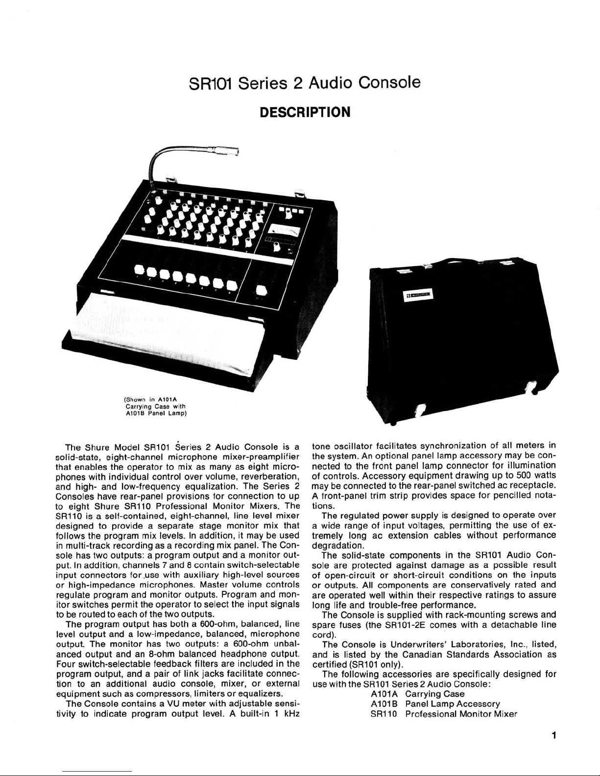
(Shown
in
AIOIA
Carrying Case
with
AlOlB
Panel Lamp)
The Shure Model SR101 series 2 Audio Console is a
solid-state, eight-channel microphone mixer-preamplifier
that enables the operator to mix as many as eight microphones with individual control over volume, reverberation,
and high- and low-frequency equalization. The Series 2
Consoles have rear-panel provisions for connection to up
to eight Shure
SR110 Professional Monitor Mixers. The
SR110 is a self-contained, eight-channel, line level mixer
designed to provide a separate stage monitor mix that
follows the program mix levels. In addition, it may be used
in multi-track recording as a recording mix panel. The Console has two outputs: a program output and a monitor output. In addition, channels
7
and 8 contain switch-selectable
input connectors for .use with auxiliary high-level sources
or high-impedance microphones. Master volume controls
regulate program and monitor outputs. Program and monitor switches permit the operator to select the input signals
to be routed to each of the two outputs.
The program output has both a 600-ohm, balanced, line
level output and a low-impedance, balanced, microphone
output. The monitor has two outputs: a 600-ohm unbalanced output and an 8-ohm balanced headphone output.
Four switch-selectable feedback filters are included in the
program output, and a pair of link jacks facilitate connection to an additional audio console, mixer, or external
equipment such as compressors, limiters or equalizers.
The Console contains a VU meter with adjustable sensitivity to indicate program output level. A built-in 1 kHz
tone oscillator facilitates synchronization of all meters in
the system. An optional panel lamp accessory may be connected to the front panel lamp connector for illumination
of controls. Accessory equipment drawing up to 500 watts
may be connected to the rear-panel switched ac receptacle.
A front-panel trim strip provides space for pencilled notations.
The regulated power supply is designed to operate over
a wide range of input voltages, permitting the use of extremely long ac extension cables without performance
degradation.
The solid-state components in the
SR101 Audio Console are protected against damage as a possible result
of open-circuit or short-circuit conditions on the inputs
or outputs. All components are conservatively rated and
are operated well within their respective ratings to assure
long life and trouble-free performance.
The Console is supplied with rack-mounting screws and
spare fuses (the
SRlOI-2E comes with a detachable line
cord).
The Console is Underwriters' Laboratories,
Inc., listed,
and is listed by the Canadian Standards Association as
certified
(SRI 01 only).
The following accessories are specifically designed for
use with the
SRlOl Series 2 Audio Console:
AlOlA Carrying Case
A101 B Panel Lamp Accessory
SR110 Professional Monitor Mixer
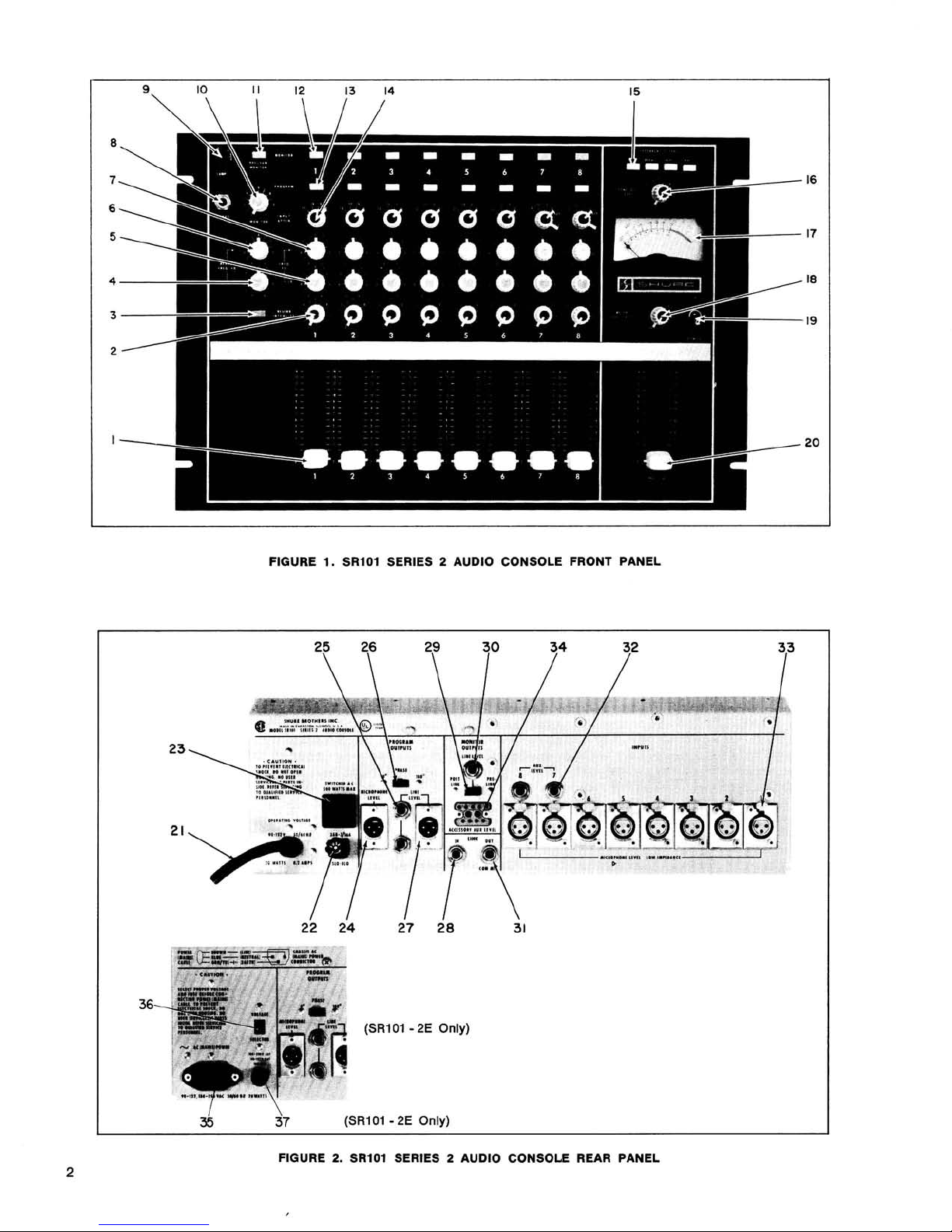
FIGURE 1. SRlOl SERIES 2 AUDIO CONSOLE FRONT PANEL
36
25
26
(SR101
-
29
2E
Only)
30
34
32
3
3
35
37
FIGURE
2
(SR101 - 2E
2.
SRlOl SERIES 2 AUDIO CONSOLE REAR PANEL
Only)
SR101
Series 2 Audio Console
OPERATING INSTRUCTIONS
FUNCTIONAL IDENTIFICATION (Refer to Figures 1 and
2, Page 2.)
NOTE: All push-button switches are "on" when in (depressed) and "off" when out (released). Input attenuator
switches are calibrated in decibels; all other front panel
controls are numbered for reference only.
1. lndividual Channel Volume Slide Controls (Eight)
-
Control volume and input clipping level of each channel separately.
2. REVERB INTENSITY Rotary Controls (Eight)
-
Con-
trol reverb level for each channel.
3. Master REVERB Push-Button Switch -Turns on (or
off) amount of reverb preset by channel REVERB IN-
TENSITY controls.
4. REVERB FREQuency
EQualizer-LOW Rotary Control
-
Adjusts low-frequency reverb signal equalization.
5.
lndividual Channel FREQuency EQualizer-LOW Rotary
Controls (Eight)
-
Adjust low-frequency signal equal-
ization for each channel.
6. REVERB FREQuency
EQualizer-Hlgh Rotary Control
-
Adjusts high-frequency reverb signal equalization.
7. lndividual Channel FREQuency
EQualization-Hlgh Ro-
tary Control (Eight)
-
Adjusts high-frequency signal
equalization for each channel.
8. PHONES Output Jack
-
Provides for connection of
stereo or monophonic headphones for monitoring.
9. Panel LAMP Accessory Connector
-
Provides connection for optional panel lamp accessory to illuminate front panel.
10. MONITOR Level Rotary Control
-
Controls volume
level to PHONES Jack (8) and MONITOR OUTPUT/
LlNE LEVEL Jack (30).
11. PROGRAM MONITOR Push-Button Switch
-
Connects total program output (all channels and reverb)
to PHONES Jack (8) and MONITOR
OUTPUT/LINE
LEVEL Jack (30).
12. lndividual Channel MONITOR Push-Button Switches
(Eight)
-
Connect individual channel outputs (with-
out reverb) to PHONES Jack (8) and MONITOR
OUT-
PUT/LINE
LEVEL Jack (30) when PROGRAM MON-
ITOR Switch (11) is off.
13. lndividual Channel PROGRAM Push-Button Switches
(Eight)
-
Connect individual channel inputs to pro-
gram output.
14. lndividual Channel INPUT
ATTENuator Rotary
Switches (Eight)
-
Provide choice of input signal attenuation for each channel. Dual switches on channels
7
and 8 also select low-impedance (MIC) or high-
impedance (AUX) input connections.
15. FEEDBACK FILTERS Push-Button Switches (Four)
-
Provide for elimination of acoustic feedback in four
most probable audio frequency ranges.
16. TONE
Oscillator LEVEL SwitchIRotary Control
-
Turns on and adjusts level of 1
kHz
tone generated
internally for set-up purposes.
17. True VU Meter
-
Indicates volume level of program
output. (Meets all current standards for VU Meters).
18. METER SENSITIVITY Rotary Control
-
Adjusts VU
meter sensitivity for wide ranges of program level
indication.
19.
POWER ON-OFF Toggle Switch - Applies ac power
to power supply and SWITCHED A.C. Receptacle (23).
20. MASTER Volume Slide Control
-
Adjusts level of total
program output.
21. Ac Grounded Line Cord
-
Connects ac power source
to Console power supply
(SRlO1 only).
22.
3AG-3/16A SLO-BLO Ac Fuse - Protects Console ac
input line against overload
(SRlOl only).
23. SWITCHED A. C. Grounded Receptacle
-
Provides up
to 500 watts of switched ac power to accessory equipment
iSR101 only).
24.
PROGRAM OUTPUTSIMICrophone LEVEL 3-Pin Connector
-
Provides low-impedance microphone-level
program output.
25. PROGRAM
OUTPUTS/LINE LEVEL Phone Jacks
(Two)
-
Provide balanced or unbalanced output con-
nections to power amplifier.
26. PROGRAM
OUTPUTS/PHASE Slide Switch - Re-
verses phase (polarity) of
LlNE LEVEL and MIC LEVEL
program outputs with respect to inputs.
27. PROGRAM
OUTPUTSILINE LEVEL 3-Pin Connector
-
Provides balanced output connection to power
amplifier.
28. LlNK IN Phone Jack- Provides input connection for
external equipment (compressor, limiter, equalizer,
etc.).
29. MONITOR
OUTPUTIPOST LINK-PRE LlNK Slide
Switch
-
Selects program monitoring either before or
after external equipment connection to LlNK Jacks (28,
31).
30. MONITOR
OUTPUTILINE LEVEL Phone Jack - Pro-
vides monitor output connection to power amplifier.
31. LlNK OUT Phone Jack
-
Provides output connection
for external equipment, or mix bus to add Consoles.
32.
INPUTS/AUX. LEVEL Phone Jacks (Two) - Provide
for connection of high-impedance sources to channel
7
or 8 inputs.
33. INPUTS/ MICROPHONE LEVEL 3-Pin Jacks (Eight)
-
Provide for balanced connection of low-impedance
sources to channels 1 through 8 inputs.
34. ACCESSORY AUX LEVEL
1 I-Pin Connector-Provides
output connection to Shure
SR110 Monitor Mixer.
35. AC (MAINS) POWER 3-Pin Connector-Connects ac
power cable to Console power supply
(SRlOl-2E only).
36. VOLTAGE SELECTOR Slide Switch-Selects operating voltage range of 90 to 132 or 180 to 250
Vac,
50/60
Hz (SRIOI-2E only).
37. 180-250V 0.1
AT/90-132V 0.2AT Ac Fuse-Protects
Console ac input line against overload
(SR101-2E
only).
GENERAL OPERATING INSTRUCTIONS
WARNING
Voltages in this equipment are hazardous to life. Make
all input and output connections with ac power disconnected. Refer servicing to qualified service personnel.
1. Using hardware provided, install Console securely in
standard
19" (483 mm) rack or optional AlOIA Carrying Case prior to making electrical connections. For
custom installations, see mounting template supplied
with Console. If desired, connect
AlOlB Panel Lamp
Accessory to LAMP Connector (9).
3
2. Set all front-panel switches to off (out) and all controls to
0. Set rear-panel PHASE Switch (26) to 0'.
3. Connect desired PROGRAM OUTPUT/LINE LEVEL
Connector
(25,27) to power amplifier input connect-
ing cable. (NOTE: Shure
SR105 Power Amplifiers
are supplied with audio connecting cables.) If Console
output is to be fed to another mixer or tape recorder
microphone input, use PROGRAM
OUTPUT/MIC
LEVEL Connector (24). If desired, connect monophonic or stereo headphones to front-panel PHONES
Jack (8). Connect speakers to power amplifier.
4. Connect one or more low-impedance microphones to
rear-panel
INPUTS/MICROPHONE LEVEL Connector
(33). Any high-quality dynamic, ribbon or condenser
low-impedance microphone may be used. Connect
high-impedance microphones or auxiliary high-level
sources to
INPUTS/AUX. LEVEL Connectors (32) in
channels 7 or 8 only. If AUX. LEVEL Connectors are
used, set corresponding front-panel
MIC/AUX (INPUT
ATTEN) Switch (14) to AUX.
5. If external signal-processing equipment such as an
equalizer, compressor or limiter is to be used, connect Console
LlNK OUT Connector (31) to external
equipment input and Console
LlNK IN Connector (28)
to external equipment output. (See Link Jacks, Page
8,
for detailed information.)
6.
SR101: Connect ac line cord (21) to grounded 90- to
132-volt,
50/60 Hz ac source.
Line cord
is
a 2.44m (8-ft.), 3-conductor cord with
3-pin grounding plug. If extension cords are required,
use high-quality, rubber-jacketed cable with 18 gauge
or larger wire.
SRlOl-2E: Obtain suitable &pin male ac connector
and attach to line cord: brown lead to "hot" or "live"
terminal,
blue lead to neutral terminal, and green/
yellow lead to ground or earth terminal. (Connector
should be installed by qualified service personnel.)
Select proper operating voltage (90-132V or
180-
250V)
using VOLTAGE SELECTOR Switch (36). Note
that switch positions are marked 115 and 220 volts.
Make certain proper fuse is installed in fuseholder
(37):
O.1AT with switch set to 220, or 0.2AT with
switch set to 115. Insert female end of line cord into
chassis power connector (35) and connect male plug
to 3-wire grounded ac power receptacle providing
proper operating voltage.
7. Turn on front-panel POWER Switch (19) and allow
one to two minutes
warmup time. This warmup time
allows the supply voltages to stabilize and capacitors
to charge to provide optimum performance. Depress
PROGRAM Switch (13) for channel to be used. (IMPORTANT: No program output will result if this switch
is not depressed!) Set INPUT
ATTEN Control (14) for
that channel initially to
0 for normal or PA use, to -10
for instrumental music, or to -20 or -30 for "hard"
rock music. For AUX. INPUT sources (channels 7 and
8), set INPUT ATTEN Control initially to -20 or -30.
8.
Set MASTER Volume Control (20) to 7. Set METER
SENSITIVITY Control (18) to CAL position. Have someone sing or talk into microphone and raise channel
Volume Control (1) to achieve desired sound level. If
VU Meter (17) reads too low at proper sound level, increase METER SENSITIVITY Control until normal meter movement
-
operation in black area of scale with
occasional peak excursions into red area
-
is ob-
tained. If meter still reads low, reduce power amplifier
volume level and increase channel volume level. For
single microphone set-up, if meter indicates excessively high level ("pinning" or "pegging" needle),
decrease channel Volume Control to obtain good
meter reading and increase power amplifier volume
level or input sensitivity to obtain proper sound level.
In multiple microphone set-up, it may be necessary
to
decrease MASTER Volume Control in order to maintain channel Volume Control setting. Ideally, channel
Volume Control should remain approximately at mid-
range (7-9) to facilitate increases or decreases in con-
trol setting due to program change; INPUT
ATTEN
Control (14) adjustment will aid in maintaining this setting. If feedback occurs below desired sound level,
consult section on Feedback
Filters
(Page 8).
9. Set HI and LO FREQ EQ Controls (7,5) for channel in
use. Vertical position
(0) indicates "flat" frequency re-
sponse. Clockwise
(+)
settings increase high-fre-
quency (treble) or low-frequency (bass) equalization
and counterclockwise
(-)
settings decrease frequency equalization. Note that these controls also
affect feedback; readjustment of Feedback Filters (15)
may be necessary.
10. If reverberation is desired, depress REVERB Switch
(3) and adjust REVERB INTENSITY Control (2) to
desired level for channel in use. Recommended settings are: speech
-
0, vocals - 3-6, instruments
-
5-10. Adjust HI and LO REVERB FREQ EQ Controls
(6,4) for desired frequency equalization.
11. To monitor channel in use, depress MONITOR Switch
(12) for that channel. Monitor output is available at
front-panel PHONES Jack (8) and rear-panel MONITOR
OUTPUT/LINE LEVEL Jack (30). Adjust MONI-
TOR Control (10) for comfortable listening level. Note
that any or all channels may be monitored whether or
not PROGRAM Switch (13) for that channel is de-
pressed; merely depress MONITOR Switch for desired
channel. When total program output monitoring is desired, depress PROGRAM MONITOR Switch (11). Note
too that only those channels with PROGRAM Switch
(13) depressed will be heard while monitoring with
PROGRAM MONITOR Switch depressed.
12. NOTE: During temporary shutdown (break, intermission), it is not necessary to turn off Console power. It
is designed to operate continuously, and optimum performance is maintained after internal voltages are allowed to stabilize. Also, do not turn off all microphones.
Leave the master or announcer's microphone on (PROGRAM Switch depressed) so that
if
the Console is left
unattended, announcements may be made, and the
Console operator will be alerted that the next performance is about to begin.
MOUNTING AND VENTILATION
The Shure
SR101 Audio Console may be operated in a
standard 19" (483 mm) audio equipment rack, in a Shure
AlOlA Carrying Case, or custom-mounted in a table- or
desk-type control center. Four rack-mounting screws are
provided with the Console. These screws may also be used
if the Console is to be custom-mounted in a metal-top control center.
A custom-mounting template is supplied with the Console. Cutting dimensions and drill hole locations are given,
as are clearances for insertion and ventilation. The
dimen-
sions given should be followed to provide adequate cable
clearance (see Figure 3, Page 5).
In either rack- or custom-mounted installations, consider
rear-panel access before installation is made. Although
most installations will not require frequent access, it should
be remembered that input and output changes, and some
switch movements, will necessitate rear-panel access. Rear
panels are most easily reached in standard audio racks or
in custom installations having bottom access, such as an
open desk or a lower control center access panel.
,
.
NOTE: CLEARANCE DIMENSIONS
I
SHOWN. SEE MOUNTING
TEMPLATE.
I
I
I
I
*
NOT INCLUDING CONNECTOR/CABLE CLEARANCE
DEPTH.
I
-
--
-
FIGURE
3.
SRlOl AUDIO CONSOLE
DIMENSIONAL OUTLINE DRAWING
POWER SUPPLY
SR101: The SR101 regulated power supply is designed to
operate from 90 to 132 volts ac,
50/60 Hz without adjustments, allowing the Console to meet all specifications over
this wide range of ac input voltages. A three-conductor,
grounded line cord (21) supplies ac power to the Console
through the front-panel POWER ON-OFF Switch (19). The
Console consumes 20 watts maximum (0.2 amperes) and
the ac line input is protected by a
3/16-ampere slo-blo fuse
(22) and a wired-in
3/10-ampere slo-blo fuse in series. A
wired-in 1-ampere slo-blo fuse protects the 5.6-volt secondary winding (indicator lamp) of the power transformer.
CAUTION
These fuses should not be replaced with any
other size or type of fuse.
Accessory equipment may be connected to the
rear-
panel SWITCHED A.C.
Receptacle (23). The accessory
equipment may consume up to 500 watts maximum, which
provides for use with high-power amplifiers such as the
Shure
SR105. Note that the receptacle is switched but not
fused; all accessory equipment used with the Console
should contain its own fuse.
SR101-2E: The SR101-2E regulated power supply is designed to operate from either 90 to 132 volts ac or 180 to
250 volts ac,
50/60 Hz, as selected by the rear-panel VOLTAGE SELECTOR Switch (36). A three-conductor, grounded
line cord supplies ac power to the Console through the
front-panel POWER ON-OFF Switch (19). The
SR101-2E
line cord does not have a connector on the power source
end of the cord. Obtain a suitable three-pin male ac connector and install it on the line cord: brown to "hot" or
"live" terminal, blue lead to neutral terminal, and green/
yellow lead to ground or earth terminal. (Connector should
be installed by qualified service personnel.) The ac line is
protected by a 0.1-ampere Slo-Blo fuse (for 180- to 250-volt
operation) or a 0.2-ampere Slo-Blo fuse (for 90- to 132-volt
operation). Wired-in
3/10- and 1-ampere fuses protect the
ac line and power transformer 5.6-volt secondary winding,
respectively.
FUNCTIONAL CIRCUIT DESCRIPTION
(See Figure 4, Page 6)
Each 3-pin professional audio input Microphone Connector (33) feeds its own low-impedance lnput Transformer,
which provides a gain increase of 23 dB. Channels
7
and 8
also contain switchable AUX LEVEL phone jacks (32) which
accept high-impedance microphones or other inputs. The
lnput Transformers (and, on channels
7
and 8, the AUX-
MIC Switch) are fed to 0-30 dB INPUT ATTEN Controls (14)
and then to the Preamplifier, which provides a
A6 to $30
dB gain increase. The amount of gain provided by the Preamplifier (6 to 30 dB) is controlled by the Channel Volume
Control
(I), providing an increase in input clipping level as
gain is reduced. The Preamplifier circuits contain the individual Channel Volume Controls and feed the individual
Channel Equalizer (HI and LO FREQ EQ) Controls
(73)
which decrease the signal approximately 2 dB when set to
the 0, or "flat," setting.
The Equalizer outputs go to the Program and Monitor
circuits, and to the ACCESSORY AUX LEVEL Connector
(34) for interconnection with
SR110 Monitor Mixers. The
Channel Equalizer outputs going to the Program circuits
go first to the individual channel PROGRAM Switch
(13),
and subsequently to the Reverb circuits and individual
channel REVERB INTENSITY Controls (2). When reverb is
not used, the REVERB INTENSITY Control is set to 0, and
the channel output is sent directly to the Program Mix
Amplifier. When reverb is employed
-
REVERB Switch (3)
depressed
-
the REVERB INTENSITY Control feeds the
Reverb Intensity Mix Amplifier, Reverb Equalizer, Reverb
Driver and Differential Amplifiers, Reverb Output Mix Amplifier, and then into the Program Mix Amplifier. Note that as
the control is increased the amount of non-reverb ("dry")
signal sent to the Program Mix Amplifier is reduced, while
the signal sent to the Reverb lntensity Mix Amplifier is
increased.
The Channel Equalizer output to the Monitor input, con-
trolled for each channel by a MONITOR Switch
(12), is fed
to the Monitor Mix Amplifier, which changes the input by
+3 to -13 dB. The Amplifier output goes to the PROGRAM
MONITOR Switch (1
I), where it may be selected to continue
through the MONITOR Level Control
(lo), +40 dB Monitor
Amplifier, and to the rear-panel MONITOR
OUTPUT/LINE
LEVEL jack (30) and front-panel PHONES jack (8).
The Program Mix Amplifier goes to both the PRE LlNK
side of the POST
LINK/PRE LlNK Switch (29) for routing to
the Monitor circuits, and through a 560-ohm resistor to the
LlNK jacks
(28,31). When accessory equipment is not connected to the LlNK jacks, the jacks are bypassed and the
program signal is fed to the POST LlNK side of the POST
LINK/PRE LINK Switch for monitoring, and to the MASTER
Volume Control (20). Note that the PRE
LINK/POST LlNK
Switch output to the Monitor circuits is also routed to the
ACCESSORY AUX LEVEL Connector (34).
The output of the MASTER Volume Control, after feeding
a
0 dB gain Amplifier, is sent through a bank of four select-
able FEEDBACK FILTERS
(15), which provide attenuation
at 130, 800, 2000 and 5000 Hz for feedback control. The
FEEDBACK FILTERS output goes to a
+6 to +31 dB
Amplifier, also controlled by the MASTER Volume Control,
through a
180' PHASE Switch (26), and into the Program
NOTE
(
TYPICAL OF CHANNELS 1-8
l
1
lMlCROPHONE LEVEL
200
HIGH
X~~~
1+23 dB1
mn
-
RESISTOR
I
n:
-
0-30 dB CHANNEL
,
INPUT
-
ITTEN
TONE
OSC
LEVEL
/
f
-
VOLUME - CHANNEL
(SECTION
/I
I
,
CHANNEL REVERB
VOLUME
(SECTION
/
-2
dB REVERB
A)
EWALIZER
P
0) (SECTION A)
I
pimq
OUT
-
4-
IN (SECTION 0)
FEEDBACK
FILTERS]
-
-
INTENSITY
/
I
I
I
INTENSITY
/
f
-
f
(SECTION
NOTES: I. AUX. LEVEL INPUT AND AUX-MIC SWITCH
ON CHANNELS
7
AND 8 ONLY.
FlGUR,E
4.
[PHASE]
m-
MASTER
VOLUME
.
8)
MON
-
LEVEL
/
1-10 dB1
SRlOl SERIES 2 CONSOLE BLOCK DIAGRAM
PROGRAM OUTPUTS
LEVEL

Output Transformer. The Transformer feeds three LlNE
LEVEL Output Connectors (25,27) and a MIC LEVEL Output Connector
(24), which is at
50
dB below line level. The
+6
to $-31 dB Amplifier also feeds the METER SENSITIVITY Control (18), which goes to a +22 dB Meter Amplifier,
and then to the VU Meter (17).
The Console also contains a 1
kHz Tone Generator for
use in set-up and checkout. The Generator is activated and
controlled by the TONE OSC LEVEL
SwitchIControl (16),
and the control output is fed to the Program Mix Amplifier.
A detailed description of the Console circuits and controls and their uses is provided in the following paragraphs
of this section.
INPUT CHANNELS
Eight professional, three-pin, audio MICROPHONE
LEVEL lnput Connectors (33) are provided on the upper
rear panel of the Console. The Console is designed to operate with high-quality, low-impedance dynamic, ribbon or
condenser microphones. Two additional AUX. LEVEL Input Connectors (32) are provided for channels
7
and
8.
These standard quarter-inch phone jacks allow connection
to auxiliary high-level sources or high-impedance microphones. Switches on the channels 7 and
8
INPUT ATTEN
Control (14) allow the user to select between either the
low-impedance microphone input (MIC), or the
high-impedance auxiliary input (AUX). Each low-impedance microphone input is connected to a low-impedance, balancedinput transformer, the output of which is connected to a
0-30 dB input attenuator. On channels 7 and
8,
the outputs
of the low-impedance microphone transformer and the
AUX. LEVEL lnput Jack (32) terminate in the AUX-MIC
Switch. The output of this switch goes to the 0-30 dB INPUT
ATTEN Switch (14). Note that the AUX-MIC Switch has
two detented positions; no output will be obtained when
the switch is between detent positions. The MIC-AUX
Switch grounds the unselected input to reduce crosstalk.
This should be considered when connecting inputs to this
channel. A
I-kilohm isolation resistor is provided in the
AUX input circuit. When the AUX input is not selected, this
resistor is grounded, placing the
I-kilohm load on the AUX
input. If the source connected to this input is also bridged
to feed other inputs, an additional isolation resistor may be
required.
The INPUT
ATTEN (14) four-position switch provides
input attenuations of 0, 10, 20, or 30 dB. This switch allows
the user to compensate for the differences in levels due to
different sources, such as close talking or distant microphone placement, and to compensate for high output levels
from condenser microphones.
The Channel Volume Control (1) is a dual control: one
section, in a feedback circuit, sets the gain of the preamplifier, and the second section is a preamplifier output
attenu-
ator.
This circuit configuration increases the preamplifier
input clipping level as the Volume Control is reduced to
lower settings. Ideally, the control should operate in the
middle range, between 7 and
9.
This can generally be ac-
complished by proper INPUT
ATTEN Control (14) setting.
The output of the Channel Volume Control (1) feeds the
equalizer circuit. Individual HI and LO FREQ EQ controls
(7,5)
allow the user to shape the sound of each input
channel without affecting the other channels on the Console. The HI FREQ controls provide up to 13 dB of boost
or cut at 10 kHz with a 1 kHz hinge point. The LO FREQ
controls provide up to 13 dB of boost or cut at 100 Hz with
a 1 kHz hinge point. Control settings with plus
(+)
markings
indicate boost, and minus
(-)
markings denote cut. A 0
setting provides a normal or "flat" frequency response.
The output of the equalizer feeds the channel PROGRAM
and MONITOR Switches
(13,12). The PROGRAM Switch
selects the channels to be connected to the program out-
put. The MONITOR switches select the channels to be connected to the monitor output. The two switches are independent and have no effect on each other.
SOURCE CUING
Microphones, tape recorders, or other sources may be
preset, or cued, during a performance in the following
manner. With
headphones connected to the front-panel
PHONES Jack (8) or rear-panel
MONITOR
LlNE LEVEL
Jack (30) (high-impedance headphones only), depress the
PROGRAM MONITOR Switch (11) and a PROGRAM Switch
(13) for a channel that has program material at the proper
level on it. Adjust the MONITOR Level Control (10) until an
adequate audio level is heard in the headphones. Release
the PROGRAM MONITOR Switch and PROGRAM Switch
for that channel, and depress the MONITOR Switch (12) for
the channel being cued. With the MONITOR Level Control
previously set, raise the channel Volume Control (1) until
the same audio level heard in the other PROGRAM channel
has been reached.
With the channel PROGRAM Switch (13) released and
the channel MONITOR Switch (12) depressed, the source
will be heard on the headphones and not on the program
channel. This allows the Console operator to cue up tapes,
check out microphones, etc., without interfering with the
program. When the channel is to be activated, depress the
channel PROGRAM Switch.
It is most important to have a good knowledge of microphone placement and the performer's microphone technique when cuing a microphone. Always begin cuing in the
new microphone at the lowest estimated volume setting. If
volume level correction is necessary, slowly raise the Vol-
ume Control
(1)
level. If a change in the INPUT ATTEN
(14) setting is required, wait until the vocalist takes a
breath or the instrumentalist takes a rest to balance out the
volume and attenuation levels to the required degree. Note
that minor changes in volume during a performance per-
ceptible to the Console operator are rarely noticed by the
audience. However, if the channel level is set too high when
the channel is turned on, the sound may "blast" the audience, or cause acoustic feedback, or both. Either condition
will prove embarrassing to the Console operator.
REVERBERATION
The SR101 Audio Console contains a built-in electromechanical spring-type reverberation device utilizing four
coil springs in two transmission paths. Reverberation is accomplished by driving the input ends of the springs in a
torsional mode and transferring the torsional movement
back into an electrical signal which exhibits time delay with
a long decay time at the opposite ends of the springs. Since
the reverberation device is electromechanical in nature, it
is sensitive to mechanical shock.
The Console is designed to provide a foundation of "dry,"
or non-reverb, signal on the total output, no matter how the
channel REVERB INTENSITY Controls (2) are set. Of great
importance, too, is the fact that reverb intensity can be
increased without increasing overall gain.
In most units
which employ artificial reverberation, the total gain
in-
creases as the intensity of the reverberant signal is increased. This generally leads to acoustic feedback. However, the
SR101 Audio Console reverb mixing system
reduces the "dry" signal as the reverb signal is increased;
this provides an almost constant gain and reduces the
possibility of feedback as reverb is added.
The following controls are pertinent to reverb operation.
The output of the PROGRAM Switch (13) feeds the channel
REVERB INTENSITY Controls (2). These are dual controls:
one section controls the amount of "dry" signal fed to the
program mix amplifier, and the other controls the amount
of signal fed to the reverb mix amplifier. As each REVERB
INTENSITY Control is increased, the amount of signal to
the program mix amplifier is reduced and the amount of
signal to the reverb mix amplifier is increased. As stated
above, this action keeps the same approximate overall
volume level to avoid feedback problems. The REVERB
INTENSITY Control is generally used at settings of
0 for
speech, 3-6 for vocals, and 5-10 for instruments.
The reverb mix amplifier combines the output of all channel REVERB INTENSITY Controls
sending it to the REVERB FREQ EQ Controls
(2), mixing the signal and
(6,4). The
output of the reverb equalizer circuit drives the reverbation
system. The separate REVERB FREQ EQ-HI and -LO Controls affect the reverb signal only. These reverb controls
modify the reverberant signals in essentially the same way
the channel equalization controls modify both "dry" and
reverb signals. The REVERB FREQ EQ Controls allow the
user to change the reverberant sound to compensate for
the reverberation in each room in which the Console is
used. In a
"boomy" (low-frequency resonant) room, de-
crease the REVERB FREQ EQ-LO Control or increase the
REVERB FREQ-HI Control, or do both until the proper
equalized reverb sound is achieved.
The output of the reverberation spring is fed to a differential amplifier whose output is connected to the REVERB Switch (3). This switch turns the reverb system on (in)
and off (out) without affecting the overall level or the RE-
VERB INTENSITY Controls (2). In this manner, the REVERB INTENSITY Controls may be preset, and when the
REVERB Switch is depressed, the reverb level is predetermined. The reverb signal, after passing through the REVERB Switch, is routed to the program mix amplifier and
combined with the "dry" signals from the program
channels.
MONITOR SYSTEM
The output of the individual channel MONITOR Switches
(12) are combined in the monitor mix amplifier. The channels that appear on the monitor system are independent of
the setting of the PROGRAM Switches (13). This feature
allows the signals that do not appear on the program output to be fed to the monitor output. This may be useful for
providing a
talkback or for a "click track" signal feed.
The monitor mix amplifier is a passive mix amplifier; its
gain depends on the number of channels selected to be
monitored. This type of mixing means that as channels are
added to the monitor system, the overall apparent level
remains constant while each individual channel contribution is reduced. The output of the monitor mix amplifier
feeds the PROGRAM MONITOR Switch (11). When this
switch is released, the monitor system carries the channels
selected by the individual channel MONITOR Switches
(12). When the PROGRAM MONITOR Switch is depressed,
the monitor system monitors the output of the program mix
amplifier.
It should be noted that the individual channel MONITOR
Switches (12) monitor the channels ahead of the reverb,
and the PROGRAM MONITOR Switch (11) monitors the
entire program after reverb. The output signal from the
PROGRAM MONITOR Switch is fed to the MONITOR Level
Control
(lo), which provides an output signal to drive the
monitor output amplifier. The signal from this amplifier
appears on the MONITOR
OUTPUT/LINE LEVEL Jack (30)
on the rear panel, and also through a headphone matching
(8)
transformer to the PHONES Jack
on the front panel.
These two outputs may be used simultaneously.
(8)
Note that the front-panel PHONES Jack
permits the
use of either monophonic or stereo headphones (4-16 ohms
impedance) without rewiring. High-impedance monophonic headphones may be connected to the rear-panel
MONITOR
OUTPUTILINE LEVEL Jack (30).
The purpose of the monitor system is to allow an operator
to use headphones to monitor the program if the PROGRAM
MONITOR Switch (11) is depressed, or to monitor the individual channels. Monitoring the individual channels
allows the operator to determine which microphones are
in use, which are turned off, or which may be malfunction-
ing. Note that it is also possible to use the monitor output to
listen to a microphone or cue a tape that is driving a chan-
7
or 8 AUX. LEVEL lnput Jack (32) without having the
nel
signal on the program output.
The second major use of the monitor system is to pro-
vide on-stage monitoring, or foldback, which allows the
performers to hear themselves, but only gives them a
partial mix. This is useful in a system where all the instruments have microphones but the vocalists only want-to hear
themselves and one or two instruments, such as the piano,
to be able to keep in tune. When used in this manner, the
MONITOR
OUTPUT/LINE LEVEL Jack (30) is connected
to the input of an auxiliary power amplifier that is connected
in turn to monitor speakers located on stage.
MONITOR MIXER SYSTEM
The rear-panel ACCESSORY OUTPUT/AUX LEVEL Con-
nector (34) of the
to eight Shure
SR101 provides for interconnection to up
SR110 Professional Monitor Mixers. The output of each individual channel after the volume, equalization and attenuation channel controls appears on this
connector as do the
and the power supply connections. The
LlNK INPUTIOUTPUT total mix signal
SRI10 is a selfcontained, eight-channel, line level mixer designed for use
with the
SRlOl Series 2 or similar equipment. The SR110
can provide a separate stage monitor "mix" that follows
the program "mix" levels coming from the eight channels
of the
SR101. In addition, it may be used in making multi-
track recordings: use two
SRllOs for stereo and four for
quadriphonic.
The
SR110 provides eight high-impedance, unbalanced,
line level inputs to its mixing circuitry, one high-impedance,
unbalanced, line level input to its Output Selector Switch
for monitoring the program mix, and one line level,
600-
ohm, balanced output. Individual channel and master vol-
ume controls are provided, as is a switch to choose be-
tween monitoring the channels in use (Mixed Inputs) and
the total program mix (Program Input). The Mixed Inputs
position takes the signal from each channel frequency
equalization circuit, and the Program lnput position ob-
tains the mixed signal at the PRE
LINK/POST LlNK Switch
(29).
The SR110 has parallel accessory inputloutput male and
female connectors. These connectors permit the connection of additional tandem or "stacked"
application is shown in Figure
5,
SRllOs. A typical
Page 9.
POWER PA
AMPLIFIER SPEAKERS
LEVEL
-
SRllO STAGE
MONITOR
POWER MONITOR
MIXER
AMPLIFIER
SPEAKER
I
SRllO
MONITOR
MIXER
STEREO
RECORDER
MONITOR
FIGURE
5.
SR110 MONITOR MIXER APPLICATIONS
PROGRAM
MIX
AMPLIFIER
The program mix amplifier is an active mixing amplifier
in which gain remains constant independent of the num-
ber of individual channel PROGRAM Switches (13) that are
activated. The output of the program mix amplifier is connected through a 560-ohm mixing resistor to the LlNK
Jacks
(28,31).
LlNK JACKS
The LlNK Jacks (28,31) on the rear panel of the Console
enable the user to interconnect more Consoles for additional inputs or add external equipment, such as equalizers,
compressors, or limiters. When connecting two or more
SR101 Audio Consoles together to provide many channel
inputs, connect the LlNK OUT Jacks (31) of all the units
together. It should be noted that the LlNK OUT Jack is
actually a two-way jack; the impedance at this point is
actually 600 ohms and any number of units may be tied
together at this point. The LlNK IN Jack (28) is an input-only
jack and has switching contacts that disconnect the output
of the program mix amplifier from the MASTER Volume
Control (20).
If an equalizer, limiter or compressor is connected to the
Console, the LlNK OUT Jack (31) is connected to the input
of the external unit and the output of the external unit is
connected to the LlNK IN Jack (28).
The signals at the LlNK JACKS are typically at a level 10
dB below line level. These jacks will accommodate signal
levels in the range between -30 to
+I0 dBm. The LlNK IN
input impedance is greater than 20 kilohms and may be
considered a bridging impedance. The output of the LlNK
Jacks feeds the MASTER Volume Control (20) which is a
two-section control similar to those used in the individual
channels. The POST
LINK/PRE LlNK Switch (29) on the
rear panel, in the monitor circuit, allows the operator to
monitor the program before (PRE) or after (POST) the LlNK
Jacks.
FEEDBACK FILTERS
The output signal from the MASTER Volume Control
(20)
attenuator section is sent to the feedback filter circuit at
this point. The FEEDBACK FILTERS (15) are four notch
filters whose center frequencies are 130
Hz,
800
Hz,
2
kHz,
and
5
kHz.
These jil'lers are designed
to
minimize
the
acoustic feedback (speaker howl or squeal) that may occur
through some combination of room acoustics, microphone
and speaker placement, volume increase, or equalization
control boost. Each filter modifies the frequency response
of the program output, with the lowest (130 Hz) filter affecting the lowest feedback pitch (howl) and the highest (5
kHz) filter affecting the highest feedback pitch (squeal).
The two center frequency filters affect feedback modes in
the middle ranges of the audio frequency spectrum.
The three upper frequency filters have little effect on
voice tonal qualities. The 130 Hz filter, generally used to
eliminate low-frequency room reverberations, causes some
decrease in bass tones. This may be compensated for by
increasing the FREQ EQ-LO Controls (5) slightly for the
individual channels in use.
If feedback is present, locate the one FEEDBACK FILTER
Switch (15) which eliminates it. Then increase the VOLUME
(1) or FREQ EQ Controls (5,7) as desired until another feedback pitch occurs. Then locate the filter to eliminate the
new feedback mode. IMPORTANT: Up to two FEEDBACK
FILTERS may be used at one time; more than two filters
will reduce overall gain and significantly affect system tonal
quality.
Note that the PHASE Switch
(26), which allows the Console operator to change the output phase, functions to
reduce or eliminate acoustic feedback, too. It is normally
used to obtain maximum gain before feedback, or to obtain
the highest pitched feedback for elimination by the feedback filters.
PROGRAM OUTPUT
The output signal from the feedback filters drives the
program output amplifier. The gain of this amplifier is controlled by one-half of the MASTER Volume Control (20) (the
other half is a preamplifier output attenuator). The output of
the program amplifier is sent to the PHASE Switch (26)
mounted on the rear panel of the Console. This switch
allows the user to change the phase of the program output,
which may be helpful in eliminating or reducing
low-frequency acoustic feedback. Generally, this switch is adjusted to the position which either gives the most gain
before feedback or, if both positions give the same gain
before feedback, use the position that produces the highest
pitch feedback. The program signal, after leaving the
PHASE Switch, is routed to the output transformer which
provides both LlNE LEVEL and MIC LEVEL outputs. The
LlNE LEVEL output is connected to one professional
three-
pin, male, audio output connector (27) and two three-circuit
phone jacks (25). The MIC LEVEL output is a
low-im-
pedance output, 50 dB below the LlNE LEVEL output, and is
connected to a professional three-pin male, audio output
connector (24).
Note that all of the program outputs are balanced with
respect to ground. If a phone plug is used to connect the
mixer line level output to an amplifier or tape recorder and
the phone plug is a two-circuit type, the line outputs will
automatically become unbalanced. If the 3-pin unbalanced
output is used and a phone jack output is
also
to be used,
obtain a stereo phone plug and connect the tip and ring of
the plug only. (The sleeve is a shield and would cause a
ground loop.)
If it becomes necessary to use the MIC LEVEL Output
Connector (24) to feed a high-impedance input, use a
matching transformer such as one of the Shure A95 Series
at the high-impedance input.
The output of the program output amplifier is also fed
to
the VU Meter (17) circuit.
VU METER CIRCUIT
To allow a wide range of signals to be handled by the
VU Meter
(17), a 22 dB VU Meter amplifier is provided. The
output of the program amplifier is fed to the METER SENSITIVITY Control (18) which in turn feeds the VU Meter amplifier and the Meter. The METER SENSITIVITY Control is
calibrated in its maximum counterclockwise position only.
The calibration of this position is internally adjusted at the
factory for
+4 dBm at 0 VU across a 600-ohm load on the
program output. The VU Meter amplifier provides the
proper signal, impedance, and level for proper VU Meter
ballistics and calibration. This amplifier also isolates the
Meter from the program output and eliminates the distortion
normally caused by the nonlinearities of VU Meters.
TONE OSCILLATOR
The Console contains a built-in 1 kHz tone oscillator for
set-up and checkout purposes. The TONE OSC LEVEL Con-
trol
a-nd ON-OFF Switch (16) injects the 1 kHz tone into the
program mix amplifier. The tone is processed through the
program channel in the same manner as microphone or
auxiliary input signals, except that the reverb system is
by passed.
When using the tone oscillator, calibrate the Console VU
Meter (17) and proceed as follows: With the METER SENSITIVITY Control (18) set to CAL, increase the MASTER
Volume Control (20) and TONE OSC LEVEL Control (16)
until a
0 VU reading is obtained on the VU Meter. A tone
reference level has now been established. The Console
LlNE LEVEL Output
(25,27) is now +4 dBm (1.23 volts) and
the MIC LEVEL Output (24) is approximately 4 millivolts.
These reference signals may be used to set up power amplifiers, tape recorders, or other equipment connected to
these outputs (Figure
6A, Page 10). By adjusting the input
level (or volume) controls on the associated equipment, all
the meters in the audio system can be made to "track."
This allows the Console operator to observe the Console
VU Meter (17) to see if all the equipment is in its proper
operating range. This reference tone may also be used to
check out cables and equipment for proper operation.
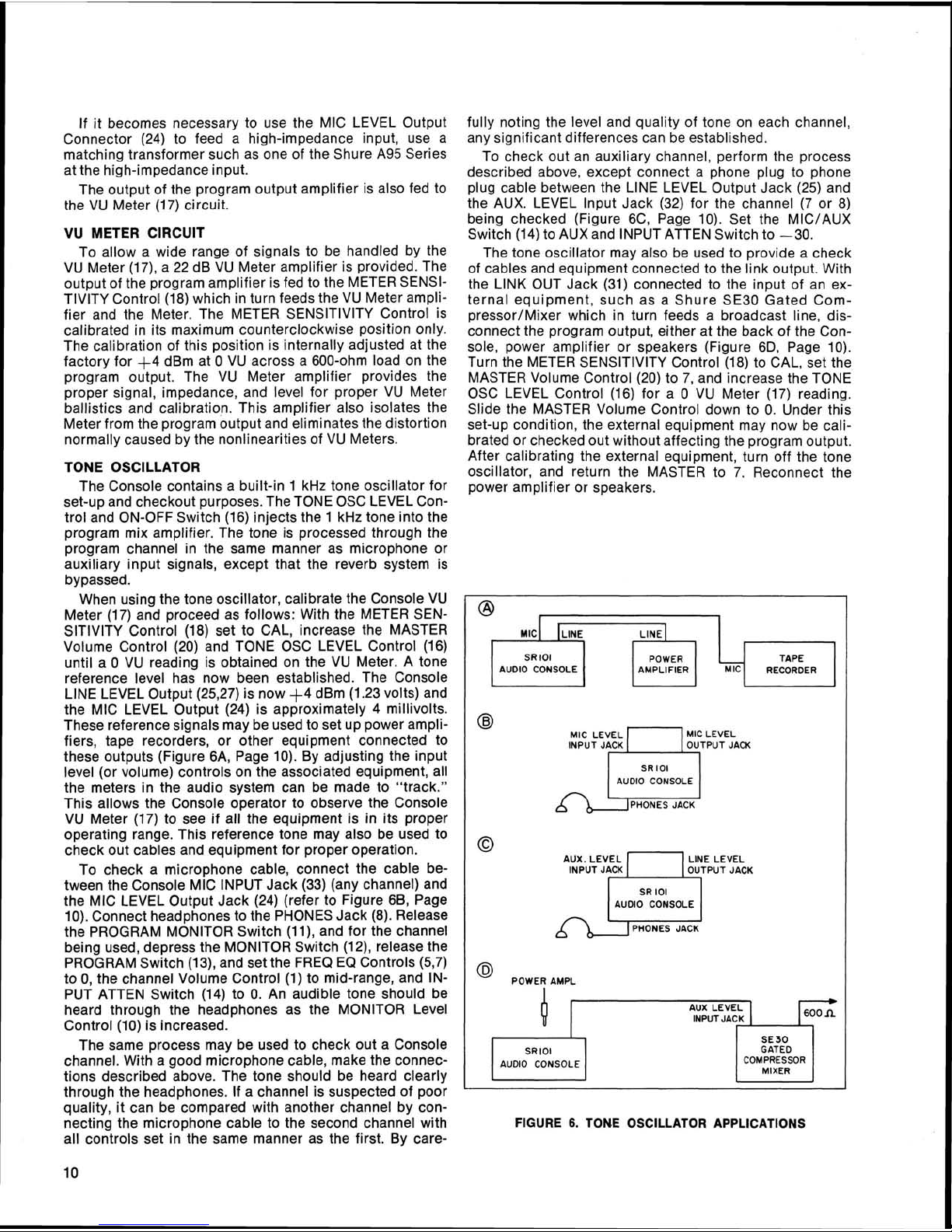
To check a microphone cable, connect the cable between the Console MIC INPUT Jack (33) (any channel) and
the MIC LEVEL Output Jack (24) (refer to Figure
6B, Page
10). Connect headphones to the PHONES Jack (8). Release
the PROGRAM MONITOR Switch
(ll), and for the channel
being used, depress the MONITOR Switch
(12), release the
PROGRAM Switch
(13), and set the FREQ EQ Controls (5,7)
to 0, the channel Volume Control (1) to mid-range, and INPUT
ATTEN Switch (14) to 0. An audible tone should be
heard through the headphones as the MONITOR Level
Control (10) is increased.
The same process may be used to check out a Console
channel. With
a
good microphone cable, make the connections described above. The tone should be heard clearly
through the headphones. If a channel is suspected of poor
quality, it can be compared with another channel by con-
necting the microphone cable to the second channel with
all controls set in the same manner as the first. By care-
fully noting the level and quality of tone on each channel,
any significant differences can be established.
To check out an auxiliary channel, perform the process
described above, except connect a phone plug to phone
plug cable between the LlNE LEVEL Output Jack (25) and
the AUX. LEVEL Input Jack (32) for the channel
(7
or 8)
being checked (Figure
6C, Page 10). Set the MIC/AUX
Switch (14) to AUX and INPUT ATTEN Switch to -30.
The tone oscillator may also be used to provide a check
of cables and equipment connected to the link output. With
the
LINK OUT Jack (31) connected to the input of an ex-
ternal equipment, such as a Shure SE30 Gated
Com-
pressor1Mixer
which in turn feeds a broadcast line, disconnect the program output, either at the back of the Console, power amplifier or speakers (Figure
6D, Page 10).
Turn the METER SENSITIVITY Control (18) to CAL, set the
MASTER Volume Control (20) to 7, and increase the TONE
OSC LEVEL Control (16) for a
0
VU
Meter (17) reading.
Slide the MASTER Volume Control down to
0. Under this
set-up condition, the external equipment may now be calibrated or checked out without affecting the program output.
After calibrating the external equipment, turn off the tone
oscillator, and return the MASTER to 7. Reconnect the
power amplifier or speakers.
,
MIC~
ILINE,
,
LINE^
,
,
SR I01 POWER TAPE
AUDIO CONSOLE AMPLIFIER RECORDER
@
MIC LEVEL
1)
MIC LEVEL
INPUT JACK OUTPUT JACK
SR
lOl
AUDIO CONSOLE
0
LlNE LEVEL
INPUT JACK
AUx.
LEVEL
n
OUTPUT JACK
SR
101
AUDIO CONSOLE
I
PHONES JACK
@
POWER AWL
AUX LEVEL
INPUT JACK
I
1
SR lOl
AUDIO CONSOLE
GATED
1
C0E;:SOR
1
I
MIXER
1
FIGURE
6.
TON'E OSCILLATOR APPLICATIONS
BASIC OPERATING HINTS
Should any difficulty be encountered in Console opera-
tion, the problem may often be traced to some simple
source
is offered as a basic guide to problems of this sort.
Symptom: Console is
Check: 1. Check that ac Dower source is "live" and
Symptom:
Check: 1. Check that PROGRAM Switch or Switches
such as an error in interconnection. The following
out)
that Console is plugged in.
2.
Check that POWER ON-OFF Switch (19) is
on.
3. Check to see that rear-panel
SLO-BLO Fuse (22) is good. 2. Check that channel PROGRAM Switch (13)
Console is "dead" (no output, VU Meter lamps
lit) 3. Check that AUX-MIC Switch (14) (channels
(13) are depressed.
"dead" (no output, VU Meter lamps
3AG-3116A Check: 1. Check for defective input cable or source.
Symptom:
2. Check that cable from PROGRAM
PUT/LINE
accidentally been connected to PROGRAM
OUTPUT/MIC LEVEL Connector (24).
3. Check that PHASE Switch (26) is not between positions.
4. Check that external equipment is properly
connected to
One channel is "dead" (other channels
ating properly)
is depressed.
7
and 8 only) is not between positions or in
the wrong position.
LEVEL Connector (27) has not
LINK Jacks (28,31).
OUT-
oper-
SR101 Series 2 Audio Console
SPECIAL OPERATING INSTRUCTIONS
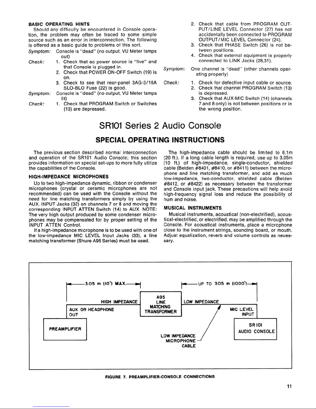
The previous section described normal interconnection The high-impedance cable should be limited to 6.lm
and operation of the SR101 Audio Console; this section (20 ft.). If a long cable length is required, use up to 3.05m
provides information on special set-ups to more fully utilize (10 ft.) of high-impedance, single-conductor, shielded
the capabilities of the Console.
HIGH-IMPEDANCE MICROPHONES
UP to two high-impedance dynamic, ribbon or condenser
microphones (crystal or ceramic microphones are not
recommended) can be used with the
need for line matching transformers simply by using the
AUX. INPUT Jacks (32) on channels
corres~ondincl INPUT ATTEN Switch (14) to AUX. NOTE:
very highoutput produced by s0m.e dondenser micro-
The
phones may be compensated for by proper setting of the
INPUT
the low-impedance MIC LEVEL Input Jacks
matching transformer (Shure A95 Series) must be used.
ATTEN Control.
If a high-impedance microphone is to be used with one of
Console without the
7
or 8 and moving the
(33), a line
cable (Belden
phone and line matching transformer, and add as much
low-impedance, two-conductor, shielded cable
#8412,'
and Console input jack. These precautions will help avoid
high-frequency
hum and noise.
Musical instruments, acoustical
tical-electrified, or electrified, may be amplified through the
Console. For acoustical instruments, place a microphone
close to the instrument strings, sounding board, or mouth.
Adjust equalization, reverb and volume controls as
sary.
#8401, #8410, or #8411) between the micro-
(Belden
or #8422) as necessary between the transformer
signal loss and reduce the possibility of
INSTRUMENTS
(non-electrified), acous-
neces-
3.05
m
(10') MAX.
r
AUX OR HEADPHONE
OUT
PREAMPLIFIER
-
FIGURE
-I
r
A95
LINE
MATCHING
TRANSFORMER
LOW IMPEDANCE
7.
PREAMPLIFIER-CONSOLE CONNECTIONS
PUP
LOW IMPEDANCE HIGH IMPEDANCE
MICROPHONE
CABLE
TO
305 m (1000')
1
MIC LEVEL
INPUT
SR
AUDIO CONSOLE
lOl
11
 Loading...