

Shure SR10 Operation And Service Manual
SR105
Power
Amplifier
OPERATION AND
SERVICE
MANUAL
Manufactured by
SHURE BROTHERS
INC.
222
Hartrey Avenue
Evanston, Illinois
60204
U.S.A.
WARNING
To reduce the risk of fire or electric shock, do not
expose this appliance to rain or extreme moisture.
Copyright
1979,
Shure Brothers Inc.
27A888
(SJ)
(95B652)
Printed in U.S.A.
SR105
Power Amplifier
SPECIFICATIONS
The following specifications apply to both SR105A and SR105B Power Amplifiers except where noted. The SR105A Power
Amplifier provides both direct-coupled speaker output and transformer-coupled, constant-voltage, 70-volt output. The
SRlO5B Power Amplifier is equipped for direct-coupled speaker output only.
.......
Amplifier Type All silicon transistor power
amplifier
Power Output
.......
.200 watts rms continuous to
4-ohm load
100 watts rms continuous to
8-ohm load
150 watts rms continuous to
70-volt line (33-ohm load)*
Voltage Gain
.........
27 22 dB (4-ohm load at 1 kHz)
35
e3.5 dB (33-ohm load at 1 kHz
across 70-volt output)'
Sensitivity
...........
1.2 volts nominal (full rated output)
Frequency Response
.
.
&I
.5 dB, 20-20,000 Hz (typical)
*2 dB, 50-15,000 Hz (typical,
70-volt output)"
Input Impedance
....
.39 kilohms &30%, balanced or
unbalanced*
25 kilohms
&30%, balanced or
unbalanced*
*
Total Harmonic
Distortion
........
.2% max. at 1 kHz, 200W (4-ohm
load, 28.3 Vrms output)
3% max. at 1 kHz,
150W (33-ohm
load, 70.7 Vrms output)*
Hum and Noise
......
.80 dB below rated output (less than
2.8
mV at direct-coupled speaker
output with Volume Control at
0)
Output Clipping Level. . 28.3 Vrms min. at 1 kHz (4-ohm
load)
Load lmpedance:
Direct-Coupled
Speaker Output
.
.4 ohms or greater (4 ohms min.)
70-Volt Output*
...
.I50 watts max. (33 ohms min.)
Load Regulation:
Di rect-Coupled
Speaker Output
. .
Less than 1 dB from no-load to 4-
ohm load at 200 watts rms output
....
70-Volt Output*
Less than 2 dB from no-load to
33-
ohm load at 150 watts rms output
Phasing..
...........
Pin 3 and phone jack tips of in-
puts in phase with speaker output phone jack tips, and 28V
and 70V terminals
Power Supply
........
120 volts, 50/60 Hz ac only. Power
consumption: 40 watts max. (20
watts typical) with no signal, 450
watts with
1
kHz signal and 200
watts output; 500 watts maximum
Temperature Range:
Operating
.........
-7' to 43OC (20' to 1 10°F)
Storage
...........
-34' to 74OC (-30' to 165OF)
Dimensions
.........
.I78 mm x 483 mm x 270 mm
(7 in. H x 19 in.
W
x 10% in.
D)
Weight:
SR105A
...........
15.66 kg (34 Ib 8 oz)
SR105B
...........
12.23 kg (27 Ib)
Finish
..............
Matte black
Installation
..........
Equipped for standard 19" (483
mm) rack mounting; may be operated in optional
A105A Carry-
ing Case
Certifications
........
Listed by Underwriters' Labora-
tories, Inc.; listed by Canadian
Standards Association as certified
Model
SR105A
only.
"Model
SR105B
only.
SR105
Power Amplifier
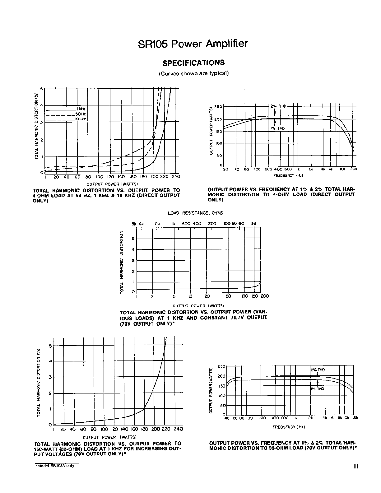
SPECIFICATIONS
(Curves
shown
are
typical)
FREQUENCY
(Hz1
OUTPUT POWER (WATTS)
TOTAL HARMONIC DISTORTION VS. OUTPUT POWER TO
4-OHM LOAD AT 50 HZ, 1 KHZ
&
10 KHz (DIRECT OUTPUT
ONLY)
OUTPUT POWER VS. FREQUENCY AT 1%
81
2%
TOTAL HARMONIC DISTORTION TO 4-OHM LOAD (DIRECT OUTPUT
ONLY)
LOAD RESISTANCE, OHMS
OUTPUT POWER (WATTS)
TOTAL HARMONIC DISTORTION VS. OUTPUT POWER (VARIOUS LOADS) AT
1
KHz AND CONSTANT 70.7V OUTPUT
(70V OUTPUT ONLY)*
FREQUENCY ( H
J
OUTPUT POWER (WATTS)
TOTAL HARMONIC DISTORTION VS. OUTPUT POWER TO
OUTPUT POWER VS. FREQUENCY AT 1%
&
2%
TOTAL HAR-
150-WATT (33-OHM) LOAD AT 1 KHz FOR INCREASING OUT-
MONlC DISTORTION TO 33-OHM LOAD (70V OUTPUT ONLY)*
PUT VOLTAGES (70V OUTPUT ONLY)*
'Model
SRIO~A
only.
iii

SR105
Power Amplifier
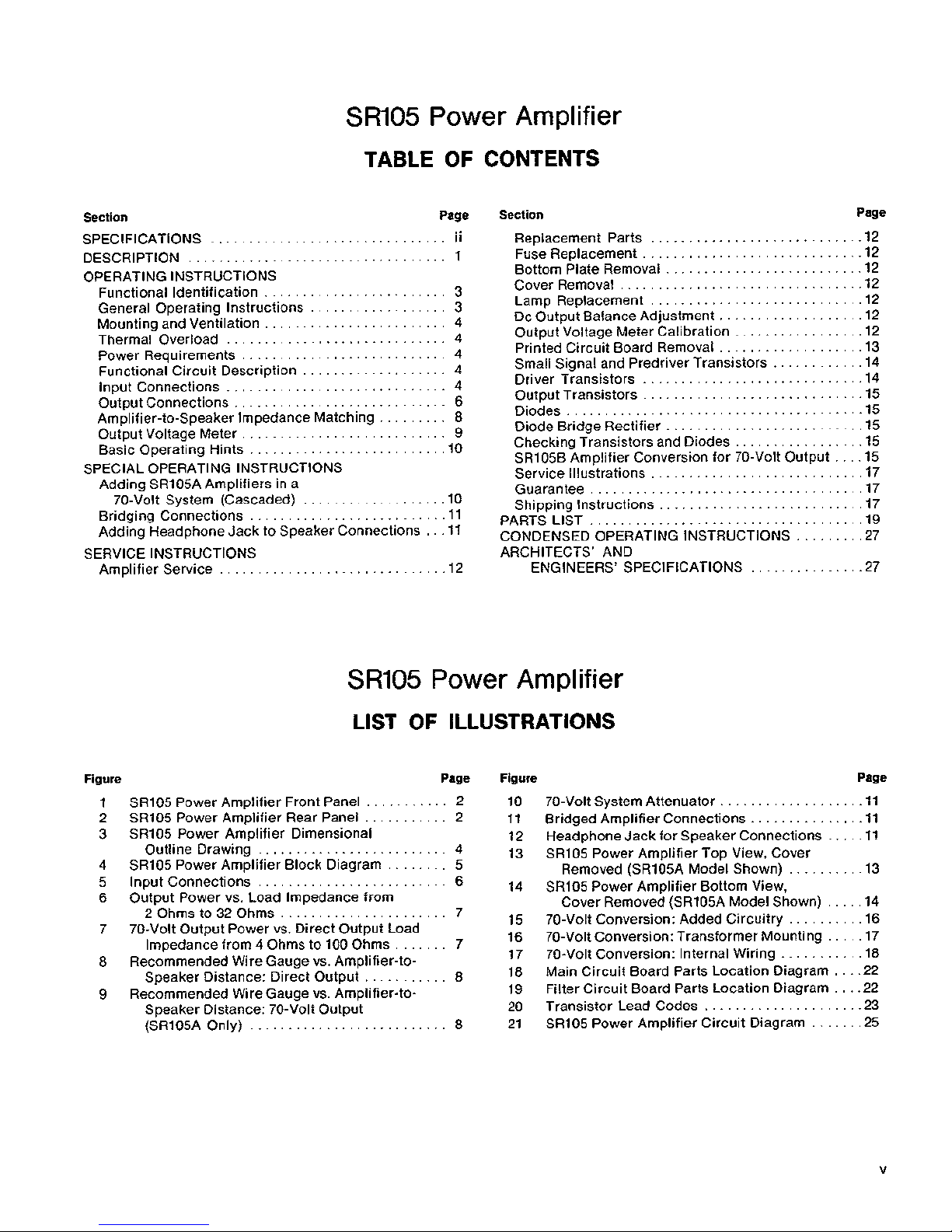
TABLE OF CONTENTS
Section Page
...............................
SPECIFICATIONS ii
DESCRIPTION
..................................
1
OPERATING INSTRUCTIONS
........................
Functional Identification 3
..................
General Operating Instructions
3
........................
Mounting and Ventilation 4
Thermal Overload
.............................
4
...........................
Power Requirements 4
...................
Functional Circuit Description 4
Input Connections
.............................
4
............................
Output Connections 6
Amplifier-to-Speaker Impedance Matching
.........
8
Output Voltage Meter
...........................
9
..........................
Basic Operating Hints 10
SPECIAL OPERATING INSTRUCTIONS
Adding
SRlO5A Amplifiers in a
...................
70-Volt System (Cascaded) 10
..........................
Bridging Connections 11
Adding Headphone Jack to Speaker Connections
...
11
SERVICE INSTRUCTIONS
..............................
Amplifier Service 12
Section Page
............................
Replacement Parts 12
.............................
Fuse Replacement 12
..........................
Bottom Plate Removal 12
................................
Cover Removal 12
............................
Lamp Replacement 12
...................
Dc Output Balance Adjustment 12
Output Voltage Meter Calibration
.................
12
...................
Printed Circuit Board Removal 13
Small Signal and Predriver Transistors
............
14
.............................
Driver Transistors 14
.............................
Output Transistors 15
Diodes
.......................................
15
..........................
Diode Bridge Rectifier 15
Checking Transistors and Diodes
.................
15
SR105B Amplifier Conversion for 70-Volt Output
....
15
Service lllustrations
............................
17
Guarantee
....................................
17
Shipping Instructions
...........................
17
....................................
PARTS LIST 19
CONDENSED OPERATING INSTRUCTIONS
.........
27
ARCHITECTS' AND
ENGINEERS' SPECIFICATIONS
...............
27
SR105
Power Amplifier
LlST OF ILLUSTRATIONS
Figure Page
...........
1 SR105 Power Amplifier Front Panel 2
2 SR105 Power Amplifier Rear Panel
...........
2
3
SR105 Power Amplifier Dimensional
.........................
Outline Drawing 4
4
SR105 Power Amplifier Block Diagram
........
5
5 Input Connections
.........................
6
6
Output Power vs
.
Load lmpedance from
2 Ohms to 32 Ohms
......................
7
7
70-Volt Output Power vs
.
Direct Output Load
Impedance from 4 Ohms to 100 Ohms
.......
7
8
Recommended Wire Gauge vs . Amplifier-to-
Speaker Distance: Direct Output
...........
8
9
Recommended Wire Gauge vs . Amplifier-to-
Speaker Distance: 70-Volt Output
(SR105A Only)
..........................
8
Figure Page
10 70-Volt System Attenuator
...................
11
11
Bridged Amplifier Connections
...............
11
12 Headphone Jack for Speaker Connections
.....
11
13
SR105 Power Amplifier Top View, Cover
Removed
(SR105A Model Shown)
..........
13
14
SR105 Power Amplifier Bottom View.
Cover Removed
(SR105A Model Shown)
.....
14
15
70-Volt Conversion: Added Circuitry
..........
16
.....
16 70-Volt Conversion: Transformer Mounting 17
...........
17 70-Volt Conversion: Internal Wiring 18
....
18 Main Circuit Board Parts Location Diagram 22
....
19 Filter Circuit Board Parts Location Diagram 22
.....................
20 Transistor Lead Codes 23
.......
21 SR105 Power Amplifier Circuit Diagram 25

SR105
Power
Amplifier
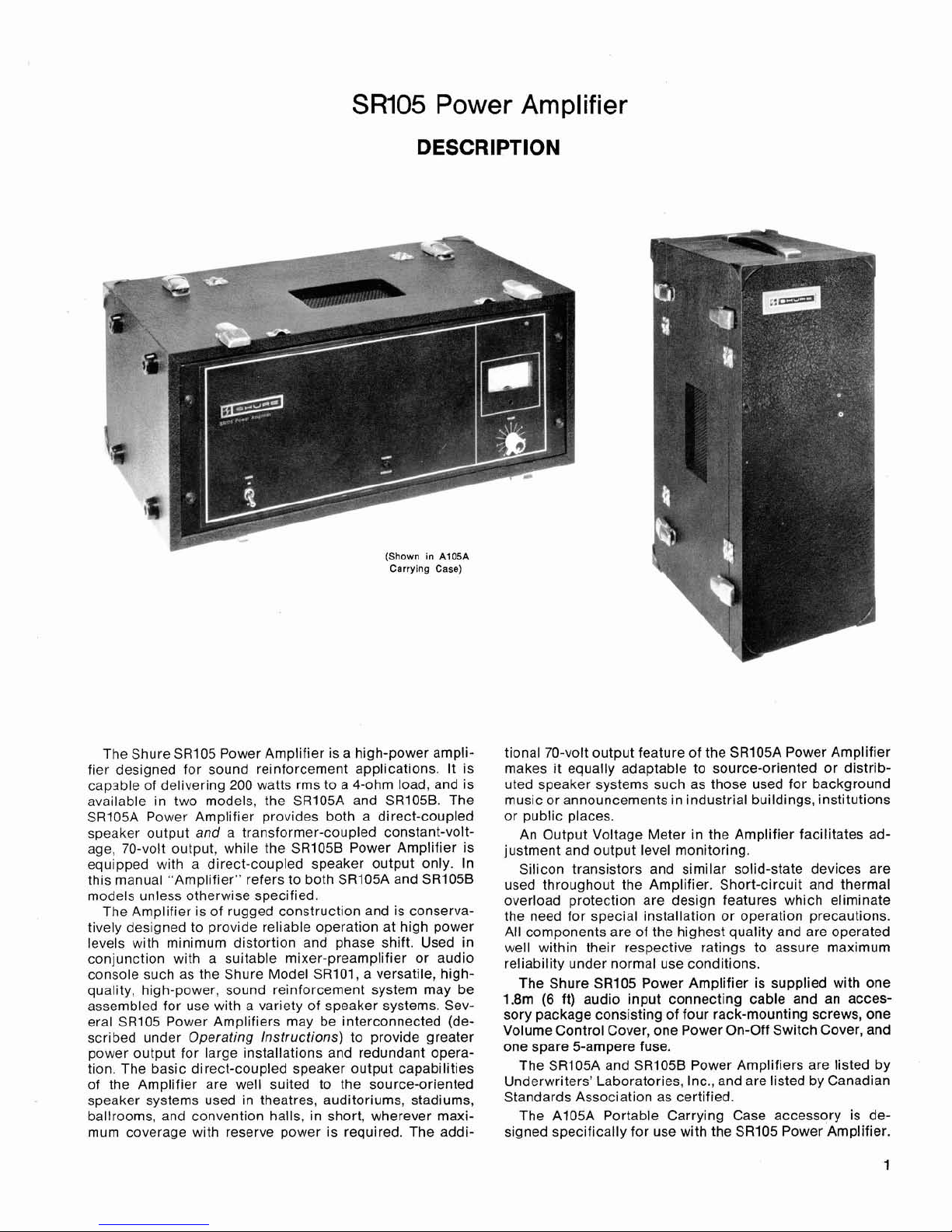
DESCRIPTION
(Shown
in
A105A
Carrying
Case)
The Shure SR105 Power Amplifier is a high-power amplifier designed for sound reinforcement applications. It is
capsble of delivering 200 watts rms to a 4-ohm load, and is
available in two models, the SR105A and SR105B. The
SRlO5A Power Amplifier provides both a direct-coupled
speaker output and a transformer-coupled constant-voltage, 70-volt output, while the
SR105B Power Amplifier is
equipped with a direct-coupled speaker output only. In
this manual "Amplifier" refers to both
SRI05A and SRlOSB
models unless otherwise specified.
The Amplifier is of rugged construction and is conservatively designed to provide reliable operation at high power
levels with minimum distortion and phase shift. Used in
conjunction with a suitable mixer-preamplifier or audio
console such as the Shure Model
SR101, a versatile, highquality, high-power, sound reinforcement system may be
assembled for use with a variety of speaker systems. Several
SR105 Power Amplifiers may be interconnected (de-
scribed under Operating Instructions) to provide greater
power output for large installations and redundant operation. The basic direct-coupled speaker output capabilities
of the Amplifier are well suited to the source-oriented
speaker systems used in theatres, auditoriums, stadiums,
ballrooms, and convention halls, in short, wherever maximum coverage with reserve power is required. The addi-
tional 70-volt output feature of the
SR105A Power Amplifier
makes it equally adaptable to source-oriented or distributed speaker systems such as those used for background
music or announcements in industrial buildings, institutions
or public places.
An Output Voltage Meter in the Amplifier facilitates ad-
justment and output level monitoring.
Silicon transistors and similar solid-state devices are
used throughout the Amplifier. Short-circuit and thermal
overload protection are design features which eliminate
the need for special installation or operation precautions.
All components are of the highest quality and are operated
well within their respective ratings to assure maximum
reliability under normal use conditions.
The Shure
SR105 Power Amplifier is supplied with one
1.8m
(6
ft) audio input connecting cable and an accessory package consisting of four rack-mounting screws, one
Volume Control Cover, one Power On-Off Switch Cover, and
one spare 5-ampere fuse.
The
SR105A and SRIO5B Power Amplifiers are listed by
Underwriters' Laboratories, Inc., and are listed by Canadian
Standards Association as certified.
The
A105A Portable Carrying Case accessory is de-
signed specifically for use with the
SR105 Power Amplifier.
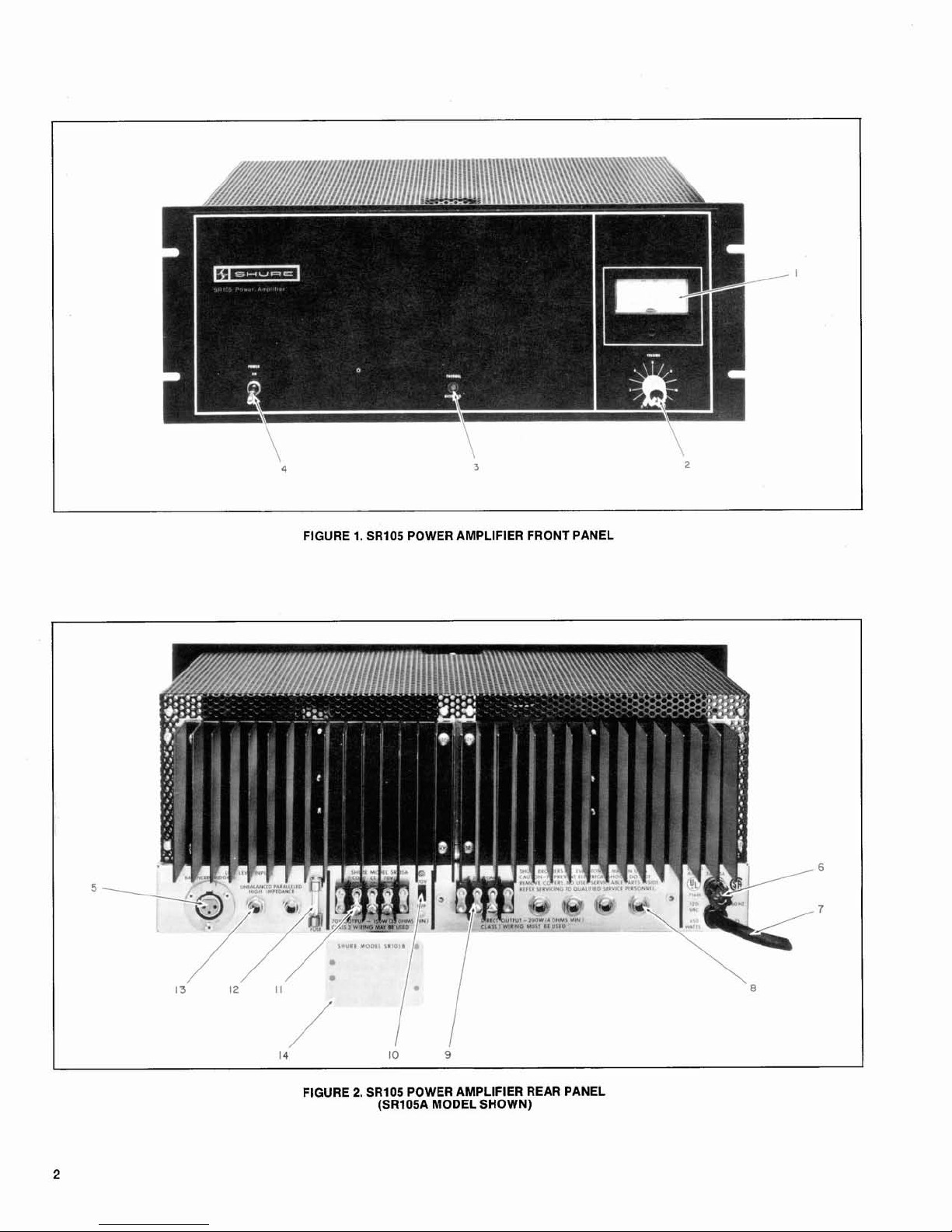
FIGURE 1. SR105 POWER AMPLIFIER FRONT PANEL
FIGURE
2.
SR105 POWER AMPLIFIER REAR PANEL
(SR105A MODEL SHOWN)
SR105
Power Amplifier
OPERATING INSTRUCTIONS
FUNCTIONAL IDENTIFICATION (Refer to Figures 1 and 2,
Page 2).
1. OUTPUT VOLTAGE Meter
-
lndicates Amplifier out-
put voltage in percentage of maximum voltage.
2. VOLUME
Control - Controls Amplifier output level.
3. THERMAL OVERLOAD Indicator Lamp
-
lndicates
Amplifier shutdown due to excessive heat sink temperature.
4. POWER ON-OFF Switch
-
Applies ac power to Ampli-
fier.
5. BALANCED BRIDGING
lnput Jack - Provides for bal-
anced bridging, high-impedance input connection.
6.
3AGl5A Ac Line Fuse - Protects Amplifier ac input
line aaainst overload.
-
7. Ac Line Cord
-
Connects ac power to Amplifier power
supply.
8. DIRECT OUTPUT Jacks (Four) - Provide for output
connection to
direct-coupled speaker systems.
9. DIRECT OUTPUT
Terminal Strip - Provides for output
connection to
direct-coupled speaker systems.
10. 70V-OFF Switch
(SRIO5A Amplifier only) - Activates
70-volt output transformer for use with distributed
speaker systems.
11. 70V OUTPUT Terminal Strip
(SRI05A Amplifier only)
-
Provides for output connection to 70-volt distributed
speaker systems.
12. SPARE FUSE
Fuseholder- Holds spare 3AG-5A
power
supply fuse.
13. UNBALANCED PARALLELED
HlGH IMPEDANCE In-
put Jacks (Two) - Provide unbalanced (one side
grounded) input connections for use with
high-im-
pedance sources.
14.
70-Volt Output Cover Plate (SRIOSB Amplifier only)
-
Covers pre-drilled and marked area where Switch (10)
and Terminal Strip (11) are located.
GENERAL OPERATING INSTRUCTIONS
WARNING
Voltages in this equipment are hazardous to life. Make
all input and output connections with ac power disconnected. Refer servicing to
qualified service per-
sonnel.
DIRECT SPEAKER OUTPUT OPERATION
(MODEL
SRIO5A and SR105B AMPLIFIERS)
1. Install Amplifier before making electrical connections.
Using hardware supplied, secure
Amplifier in rack or
carrying case, allowing at least 51 mm
(2
in.) above
and behind case for ventilation. Use forced-air cooling
for multiple-amplifier installations.
2. Set Switches
(4,lO) to OFF and VOLUME Control (2)
to
0.
3. Connect required speakers to Amplifier DIRECT OUTPUT jacks (8)
andlor to terminal strip (9), using proper
wire size and arranging speaker connections for
total
speaker load impedance as close to 4 ohms as possible.
Remove DIRECT OUTPUT Cover (14) and use rightangle phone plugs to connect speakers to Amplifier.
When using DIRECT OUTPUT Terminal Strip (9), thread
wires through Cover grommet. Replace cover.
CAUTION
In multiple speaker installations, be sure not to ex-
ceed maximum power rating of any speaker.
4. Connect audio
console or microphone mixer output to
Amplifier
UNBALANCED PARALLELED HlGH IMPE-
DANCE
lnput Jack (13) (standard phone jack). For in-
terconnections up to 15m (50 ft), use
single-conductor, shielded, low-capacitance cable. For interconnections longer than 50 ft, use 600-ohm balanced line
into Amplifier BALANCED BRIDGING lnput Jack (5)
(professional, 3-pin, female audio connector).
5.
Connect additional power amplifiers or other auxiliary
equipment as required to remaining Amplifier input
jacks.
6. Connect
line cord (7) to grounded 120 Vac &lo%,
50/60
Hz source capable of supplying 450 watts.
7.
With VOLUME Control (2) set at 0, turn front-panel
POWER Switch (4) on. Adjust VOLUME Control to de-
sired
amplifier operating level.
CONSTANT-VOLTAGE 70-VOLT SPEAKER OUTPUT
(MODEL
SR105A AMPLIFIER ONLY)
1. Connect
auxiliary equipment as for direct speaker op-
eration in steps 1, 2, 4, 5 and 6 above.
2. Connect required speakers to 70V OUTPUT Terminals
(11) and, if necessary, DIRECT OUTPUT Connectors
(8,9). Total speaker impedance should be as close to 33
ohms as possible. Be
careful not to exceed Amplifier
150-watt power output capability. (See Output Con-
nections, Page 6.)
3. Connect audio
console or microphone mixer output to
Amplifier UNBALANCED PARALLELED HlGH IMPEDANCE Input Jack (13) (standard phone jack). For interconnections up to 15m (50 ft), use
single-conductor, shielded, low-capacitance cable. For interconnections longer than 50 ft, use 600-ohm balanced line
into Amplifier BALANCED BRIDGING lnput Jack (5)
(professional, 3-pin, female audio connector).
4. Turn 70V-OFF Switch (10) to 70V.
5.
Connect line cord (7) to grounded 120 Vac *lo%,
50160
Hz
source.
6.
With VOLUME Control
(2)
set at
0,
turn front-panel
POWER Switch (4) on. Adjust VOLUME Control to desired amplifier operating level.
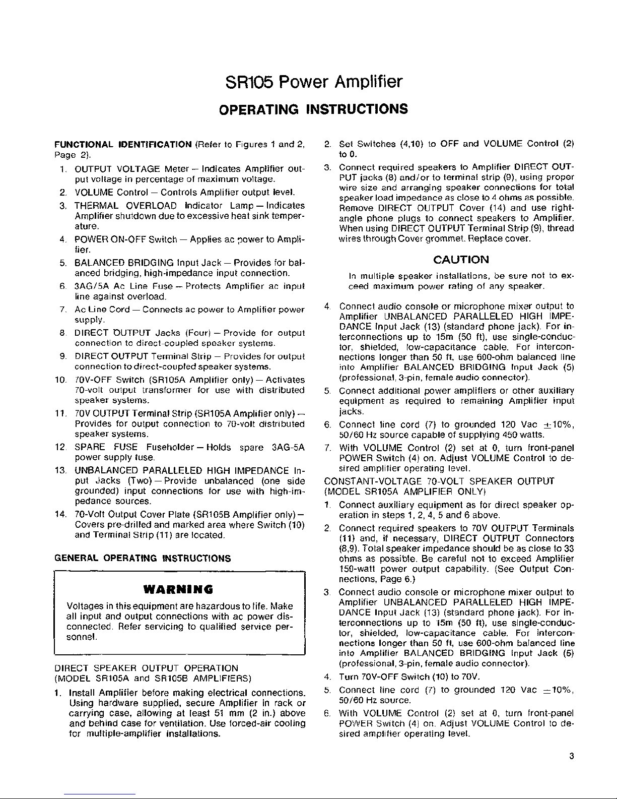
MOUNTING AND VENTILATION
The SR105 Power Amplifier is designed for rack-mounting in a standard 19-inch (483 mm) audio equipment cabinet
rack and is supplied with the necessary mounting hardware.
To insure adequate air circulation, a minimum clearance of
51 mm (2 in.) should be provided above and behind the
Amplifier (see Figures 3, Page 4). If the cabinet ambient
temperature reaches
43OC (llO°F), forced air ventilation
should be provided to avoid the possibility of thermal overload (see following section). The Amplifier may be operated
in an ambient temperature range from
-7"
to 43°C (20"
to 110°F) in continuous duty without derating.
The Amplifier may also be operated while mounted in a
Shure
A105A Carrying Case.
P,
.
.
270
mm'
?
-00-518 IN.)-
I
*
NOT INCLUDING CABLE AND LlNE CORD CLEARANCE DEPTH.
I
FIGURE
3.
SR105 POWER AMPLIFIER
DIMENSIONAL OUTLINE DRAWING
THERMAL OVERLOAD
The SR105 Power Amplifier is equipped with thermal
sensing switches on the output transistor heat sinks. The
thermal switches are set to sh~it off ac power to the Amplifier when a temperature of 90°C (194°F) is attained on the
heat sinks; the switches automatically recycle and re-apply
power when the
heat sink temperature drops to 73°C
(164°F). A THERMAL OVERLOAD light
(3),
located on the
front panel of the Amplifier, indicates if thermal cycling
has occurred. Thermal cycling may occur if air is not allowed to circulate across the black finned heat sinks and
through the grilles of the Amplifier, or if there is a pro-
longed short-circuit on the output.
POWER REQUIREMENTS
The SR105 Power Amplifier is furnished with a threeconductor power cable and three-prong grounded plug
(7). Connect the power cable to an outlet which supplies
120
~10% volts ac, 50160
Hz
power. The maximum power
consumption at 120 volts under any normal operating condition is 450 watts (3.75 amperes at 120 volts).
Idle power
consumption with no input signal is nominally 20 watts.
If extension cords are required to supply power to the
Amplifier, a high quality 18-gauge or larger cord should
be used.
A POWER toggle switch on the front panel
(4)
controls
the application of ac power to the Amplifier. The
tamper-
proof cover supplied may be used to eliminate accidental
movement of this switch.
Main ac power fusing is provided by a 5-ampere, type
3AG, cartridge-type fuse (6) located on the rear panel. A
spare ac power fuse is supplied for mounting in the clip on
the rear panel (12).
Additional protection is provided by wired-in fuses in the
main ac power circuit (FI, 8 amperes) and in the ac pilot
lamp circuit (F3, 1 ampere). These fuses are located under
the chassis.
FUNCTIONAL CIRCUIT DESCRIPTION
(See Figure 4,
Page 5)
The inputs of the
SR105 Power Amplifier consist of two
unbalanced (grounded) phone jacks (13) and one balancedbridging, three-pin, female audio connector (5). The balanced-bridging input is wired in parallel to the phone jacks
after passing through an isolation transformer. The input
signal then passes through the VOLUME Control
(2), and
if the Amplifier is an
SR105A, either passes through a Filter
Assembly and 70V-OFF Switch (10) to the Power Amplifier
circuitry, or bypasses the Filter Assembly and goes directly
to the Power Amplifier circuitry. In the
SR105B Amplifier the
signal passes directly from the VOLUME Control (2) to the
Power Amplifier circuitry.
The Power Amplifier circuitry contains a dc balance adjustment to minimize idle power consumption and eliminate
dc offset at the direct-coupled
(28V) output. The balance
adjustment is generally only performed when active Power
Amplifier circuit components are replaced.
The metering circuit, located at the output of the Power
Amplifier circuit, contains a meter calibration adjustment,
a meter rectifier, and an output meter that indicates percentage of output voltage. NOTE: 100% is the maximum
Amplifier output voltage prior to clipping regardless of load.
Maximum power output is obtained with a direct-coupled
speaker load impedance of 4 ohms, or a 70-volt output
speaker load of 150 watts (33 ohms), or a combination of
direct-coupled and 70-volt loads which results in optimum
loading for maximum power output.
The Power Amplifier circuit output goes to four phone
jacks (8) and one two-contact terminal strip (9). In the
SR105A Amplifier, the output goes through the 70V-OFF
Switch
(lo), a constant-voltage, 70-volt output transformer,
and a three-contact terminal strip (1 1).
A detailed description of the Amplifier circuits and controls and their uses is provided in the following paragraphs
of this section.
INPUT CONNECT IONS
Three LlNE LEVEL INPUTS Connectors are located on
the rear panel of the Amplifier (see Figure 2, Page 2). A
professional, three-pin, female audio connector
(5)*
pro-
vides a balanced bridging, high-impedance input connec-
tion. Unbalanced, high-impedance input connections are
provided by two standard
1/4"
phone jacks (13) wired in
parallel.
The Amplifier may be driven to full-rated output by any
audio console, preamplifier or microphone mixer capable
of delivering 1.2 volts across a 25-kilohm load.
When using the Shure
SR101 Audio Console as the
mixer-preamplifier, connect the cable supplied with the
Amplifier from one of the PROGRAM OUTPUTS Jacks
labeled LlNE LEVEL on the
SR101 to one of the LlNE LEVEL
INPUT Jacks (13) labeled UNBALANCED PARALLELED
HIGH IMPEDANCE on the Amplifier (see Figure 5A, Page
6). If a longer interconnecting cable is desired, a
single-
conductor, shielded, low-capacitance cable (such as Bel-
den #8401, 8410, or 8411) should be used.
'Des~gned to mate with Cannon
XL
Ser~es, Sw~tchcraft
A3
(0
G
)
Series, or
equivalent
connector
FIGURE
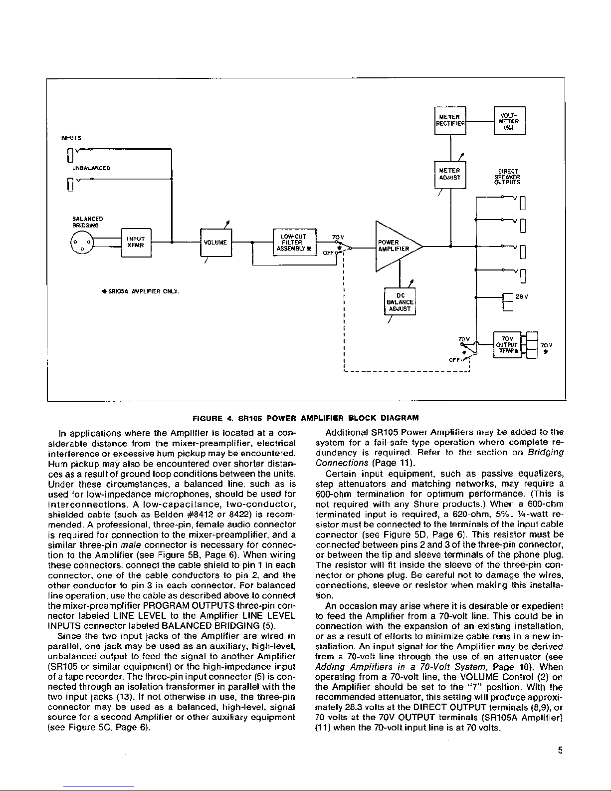
4.
SR105
POWER AMPLIFIER BLOCK DIAGRAM
METER
RECTIFIER
In applications where the Amplifier is located at a considerable distance from the mixer-preamplifier, electrical
interference or excessive hum pickup may be encountered.
Hum pickup may also be encountered over shorter distances as a result of ground loop conditions between the units.
Under these circumstances, a balanced line, such as is
used for low-impedance microphones, should be used for
interconnections. A low-capacitance, two-conductor,
shielded cable (such as
Belden #8412 or 8422) is recommended. A professional, three-pin, female audio connector
is required for
wnnection to the mixer-preamplifier, and a
similar three-pin male connector is necessary for connec-
tion to the Amplifier (see Figure 5B, Page 6). When wiring
these connectors, connect the cable shield to pin 1 in each
connector, one of the cable conductors to pin 2, and the
other conductor to pin 3 in each connector. For balanced
line operation, use the cable as described above to connect
the mixer-preamplifier PROGRAM OUTPUTS three-pin connector labeled
LlNE LEVEL to the Amplifier LlNE LEVEL
INPUTS connector labeled BALANCED BRIDGING (5).
Since the two input jacks of the Amplifier are wired in
parallel, one jack may be used as an auxiliary, high-level,
unbalanced output to feed the signal to another Amplifier
(SR105 or similar equipment) or the high-impedance input
of a tape recorder. The three-pin input connector (5) is con-
nected through an isolation transformer in parallel with the
two input jacks (13). If not otherwise in use, the three-pin
connector may be used as a balanced, high-level, signal
source for a second Amplifier or other auxiliary equipment
(see Figure
5C, Page 6).
VOLT-
METER
(70)
Additional SR105 Power Amplifiers may be added to the
system for a fail-safe type operation where complete re-
dundancy is required. Refer to the section on Bridging
Connections (Page 11).
Certain input equipment, such as passive equalizers,
step attenuators and matching networks, may require a
600-ohm termination for optimum performance. (This is
not required with any Shure products.) When a 600-ohm
terminated input is required, a 620-ohm,
5%, %-watt resistor must be connected to the terminals of the input cable
connector (see Figure 5D, Page 6). This resistor must be
connected between pins 2 and 3 of the three-pin connector,
or between the tip and sleeve terminals of the phone plug.
The resistor will fit inside the sleeve of the three-pin con-
nector or phone plug. Be careful not to damage the wires,
connections, sleeve or resistor when making this installation.
An occasion may arise where it is desirable or expedient
to feed the Amplifier from a 70-volt line. This could be in
connection with the expansion of an existing installation,
or as a result of efforts to minimize cable runs in a new installation. An input signal for the Amplifier may be derived
from a 70-volt line through the use of an attenuator (see
Adding Amplifiers in
a
70-Volt System, Page 10). When
operating from a 70-volt line, the VOLUME Control (2) on
the Amplifier should be set to the "7" position. With the
recommended attenuator, this setting will produce approximately 28.3 volts at the DIRECT OUTPUT terminals
(8,9),
or
70 volts at the 70V OUTPUT terminals
(SRlO5A Amplifier)
(1 1) when the 70-volt input line is at 70 volts.
INPUTS
0''
-
I'
UNBALANCED
a
BALANCED
BRIDGING
INPUT
DIRECT
SPEAKER
OUTPUTS
I
I
-
METER
ADJUST
FILTER
d
=
'0
11
/
?
XFMR
VOLUME
ASSEMBLY
!&
LOW-CUT 70
V
/
I
I
I
I
I
f
!&
SRIOSA AMPLIFIER ONLY. I
I
I
BALANCE
I
I
I
1
1
I
I
I
I
I
XFMR*
*
I
I
I
L
- - - - - - - - - - - - - -
-
- -
-
-
-1
 Loading...