

Page 1
MODEL SM94
UNIDIRECTIONAL CONDENSER MICROPHONE
The Model SM94 is a unidirectional electret condenser
microphone tailored to the instrument miking needs of professional
musicians and sound engineers in both live performance and
sound recording. Its smooth, flat frequency response is free of
either a “presence peak” or a low-frequency rolloff, making it a
perfect choice for all types of musical instruments. The SM94 is
equally at home in sound reinforcement systems or in sound
studios and motion picture/TV scoring stages. When used with the
optional windscreen, the SM94 can be used by vocalists and
speechmakers who desire a wide, flat response with minimum
coloration.
The SM94 can be powered by any phantom power source, or by
an internal 1.5-volt AA battery. The battery, which serves as a
backup power source in the event of phantom power failure, can
provide up to 5,000 hours of continuous operation.
The SM94 is supplied with a swivel adapter for use on a
microphone stand, boom or gooseneck, and a zippered vinyl
storage bag. Model SM94-LC is supplied without a cable.
Accessories include a foam windscreen (A3WS), two-channel
phantom power supply (PS1A), and 7.6 m (25 ft.) microphone
cable (C25J).
Model SM94 User Guide
• Accepts 12 to 48 Vdc phantom power
• Rugged all–metal construction
• Usable over wide range of environmental conditions
• Built–in battery power backup
• Optional foam windscreen
SPECIFICATIONS
Type
Cardioid condenser (electret bias)
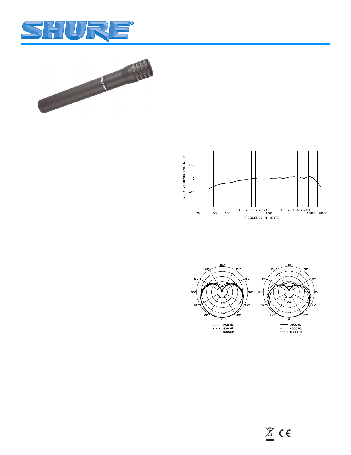
Frequency Response
40 to 16,000 Hz (see Figure 1)
TYPICAL FREQUENCY RESPONSE
FIGURE 1
Polar Pattern
Cardioid (unidirectional)–uniform with frequency,
symmetrical about axis (see Figure 2)
Features
• Wide, flat response for optimum musical instrument sound reproduction
• Full spectrum sound–no presence peak or low-end rolloff
• Cardioid polar pattern that is uniform with frequency and symmetrical about axis for maximum rejection of unwanted sound
and minimum of-axis coloration
• Very low susceptibility to RF and electromagnetic hum
• Low distortion output and wide dynamic range for variety of load
impedances
• Shock–mounted cartridge for reduced handling noise
©2005, Shure Incorporated
27C2689 (Rev. 5)
TYPICAL POLAR PATTERNS
FIGURE 2
Printed in U.S.A.
Page 2
Output Impedance
Rated at 150 Ω; 200 Ω actual
Recommended Minimum Load Impedance
800 Ω
Sensitivity (at 1,000 Hz)
Open Circuit Voltage: –49 dBV/Pa (3.5 mV) (phantom)
–50 dBV/Pa (3.2 mV) (battery) (1 Pa = 94dB SPL)
Output Clipping Level (1 kHz, 3% THD)
800-Ω Load–14 dBV (0.63 V) (phantom), 1% THD;
–23 dBV (0.71 V) (battery), 3% THD
Total Harmonic Distortion
< 0.25% (130 dB SPL at 250 Hz into 800 Ω load)
Maximum SPL
800 Ω Load: 141 dB (phantom), 123 dB (battery)
Hum Pickup
–3 dB equivalent SPL in a 1 millioersted field (60 Hz)
Output Noise (equivalent sound pressure levels;
measured with true rms voltmeter)
22 dB typical, A-weighted
25 dB typical, weighted per DIN 45 505
Dynamic Range
119 dB (phantom); 101 dB (battery) (maximum SPL,
2000–Ω load, to A–weighted noise level)
Signal-to-Noise Ratio
72 dB (IEC 651)* at 94 dB SPL
Overvoltage Protection
Maximum External Voltage Applied to Pins 2 and 3
with respect to Pin 1: +52Vdc
Reverse polarity protected to 75 Vdc
Polarity
Positive pressure on diaphragm produces positive
voltage on pin 2 relative to pin 3
Cartridge Capacitance
24 pF
Power
Phantom Operation
Supply Voltage: 11 to 52 Vdc, (+) pins 2 and 3
Current Drain: 1.0 to 1.2 mA max. at 52 Vdc
Battery Operation
Type: 1.5 V alkaline, AA size (NEDA 15A)
Life: Up to 5,000 hours with fresh battery
Environmental Conditions
Temperature:
Storage: . . . . . . . –29° to 74° C (–20° to 165° F)
Operating: –6.7° to 49° C (20° to 120° F)
Humidity:
Storage . . . . 0–95% relative humidity at room
temperature (72° to 80° F, 22° to 27° C)
Connector
XLR professional audio 3-Pin
Case
Steel and brass construction with gray finish and
stainless steel mesh grille
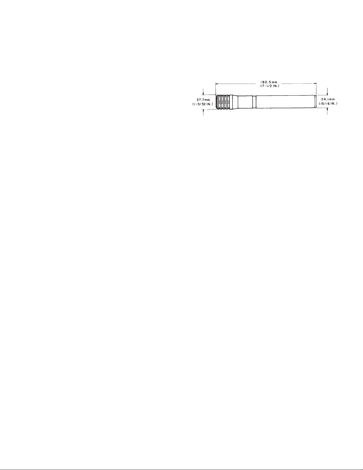
Dimensions
See Figure 3
OVERALL DIMENSIONS
FIGURE 3
Weight
Net 250 grams (8.8 oz) less battery
Packaged SM94-LC: 949.7 grams (2 Ib 1 1/2 oz)
Certification
Eligible to bear CE Marking. Conforms to European EMC Directive
89/336/EEC. Meets applicable tests and performance criteria in
European Standard EN55103 (1996) parts 1 and 2, for residential
(E1) and light industrial (E2) environments.
*S/N ratio is difference between microphone output at 94 dB SPL and
microphone self-noise A-weighted.
OPERATION
The SM94 is designed for phantom powering by a Shure PS1A
Power Supply, or by any microphone power supply providing 12 to
48 Vdc phantom voltage, or by any microphone mixer (such as the
Shure SCM262 and SCM268) with a phantom supply. In addition,
the SM94 can be powered by a single 1.5-volt AA alkaline battery.
The battery also serves as a backup in case of phantom power
failure. A new alkaline battery will provide up to 5,000 hours of
continuous microphone operation. Note that the microphone is
powered at all times during battery operation but there is no battery
drain during phantom-powered operation.
BATTERY OPERATION
Disconnect the microphone cable, and unscrew the SM94 handle,
turning counterclockwise (from top) until the handle is free of the
microphone body. Slide the handle away from the grille, exposing
the battery compartment. Insert a new battery (or replace the old
battery), observing the polarity marking in the compartment.
Slide the handle toward the grille, and tighten the handle by turning
it clockwise (from top).
WIND NOISE
Use the optional foam windscreen (A3WS) when using the SM94
outdoors on a windy day, indoors near strong air currents such as
air-moving equipment, or as a vocal microphone.
CIRCUIT DESCRIPTION
A block diagram of the SM94 is shown in Figure 4. The capacitor
cartridge is followed by an impedance converter stage. This stage
has an active load to obtain good load-driving capability with the
low battery voltage of 1.5 volts.
The audio signal is transformer-coupled for a balanced output to
the microphone connector. An active power supply circuit
2
Page 3
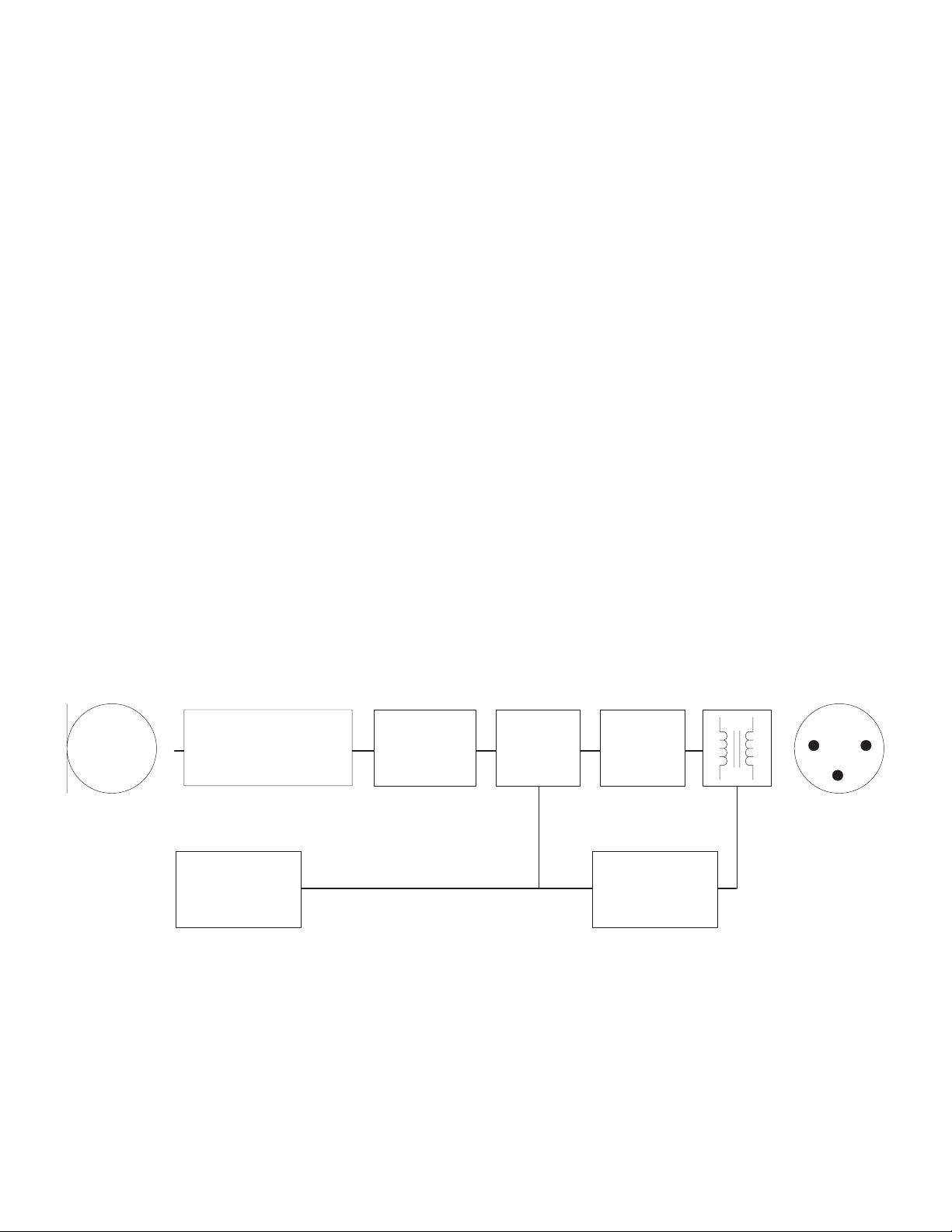
regulates the phantom voltage, and the 1.5-volt battery provides
instantaneous backup in case the phantom power supply fails. The
regulator/reverse voltage protector provides built-in protection
against miswired cables and equipment.
TROUBLESHOOTING
Due to the circuit complexity of the SM94, only basic servicing is
recommended. The following steps should be taken if problems
arise:
1. Check the power supply output voltage. For the Shure PS1A,
this should be 21.5, ±1.5 Vdc, open circuit.
2. Check the voltage on connector pins 2 and 3 (at back of
connector, with cable connector removed from shell, but
connected to microphone). The voltage at pins 2 and 3 with
reference to pin 1 should be between 10 and 48 Vdc.
3. If the microphone does not work on phantom power, battery
operation may still be possible. Similarly, if battery operation is
impaired, the SM94 may still operate on phantom power. In
either case, you should send the microphone to an Authorized
Shure Service Center at your earliest opportunity.
ARCHITECTS' SPECIFICATIONS
The microphone shall be a condenser microphone with a
frequency response of 40 to 16,000 Hz. It shall have a cardioid
directional characteristic, with cancellation at the sides of 6 dB and
a minimum cancellation at the rear of 15 dB at 1 kHz. The
microphone shall have a rated output impedance of 150 Ω for
connection to microphone inputs of 150 Ω or higher. The open
circuit voltage shall be –49 dBV/Pa (3.5 mV) dB equals 1 volt per
Pascal).
The overall dimensions shall be 190.5 mm (7–1/2 in.) in length by
27.7 mm (1–3/32 in.) in diameter. The handle diameter shall be
24.1 mm (15/16 in.) The weight shall be 250 grams (8.8 oz).
The microphone shall be capable of being powered by a phantom
power supply with an output of 11 to 52 Vdc, or by a mixer, audio
console or tape recorder capable of supplying 11 to 52 Vdc, or by
an internal 1.5-volt battery.
The microphone shall be a Shure Model SM94.
FURNISHED ACCESSORIES
Swivel Adapter .................................................................. A25D
Carrying/Storage Bag ...................................................... 26A13
OPTIONAL ACCESSORIES
Phantom Power Supply.................................................... PS1A
Switch-Selectable Attenuator ........................................ A15AS
Isolation Mount .................................................................A53M
Windscreen ..................................................................... A3WS
7.6 m (25 ft.) Cable .......................................................... C25J
CAPACITOR
CARTRIDGE
IMPEDANCE CONVERTER
FET
WITH ACTIVE LOAD
BATTERY
LF RESPONSE
FILTER
BLOCK DIAGRAM
FIGURE 4
REPLACEMENT PARTS
Screen and Grille ......................................................... RK255G
BALANCED
TRANSFORMER
CLASS A
COMPOUND
AMPLIFIER
RFI
FILTER
REGULATOR/
REVERSE VOLTAGE
PROTECTOR
3
Page 4

MODÈLE SM94
MICROPHONE A CONDENSATEUR UNIDIRECTIONNEL
CARACTÉRISTIQUES
Type
Cardioïde à Condensateur (Electret)
Réponse en fréquence
40 à 16 000 Hz (Voir Figure 1)
RÉPONSE EN FRÉQUENCE
FIGURE 1
Directivité
Réponse cardioïde (unidirectionnelle)-uniforme avec la
fréquence, symétrique sur axe (Voir Figure 2).
Rapport signallbruit
71 dB (IEC 651) à 94 dB de niveau de pression
acoustique
Protection contre survoltage et inversion de polarité
Tension externe maximum appliquée aux broches 2 et 3
par rapport à la broche 1 : + 52 V cont.
Protection contre inversion de polarité jusqu'à 100 V
Phase
Une pression positive sur le diaphragme produit une
tension positive sur la broche 2 par rapport à la broche 3
Capacité de la cellule
24 pF
Alimentation
Alimentation fantôme
Tension d'alimentation : de 11 à 52 volts continus,
broches (+) 2 et 3
Perte d'intensité : 2,0 mA
Alimentation par pile
Type de pile : alcaline 1,5 V (IEC LR6)
Longevité Jusqu'à 10 000 heures avec une pile neuve.
Conditions d'Environnement
Température
Stockage . . . . . . . –29° à 74° C
Fonctionnement –6.7° à 49° C
Humidité
Stockage ...............relative 0-95 %
(22° to 27° C)
Connecteur
Professionnel à trois broches
Boîtier
En acier et aluminium, finition beige et grillage en acier
inoxydable
Dimensions
Voir Figure 3
DIRECTIVITÉ
FIGURE 2
Impédance de sortie
600 Ω; impédance de charge minimum recommandée:
800 Ω
Niveau de sortie (à 1 000 Hz)
Tension en circuit ouvert :–49 dBV/Pa (3.5 mV)
Niveau d'écrêtage (à 1 000 Hz)
Sous charge de 800 Ω: –18 dBV (0,13 V) (fantôme, 3%
de distorsion harmonique); –21 dBV (89 mV) (pile, 3% de
distorsion harmonique)
Niveau de pression acoustique maximum (à 1 000 Hz)
Sous charge de 800 Ω: 131 dB (fantôme); 128 dB (pile)
Sensibilité aux ronflements
Niveau de pression-acoustique équivalent à –1 dB dans
un champ de 1 millioersted (60 Hz)
Bruit de sortie (Niveaux de pression acoustique équivalents mesurés avec voltmètre RMS réel)
22 dB Type, Pondéré A
26 dB Type, Pondéré DIN 45 405
Dynamique
111 dB (fantôme); 107 dB (pile) (niveau de pression
acoustique maximum à niveau de bruit pondéré A)
DIMENSIONS
FIGURE 3
Poids
Net: 250 grammes
Emballé: SM94-LC: 957 grammes
Homologation
Autorisé à porter la marque CE. Conforme à la directive CEM
européenne 89/336/CEE. Conforme aux critères applicables de
test et de performances de la norme européenne EN 55103 (1996)
parties 1 et 2 pour les environnements résidentiels (E1) et
d'industrie légère (E2).
4
Page 5

MODE D'EMPLOI
Le SM94 est conçu pour être utilisé avec une alimentation fantame
par un Shure modèle PS1A, ou par toute alimentation de
microphone délivrant une tension fantôme de 12 à 48 Volts
continus.
De plus, le SM94 peut être alimenté par une pile alcaline de 1,5
volt (IEC type LR6). La pile sert aussi d'alimentation de secours en
cas de panne de I'alimentation fantôme. Une pile alcaline neuve
assure un fonctionnement continu de10 000 heures (maximum) du
microphone. II est â noter que les performances du microphone
dépendent dans une large mesure de I'état de charge de la pile.
Celle-ci ne se décharge pas lorsque le micro fonctionne sur une
alimentation fantôme.
ALIMENTATION PS1A
Branchez le câble au SM94 et I la prise MICROPHONE de
I'alimentation. L'alimentation utilise les deux fils symétriques pour
amener le courant d'alimentation au microphone, et le blindage
pour retour a la masse. Branchez la prise OUTPUT de
I'alimentation I'entrée basse impédance d'un mélangeur, console,
ou magnétophone. Un deuxième SM94 peut être branché au canal
d'alimentation restant, de la même manière.
FONCTIONNEMENT AVEC PILE
Débrancher le câble du microphone et dévisser la poignée SM94
en tournant dans le sens contraire des aiguilles d'une montre (à
partir du haut) jusqu' à ce que la poignée se détache du micro.
Pour ouvrir le compartiment de la pile, éloigner la poignée du
grillage en la faisant glisser. Mettre une nouvelle pile (ou remplacer
I'ancienne) en respectant bien la polarité indiquée à I'intérieur du
compartiment.
Faire glisser la poignée vers le grillage et visser en tournant dans
le sens des aiguilles d'une montre (à partir du haut).
MODELL SM94
KON DENSATOR - RICHTMIKROFON
TECHNISCHE DATEN
Type
Kondensator-Mikrofon auf Electret-Basis
Frequenzbereich
40 ... 16 000 Hz (siehe Abb. 1)
FREQUENZBEREICH
ABBILDUNG 1
Richtdiagramm
Nierenformig, frequenz-symmetrisch zur Achse (siehe
Abb. 2)
EFFETS DE VENT
Le SM94 est en premier lieu conçu pour I'enregistrement
d'instruments. Pour enregistrer avec ce micro en extérieur par jour
de grand vent, en intérieur et à proximité de forts courants d'air
(ventilateurs, climatiseurs etc...), ou bien pour enregistrer une voix
dans quelque environnement que ce soit, il est recommandé
d'utiliser un anti-vent souple (A3WS) en option.
ACCESSOIRES FOURNIS AVEC LE MICRO
Adaptateur pivotant............................................................A25D
Sac de rangement............................................................ 26A13
ACCESSOIRES EN OPTION
Bonnette anti-vent.............................................................A3WS
Alimentation fant6me .........................................................PS1A
Atténuateur à sélection par commutateur .......................A15AS
Montage isolant................................................................. A53M
Câble (7 m 65) ................................................................... C25J
PIECE DE RECHANGE
Ecran et grille ................................................................RK255G
RICHTDIAGRAMM
ABBILDUNG 2
Ausgangs⋅lmpedanz
Nominal 600 Ω; empfohlener min.
Lastwiderstand: 800 Ω
Ausgangspegel (bei 1 000 Hz)
Leerlaufspannung: –69 dBV (3,5 mV)
Begrenzungspegel (1 000 Hz)
800 Ω Last: –18 dBV (0,13 V) (Phantom, 3%
harmonische Verzerrung); –21 dBV (89 mV) (Batterie,
3% harmonische Verzerrung)
Maximaler Schalldruck
800 Ω Last: 131 dB (Phantom); 128 dB (Batterie)
2000 Ω Last: 133 dB (Phantom); 129 dB (Batterie)
Brummeinstreuung
–1 dB äquivalenter SPL im 1 mOe Feld (60 Hz)
Geräuschspannungsabstand (äquivalente SPL,
gemessen mit spitzenspannungs-Voltmeter)
22 dB typisch, A–bewertet
26 dB typisch, DIN–bewertet 45 405
Dynamik Umfang
111 dB (Phantom); 107 dB (Batterie)
(max SPL zum A–bewerteten
Geräuschspannungsabstand)
5
Page 6

Geräuschspannungsabstand
71 dB (IEC 651) bei 94 dB Schalldruck
Überspannung und Umkehrpolaritätsschutz
Max. Externe Spannung an Stift 2 & 3 gegen Stift 1: + 52
Vdc
Umkehrpolaritätsschutz bis zu 100 V DC
Phasenlage
Positiver Druck auf Membrane = pos. Spannung auf Stift
2 relativ zu Stift 3
System⋅Kapazität
24 pF
Leistungsverbrauch
Phantom- (Simplex-) Betrieb
Betriebsspannung: 11 bis 52 V DC (+)Stift 2 u. 3
Stromaufnahme: 2,0 mA
Batteriebetrieb
Typ: 1,5 V⋅Alkalibatterie (IEC LR6)
Lebensdauer: Bis zu 10 000 Std. bei neuer Batterie
Umweltbedingungen
Temperatur:
Lagerung . . . . . . . . . –29 °C bis 74 °C
Betrieb . . . . . . . . . . . –6.7 °C bis 49 °C
Luftfeuchtigkeit
Lagerung . . . . 0–95 % relative bei Zimmertemperatur
(-6.7 °C bis 27 °C)
Steckverbindung
3-poliger XLR-Stecker
Gehäuse
Aus Stahl und Aluminium gefertigt mit beigeschem
Beschlag und Einsprechkorb aus Edelstahl
Abmessungen
Siehe Abb. 3
BEDIENUNG
Das SM94 arbeitet mit jeder Phantom-(Simplex-)Spannungsquelle zwischer 12 und 48 Volt (z.B. dem Shure Modell
PS1A). Außerdem kann das SM94 durch eine einzige 1,5 V
Alkalibatterie gespeist werden (Typ IEC, LR6). Die Batterie dient
auch als Reserve im Falle eines Phantom-Stromausfalls. Eine
neue Alkali-Batterie liefert bis zu 10 000 Stunden
ununterbrochenen Mikrofonbetrieb. Es ist zu beachten, daß die
Batterie während des Phantombetriebs keine Energie verliert.
PS1A PHANTOMSPANNUNGS-SPEISETEIL
Das SM94 wird mit einem 3-adrigen Kabel mit XLR-Steckern mit
dem Speiseteil verbunden. Der Ausgang des Speiseteils wird
ebenfalls mit einem 3-adrigen XLR-Kabel mit dem niederΩigen
Mischpulteingang verbunden. An das Shure Speiseteil können 2
Kondensator-mikrofone angeschlossen werden.
BATTERIEBETRIEB
Das Mikrofonkabel ausziehen und den Griff des SM94
aufschrauben, dabei im entgegengesetzten Uhrzeigersinn (von
oben) drehen, bis sich der Griff vom Mikrofonkörper Iöst. Den Griff
vom Einsprechkorb wegschieben, bis das Batteriefach freiliegt.
Eine neue Batterie einlegen (oder die alte Batterie ersetzen),
wobei die Polmarkierungen im Fach zu beachten sind. Den Griff
zum Einsprechkorb hinschieben und durch Drehen (von oben) im
Uhrzeigersinn festdrehen.
WINDGERÄUSCH
Das SM94 ist Hauptsächlich für Mikrofonaufnahmen von
Musikinstrumenten bestimmt. Beim Gebrauch des SM94 im Freien
an einem windigen Tag oder innen in Nähe von starken
Luftströmen wie z. B. Ventilationsanlagen oder in allen anderen
Situationen, wenn das Mikrofon für Stimmaufnahmen benutzt wird,
sollte der extralieferbare Windfilter (A3WS) verwendet werden.
ABMESSUNGEN
ABBILDUNG 3
Gewicht
Netto: 250 g
Brutto: SM94-LC: 949.7 g
Zulassungen
Zur CE-Kennzeichnung berechtigt. Entspricht der EU-Richtlinie
über elektromagnetische Verträglichkeit 89/336/EEC. Erfüllt die
Prüfungs- und Leistungskriterien der europäischen Norm EN
55103 (1996) Teil 1 und 2 für Wohngebiete (E1) und
Leichtindustriegebiete (E2).
MITGELIEFERTES ZUBEHÖR
Schwenk Adapter .............................................................. A25D
Tragetasche...................................................................... 26A13
WAHLWEISES ZUBEHÖR
Windschutz....................................................................... A3WS
Phantomspannungs-Netzteil .............................................PS1A
Schaltbarer Abschwächer ............................................... A15AS
Körperschall-isolierende Halterung .................................. A53M
Kabel (7,6 m)......................................................................C25J
ERSATZTEILE
Einsprechkorb .............................................................. RK255G
6
Page 7

MODELO SM94
MICROFONO DE CONDENSADOR UNIDIRECCIONAL
ESPECIFICACIONES
Tipo
De condensador cardioide (polarizado electret)
Respuesta de frecuencia
40 a 16 000 Hz (Ver Figura 1)
RESPUESTA DE FRECUENCIA
FIGURA 1
Curva polar
Respuesta cardioide (unidireccional)-Uniforme con la
frecuencia, simétrica según eje (Ver figura 2)
Relación seña–ruido
71 dB (IEC 651) a 94 dB SPL
Protección contra sobretension y polarización invertida
Máxima tensión aplicable a terminales 2 y 3 con respecto
al no. 1: +52V.c.c.
Polarización invertida protegida hasta 100 Vdc
Fase
Presión positiva sobre el diafragma produce una tensión
positiva en el terminal 2 relativo al 3
Capacidad de la cápsula
24 pF
Alimentación
Operación de circuito fantasma (Simplex)
Tensión de alimentación. 11 a 52 Vdc, (+ terminales
2 y 3
Consumo de corriente: 2,0 mA
Operación de la pila
Tipo: 1,5 V alkalina (IEC LR6)
Duración: hasta 10,000 horas con una pila nueva
Condiciones ambientales
Temperatura
Para almacenaje . . . . . . . –29° to 74° C
Para funcionamiento . . . . . –6.7° to 49° C
Relativa Humedad
Para almacenaje ................–95% (22° to 27° C)
Conector
Profesional de audio de 3 terminales
Caja
Fabricada de acero y aluminio con acabado en color
beige y rejilla de malla de acero inoxidable.
Dimensiones
Vea la figura 3
CURVA POLAR
FIGURA 2
Impedancia de salida
Nominal a 600 Ω; mínima impedancia de carga
recomendable: 800 Ω
Nivel de salida (a 1 000 Hz)
Tensión abierta del circuito: –49 dBV/Pa (3,5 mV)
Nivel de corte (a 1,000 Hz)
Carga de 800 Ω: –18 dBV (0,13V) (fantasma, 3% de
distorsión armónica); –21 dBV (89 mV) (pila, 3% de
distorsión armónica)
SPL máximo (a 1 000 Hz)
Carga de 800 Ω: 131 dB (fantasma); 128 dB (pila)
Captación de zumbido
Equivalente a –1 dB de SPL en un campo de
1 milioersted (60 Hz)
Nivel de ruido (equivalentes niveles de presión sonora
medidos con volt/metros de verdadero valor eficaz).
22 dB tipico, ponderación curva A
26 dB tipico, ponderación DIN 45 405
Margen dinamico
111 dB (fantasma); 107 dB (pila) (máximo SPL a nivel de
ruido ponderado con curva A)
DIMENSIONES
FIGURA 3
Peso
Neto: 250 gramos
Embalado: SM94-LC: 949.7 gramos
Certificaiones
Califica para llevar las marcas CE. Cumple la directiva europea
89/336/EEC de compatibilidad electromagnética. Se ajusta a los
criterios correspondientes de verificación y funcionamiento
establecidos en la norma europea EN 55103 (1996), partes 1 y 2,
para zonas residenciales (E1) y zonas de industria ligera (E2).
7
Page 8

OPERACION
El SM94 está disenado para la alimentación simplex por medio de
la fuente modelo PS1A, o por prácticamente cualquier fuente de
alimentación que provea de 12 a 48 V.c.c. en modo fantasma.
Además, el SM94 puede ser alimentado por una sola pila alkalina
de 1.5. voltios (IEC LR6 de tipo). La pila sirve también como
respaldo en caso que falle la alimentación de circuito fantasma.
Una nueva pila alkalina proporcionará hasta 10,000 horas de
funcionamiento continuo del micrófono. Se debe notar que la
operación de la pila afectará significativamente el funcionamiento
del micrófono. Se debe notar también, que la pila no se descarga
durante el funcionamiento alimentado por circuito fantasma.
FUENTE DE ALIMENTACION PS1A
Conecte el cable del micrófono al SM94 y a la fuente de
alimentación en el conector del micrófono. La fuente usa el cable
balanceado para transportar la corriente de alimentación al
micrófono y la pantalla del cable como retorno de masa.
OPERACIÓN DE LA PILA
Desconecte el cable del micrófono, y destornille el mango del
SM94 haciéndolo girar por la parte superior hacia la izquierda
hasta separar el mango del cuerpo del micrófono. Deslice el
mango de la rejilla, dejando al descubierto el compartimiento de la
pila.
Introduzca una nueva pila (o reemplace la pila gastada), teniendo
en cuenta las marcas de la polarización indicadas en el
compartimiento.
Vuelva a deslizar el mango hacia la rejilla, y ajústelo, haciéndolo
girar hacia la derecha por la parte superior.
EL RUIDO DE VIENTO
El SM94 está diseñado priticipalmente para ser usado con una
variedad de instrumentos musicales. Cuando se utiliza el SM94 al
aire libre, en un día de mucho viento, o adentro, próximo a fuertes
corrientes de aire tal como un equipo ventilador, o como un
micrófono vocal en cualquier situacibn, se debe utilizar la pantalla
opcional antiviento de espuma (A3WS).
ACCESORIOS
Abrazadera articulada .......................................................A25D
Bolsa de transporte.......................................................... 26A13
ACCESORIOS OPCIONALES
Pantalla antiviento.............................................................A3WS
Fuente alimentación fantasma...........................................PS1A
Atenuador seleccionable .................................................A15AS
Abrazader aislante ............................................................ A53M
Cable (7,6 m) .................................................................... C25J
RECAMBIO
Pantalla y rejilla............................................................. RK255G
SHURE Incorporated http://www.shure.com
United States, Canada, Latin America, Caribbean:
5800 W. Touhy Avenue, Niles, IL 60714-4608, U.S.A.
Phone: 847-600-2000 U.S. Fax: 847-600-1212 Intl Fax: 847-600-6446
Europe, Middle East, Africa:
Shure Europe GmbH, Phone: 49-7131-72140 Fax: 49-7131-721414
Asia, Pacific:
Shure Asia Limited, Phone: 852-2893-4290 Fax: 852-2893-4055
8
 Loading...