

Page 1
The
meticulously optimized design of the SM91A in
cludes
a unique cartridge, developed at Shure. The re
is high sensitivity
sult
, exceptionally accurate sound re
production over the entire audio frequency range, and
freedom from of
f-axis coloration comparable to the fin
est unidirectional microphones.
The furnished ILP-1 preamplifier is a high-clipping
low-noise unit, phantom powered by 1
level
It
has selectable gain of 0 or +10 dB, and switchable low-
1 to 52
Vdc.
frequency response, flat or low cut (rolled off at 12 dB/
octave). The low cut is particularly useful to minimize
of ambient low-frequency noise from sources like
pickup
heating
or air-conditioner fans, for instance.
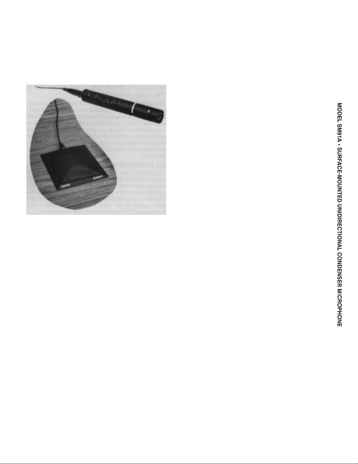
The SM91A consists of a small, rugged, surfacemounted microphone finished in professional durable
matte-black
enamel, a 7.6 m (25 ft) small diameter twoconductor shielded interconnecting cable with two
3-socket miniature Switchcraft connectors; and the
preamplifier
ILP-1
audio connector output.
sional
assembly with standard 3-pin profes
Features:
-
-
-
-
-
GENERAL
The
SM91A Microphone is
surface-mounted
applications. It is a professional-qual
designed specifically for
ity permanently-biased condenser microphone with a
half-cardioid
above
The SM91
pickup pattern (cardioid
the mounting surface.)
A t
ake
s a
dvantag
in the hemisphere
e of the w
ell-know
n p
rinciple that, at a barrier or boundary, sound pressure doubles
compared to its value if the boundary is removed. When
s
placed
ufficientl
y near the b
oundar
y s
urface
, a m
icrophone
has effectively 6 dB higher sensitivity and approximately 3
dB
g
reater rejectio
n o
f rando
m b
ackgroun
d n
oise.
Because of its half-cardioid polar pattern, the
SM91A surface-mounted microphone discriminates
against sounds originating from the rear, suiting the
SM91A
for conditions where an omnidirectional pattern
makes other surface-mounted microphones impractical.
The intrinsic unidirectionality of the SM91A can be
a
great benefit when it is desirable to isolate a particular
vocalist, instrument, or group from the rest of an ensemble being recorded. Because of a cardioid pickup
pattern, no physically isolating barriers are required,
and
directionality is maintained to low frequencies.
The SM91A can be used for individual instrument
pickup,
e.g., mounted inside the lid of a grand piano or
on the floor next to a bass drum. Experimental placement
and critical listening will help to determine the best
location
for any particular purpose or ef
fect desired.
• Wide flat frequency response for faithful sound reproduction
•
High sensitivity
across the audio spectrum
, low self-noise
-
• V
ery low distortion and high output clipping level
• Half-cardioid polar pattern minimizes pickup from
rear of microphone, permits aiming microphone,
toward performers and away from audience, or
e.g.,
toward
singers and away from instruments
•
Low susceptibility to RFI,
electrostatic and electro
magnetic hum
• Extremely
and
• Switch-selectable
off
permits tailoring response to suit conditions
•
Switch selectable preamp gain of 0 or +10 dB
• Accepts phanto
of
wide v
• Standard
preamp
rugged construction of both microphone
preamplifier for outstanding reliability
12 dB/octave low-frequency
m p
owe
r o
f 11 t
o 5
2 Vdc, p
ariet
y o
f a
mplifier
s o
r phanto
m s
3-pin male XLR-type output connector on
can
be directly connected to any 3-pin fe
male XLR-type phantom-powered input
• Low profile and matte black finish for unobtrusive
appearance on-camera or onstage; on floor,
ceiling, wall, or lectern
• Usable over very wide range of temperature and hu midity
ermit
upplies
table,
cut
s u
-
-
se
-
Copyright 1993, Shure Brothers Inc.
27A2669(MC)
Printed in U.S.A.
Page 2
SPECIFICATIONS
Type
d c
Cardioi
ondenser (electre
t b
ias) for surfac
e m
ounting
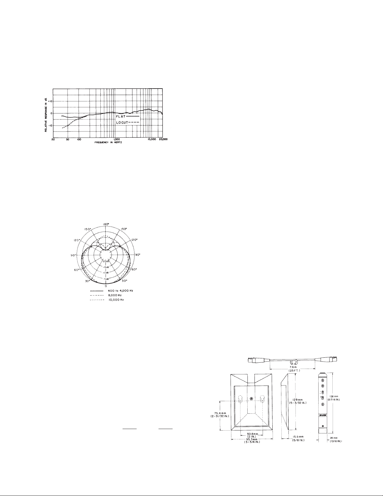
Frequency Response
20 to 20,000 Hz (see Figure 1)
TYPICAL FREQUENCY RESPONSE
(measured at 30o incidence to infinite surface)
FIGURE 1
Polar Pattern
Half-cardioid
(cardioid in
hemisphere above mounting
surface), uniform with frequency, symmetrical about
axis (see Figure 2)
TYPICAL POLAR P
ATTERN
FIGURE 2
Output Impedance
Rated at 150
Recommended minimum load impedance: 800
(May
be used with loads as low as 150 Ω with reduced
clipping
Output
at
Level
30o incidence to flat surface)
Open Circuit V
0
dB = 1 V
Ω (90 Ω
actual)
level)
(at 1,000 Hz, measured
oltage
.
. . . . . . . .
/µbar
Ω
with sound source
–71.5 dB (0.27 mV)
Preamplifier Output Clipping Level (at 1,000 Hz, less
than
0.1% THD)
GAIN
800 Ω load
150 Ω load
.
. . . . . . . . . . . . . .
.
. . . . . . . . . . . .
–13.0 dBV –21.0 dBV
0
0 dBV
(1.0
V)
+10
–7.0 dBV
(0.45 V)
.
(0.22 V) (0.09 V)
Maximum SPL
(at 1,000 Hz, less than 1% THD)
800 Ω load
ILP-1 gain set at 0 dB
ILP-1
gain set at +10 dB
150 Ω
load
ILP-1 gain set at 0 dB
ILP-1
gain set at +10 dB
Electromagnetic
Hum Pickup
.
. . . . . . . . . . . . .
.
. . . . . . . . . .
.
. . . . . . . . . . . . .
.
. . . . . . . . . .
(maximum)
–0.5 dB equivalent SPL in 1 mOe field (60 Hz)
Preamplifier Controls
Selectable Low-Frequency Response: Flat/Low Cut
(12
dB/octave rollof
f below 80 Hz)
Selectable Gain: 0/+10 dB
Output Noise
25.5 dB SPL, A-weighted
32 dB SPL, C-weighted
28.5 dB SPL per DIN 45 405
Signal-to-Noise Ratio
68.5 dB re 94 dB SPL
Dynamic Range
121 dB (800 Ω load, gain set at 0 dB)
Phasing
Positive pressur
age
o
n pin 2 r
e on d
elativ
iaphrag
e t
o pin 3 o
m p
f p
roduce
ream
p o
s p
ositive volt-
utpu
t c
Power
to 52 Vdc phantom (simplex) voltage
11
(operational
down to 9 Vdc with reduced clipping level); current
drain
2.2 mA at 52 Vdc, 1.8 mA at 1
1 Vdc
Case
Microphone: Matte black enamel die-cast base and
perforated steel grille with replaceable or cleanable
fine
mesh screen and foam pad wind/dirt barrier
Preamplifier: Matte black enamel finished steel
Cable
7.6
m (25
ft) two-conductor shielded, small diameter
with Switchcraft Tini (Q.G.) 3-pin (female) connector
on
each end
Environmental Conditions
Operating Temperature: –18 to 57o C (0 to 135o F)
Storage T
emperature: –29 to 74o C (–20 to 168o F)
Relative Humidity: 0 to 95%
Dimensions
See Figure 3
OVERALL DIMENSIONS
FIGURE 3
146.5 dB
136.5 dB
129.5 dB
1
18.5 dB
onnector
,
2.
Page 3

Net W
eight
Microphone: 280 g (9.9 oz) less cable
ILP-1 Preamplifier: 170 g (6 oz)
LOCATION
To maintain the flattest possible low-frequency response
choose
th
and the best r
a flat s
e S
M91A
urfac
. The s
e a
urfac
ejectio
s l
arg
e can b
n o
e a
f r
s p
e a f
ando
ossibl
loor
m b
e o
, w
all
ackgroun
n w
hic
h t
, c
eilin
g o
d n
o l
r t
oise,
ocate
able.
Too small a mounting surface causes a low-frequency
rolloff beginning at the f
parable to the size of the s
rate of a
proximately
bou
t 3 dB per o
6 d
B l
owe
requenc
urface
ctav
r t
han th
y w
hos
. The r
e u
nti
l i
t r
e mid- and h
e w
avelengt
ollof
f c
eache
s a p
igh-frequenc
h i
ontinue
latea
s c
s a
u a
y r
om-
t a
p-
esponse. In a similar fashion, too small a mounting surface
decreases
the r
ejectio
n o
f l
ow-frequenc
y b
ackgroun
d n
oise.
MOUNTING
The
SM91A can be permanently mounted to a
lectern,
tabletop, floor, ceiling, or wall using two No. 6 screws located 50.1 mm (2 in.) apart. The location of two keyhole
slots in the base of the microphone is marked on the
nameplate. Cut through the marked slots before sliding
the
base onto the screws.
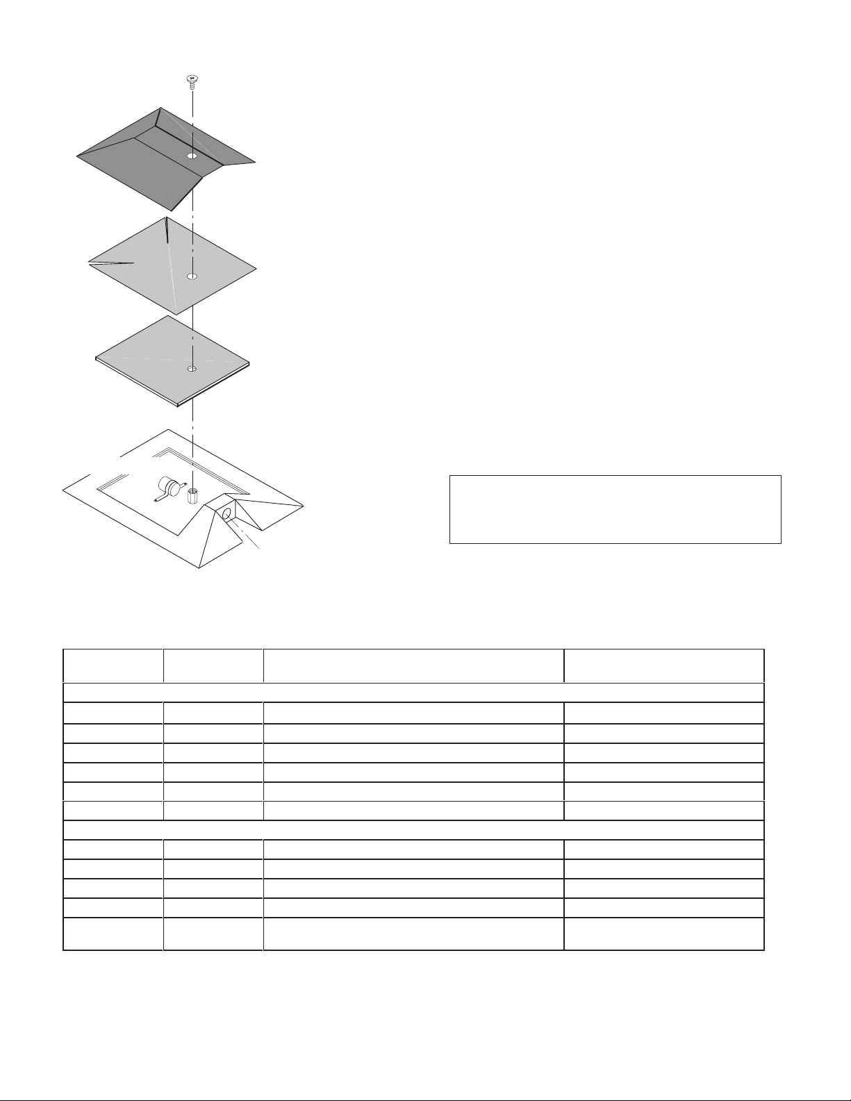
CLEANING
When the microphone is located in a dusty environment, periodic cleaning may be desirable. This can be
easily
accomplished by removing
on the grille, and lifting
of
f the grille, the fine mesh screen,
the Phillips-head screw
and the foam pad. Clean the fine stainless steel mesh
screen
by washing it in soapy water. Dry
replace
the
the foam pad, screen, and grille. Fasten firmly with
Phillips screw
.
it thoroughly
, and
DISASSEMBLING AND REASSEMBLING THE ILP-1
1. At the XLR-3 end of the preamplifier, turn the slotted
head setscrew fully inward (counterclockwise), and
use
a long-nose pliers to withdraw the connector from
the
case.
2. Unsolder
the three lead wires from the XLR-3 board.
3. Remove all four Phillips-head screws from the ILP-1
case
(three on the switch side, one on the back).
4. Grasp
board
the
case.
the end
cap and withdraw the cap assembly
assembly
, and
connecting wires and jacks from
, pc
REASSEMBLY
1. Make
2.
sure the pc board is seated in the slot
cap
and that no wires are pinched.
With the XLR-3
connecting wires foremost, feed the
of the end
endcap-board assembly into the case. Again, take
care
not to pinch the wires connecting the board to
the
endcap.
3. Rotate the assembly until the four holes for Phillips
screws
4.
Replace the four Phillips screws.
5. Resolder
board
line up with the holes in the case.
the three lead wires to the back of the XLR-3
as shown below
.
-
MOUNTING CLAMPS, PREAMPLIFIER
FIGURE 4
The supplied mountin
preamplifier in p
3). Us
e e
ithe
r one o
application.
To a
lac
voi
g c
lamp
e i
n p
ermanent installation
r two c
lamp
s d
d g
roun
d l
oop
s and hum, a
s are i
ntende
ependin
g o
d t
o hold t
s (see F
n l
ocatio
voi
d g
he
igure
n a
nd
rounding the microphone preamplifier housing to metal building
structures. Th
rectly
into a f
lus
e I
LP-
h m
1 p
reamplifie
ounte
d c
onnector i
r can a
lso be p
f d
esired.
lugge
d d
INTERCONNECTING CABLE
One
7.6 m (25 ft) cable
SM91A
cess
Microphone to the ILP-1 Preamplifier
to the controls located in the preamplifier
is supplied for connecting the
. T
o retain ac
, it is some
times desirable for the units to be located a greater distance
apart. Up to 15 m (50 ft) of additional cable can be
used
between the
plifier
with no loss in response or output.
SM91A Microphone and ILP-1 Pream
i-
-
-
-
3.
RED
WIRING T
2
O XLR-3 PC BOARD TERMINALS
1
3
BLACK
BLUE
FIGURE 5
6. Replace
case
the case. Take care not to engage the butterflyshaped
seating
7. Insert
setscrew
screw
the XLR-3 board-connector assembly in the
lining up the key in the
connector with the slot in
ground contact in the key slot as it will prevent
the connector properly
the connector fully in
.
the case until the slotted
can be seen in the case hole; tighten the set
firmly by turning it clockwise.
-
Page 4
PHILLIPS-HEAD SCREW
PERFORATED MET
GRILLE
AL
To paint the base:
1. Remove
of
and
2. Wrap
ment to perforate an opening for the screw, and replace
3.
Replace and tighten the screw
4. Carefully
the flat-head Phillips screw in
the perforated metal grille. Lift of
foam pad.
the grille in thin plastic film, use a pointed instru
the wrapped grille on the microphone.
paint the microphone base and screw
with the desired color. To avoid getting any paint on
STAINLESS FINE-MESH
SCREEN
the
connector
mating
plug to it.
5.
Allow the paint to dry thoroughly
, either mask it thoroughly or connect a
To paint the metal grille:
1. Once
FOAM PAD
2. Remove
3.
4. Use fine sandpaper to remove any paint that may
CARTRIDGE
BASE
CONNECTOR
5. Before replacing the grille, check that the fine-mesh
MICROPHONE PARTS
FIGURE 6
REPLACEMENT P
Reference
Designation
ARTS
Part
Number Description
Preamplifier
A1 90B4220
A2 90HZ2600
P1 95A8077
P2 90HV2600 XLR-3
MP1 66A264
MP2 80A476
ILP-1 Preamplifier Assembly
Pc Board Assembly
Plug Assembly
M C
, Male, Mini
onnector an
d P
Preamp Switch Cover
Mounting Clamp
Microphone
A3 98A144
A4 R129
Microphone Assembly
Cartridge and Impedance Converter
MP3 53A1879B Grille None
MP4 37A147
W1 C107
Inner Screen
Cable Assembly
, 7.6 m (25 ft), T
Shielded, Small Diameter
6. Replace
c B
oar
d A
again,
remove the flat-head Phillips screw in the
top center of the plastic-wrapped perforated metal
grille.
Lift of
f the grille.
the plastic wrap and paint the outside of the
grille. Take care to use a thin layer only; do not fill the
perforated
holes with paint.
Allow the paint to dry thoroughly
have
adhered
edging
around the screw-hole.
to the outer edges of the grille and the
IMPORTANT
For proper shielding it is extremely important to
maintain electrical continuity between the grille
and
the metal base.
screen is clean. Otherwise, wash it in soapy water.
Rinse
and dry it thoroughly
the foam pad, mesh screen, and perforated
grille; and fasten securely with the Phillips screw
None
None
Switchcraft, TB3M T
ssembly None
None
All States 3/4-HNB
None
None
None
wo Conductor
,
None
the top center
f the grille, screen,
-
.
head
.
.
.
.
Commercial Alternate
ini
4.
Page 5
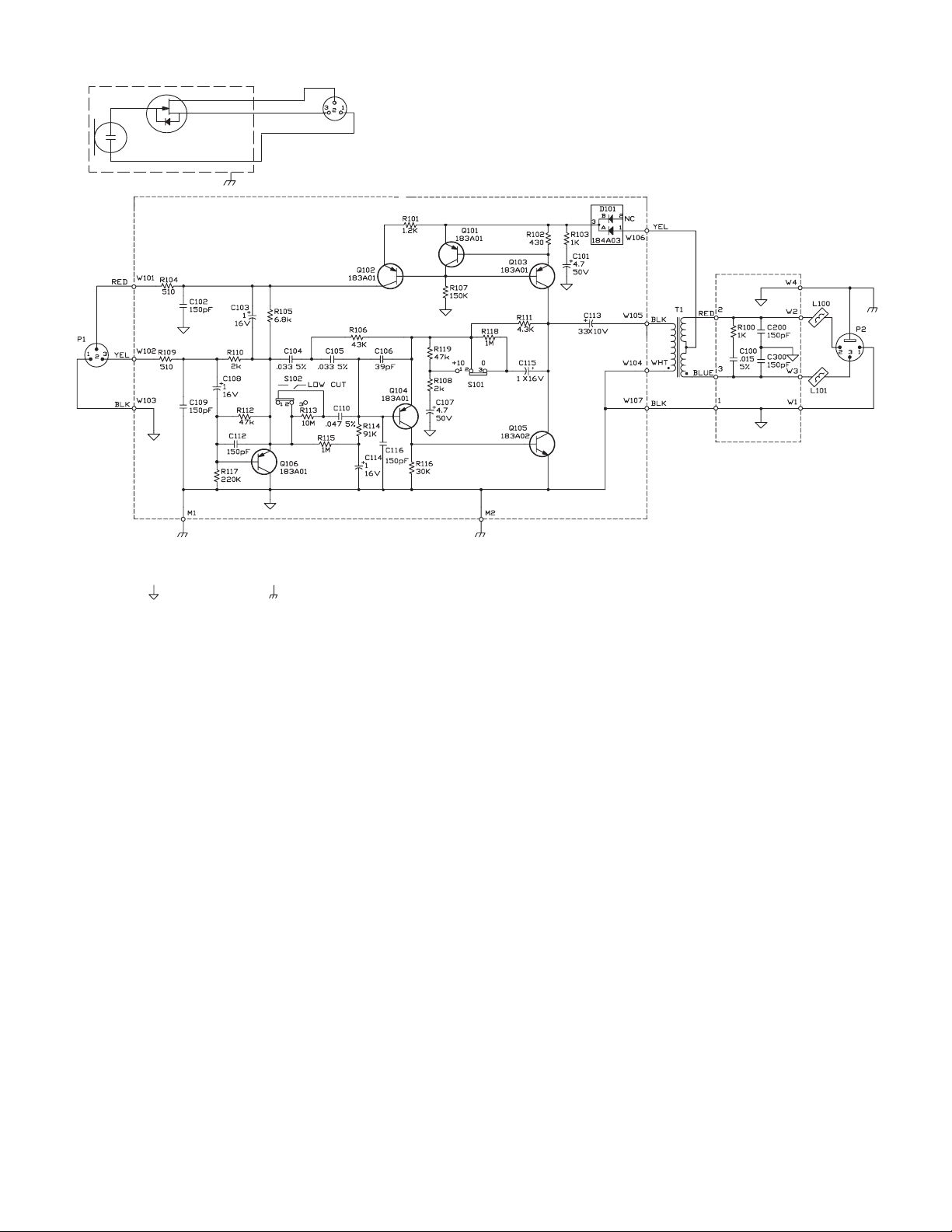
CONDENSER
CARTRIDGE
D
G
S
RED
BLUE
BLACK
GAIN
NOTES:
1 UNLESS OTHERWISE SPECIFIED, ALL RESISTORS ARE 1/8 WATT
2 UNLESS OTHERWISE SPECIFIED, ALL CAPACITORS IN F, 10%, 50 V OR GREATER. ELECTROLYTIC CAPACITORS SHOWN IN F
3 THE FOLLOWING SYMBOLS DENOTE:
PC BOARD GROUND CHASSIS GROUND.
.
, 5%.
GRN
OR
BROW
N
OR
X VOLTS, 20%.
CIRCUIT
FIGURE 7
DIAGRAM
5.
 Loading...