

GENERAL
The Shure Model SM85 is a professional-quality,
hand-held, unidirectional condenser microphone
designed for the most demanding applications in sound
reinforcement, broadcasting and studio recording. It is
especially suitable for applications requiring wide frequency response, low distortion characteristics, very
low RF susceptibility, and reliable operation over a wide
range of temperature and humidity extremes. The
SM85
makes optimum use of proximity effect to give the performer control of low-frequency sound, from the warm
intimacy of close
normal-to-distant
miking to the natural sounds of
miking. The SM85 also features an integral wind and pop filter, a high-frequency presence
peak, a controlled low-frequency
rolloff, and an effective shock mount for reduced stand and handling noise.
The case is constructed of aluminum for light weight
and ruggedness, with a steel grille and durable black
finish.
IS
The SM85
ing from an external supply or directly from sound
forcement, broadcast, or recording equipment. The
SM85 operates over an extremely wide voltage range of
11 to 52 Vdc, covering both DIN Standard 45 596 simplex
voltages of 12 and 48 volts, and the proposed 24-volt
standard.
designed for simplex (phantom) power-
rein-
SPECIFICATIONS
Type
Cardioid condenser (electret bias)
Frequency Response
50 to 15,000 Hz (see Figure 1)
The microphone is supplied with an accessory swivel
adapter. Model
and Model
SM85-LC is supplied without a cable,
SM85-CN is supplied with a 7.6m (25 ft)
TRIPLE-FLEX@ microphone cable with professional
audio connectors. Two dual-channel power supplies
(Models PSI and PSlE2) are available for providing
simplex power to the
Model
SM85
Features:
SM85.
Wide-range frequency response tailored for professional vocal applications
Built-in wind and pop filter minimizes undesirable
;+lo
z
z
D
W
>
5
:
0
-I0
20
w
1w
FREWENCY IN
lpo0 l0,OW
HERTZ
wind and breath sounds
Controlled low-frequency rolloff to reduce low-
frequency handling noise and compensate for prox-
imity effect
Polar Pattern
TYPICAL FREQUENCY RESPONSE
FIGURE
1
Transducer element shock-mounted for reduced Cardioid (unidirectional) response- uniform with frestand and handling noise
Low distortion output and wide dynamic range
characteristics for a variety of load impedances
Cardioid polar pattern, uniform with frequency and
symmetrical about axis, to provide maximum rejection and minimum coloration of off-axis sounds
D
Very low RF and magnetic hum susceptibility
D
Wide-range simplex powering includes DIN 45 596
voltages of 12 and 48 Vdc
Rugged construction for outstanding reliability
Field-usable over wide range of temperature and
humidity conditions
quency, symmetrical about axis (see Figure
Output Impedance
Rated at 150 ohms (85 ohms actual)
Recommended minimum load impedance: 800 ohms
(May be used with loads as low as 150 ohms with
reduced clipping level)
Output Level
Open Circuit Voltage
(at 1,000 Hz)
.
. . . . . .
. .
. .
-74
(0 dB = 1 volt per microbar)
Clipping Level
800-ohm Load . . . .
150-ohm Load
(at 1,000 Hz)
.
. . . . . . . . . . . .
. . . . . .
. .
. . . . . .
. . .
-
-
15 dBV
2)
dB (0.2 mV)
4
dBV (0.63V)
(0.18V)
20,000
c
Z
e
n
rn
?
$
o
0
g
E
a
0
gum
g
r
222 HARTREY
Copyrtght
27A1992
1983. Shure Brothers
(CK)
AVE
.
EVANSTON
Inc
IL
60204
U
S A AREA
CODE 3121866-2200
CABLE
SHUREMICRO
TWX
910-231-0048
TELEX
Printed In
72-4349
U.S.A.
rn
VI
0
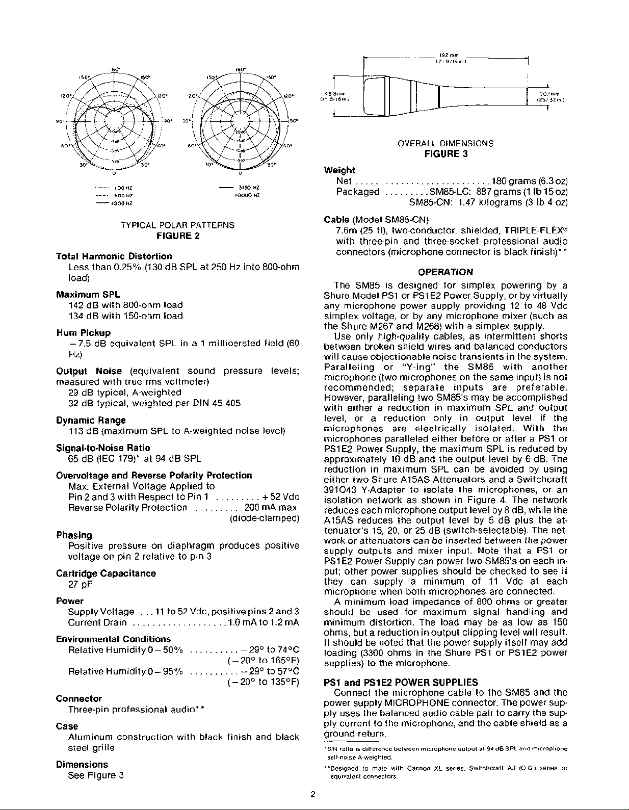
TYPICAL POLAR PATTERNS
FIGURE 2
Total Harmonic Distortion
Less than 0.25% (130 dB SPL at 250 Hz into 800-ohm
load)
Maximum SPL
142 dB with 800-ohm load
134 dB with 150-ohm load
Hum Pickup
-7.5 dB equivalent SPL in a 1 millioersted field (60
Hz)
Output Noise
measured with true
(equivalent sound pressure levels;
rms voltmeter)
29 dB typical, A-weighted
32 dB typical, weighted per DIN 45 405
Dynamic Range
113 dB (maximum SPL to A-weighted noise level)
Signal-to-Noise Ratio
65 dB (IEC 179)* at 94 dB SPL
Overvoltage and Reverse Polarity Protection
Max. External Voltage Applied to
Pin 2 and 3 with Respect to Pin
Reverse Polarity Protection
.........
.........
+
,200 mA max.
1
(diode-clamped)
Phasing
Positive pressure on diaphragm produces positive
voltage on pin 2 relative to pin 3
Cartridge Capacitance
27 pF
Power
Supply Voltage
Current Drain
..
.ll
to 52 Vdc, positive pins 2 and 3
..................
.1.0 mA to 1.2 mA
Environmental Conditions
Relative Humidity 0-50°/o
..........
-2g0 to 74OC
(-20' to 165OF)
Relative Humidity 0-95%
..........
-2g0 to 57OC
(-20' to 135OF)
Connector
Three-pin professional audio**
Case
Aluminum construction with black finish and black
steel grille
Dimensions
See Figure 3
52 Vdc
OVERALL DIMENSIONS
FIGURE
3
Weight
Net
..........................
Packaged
.........
SM85-LC: 887 grams (1 lb 15 oz)
,180 grams (6.3 oz)
SM85-CN: 1.47 kilograms (3 Ib 4 oz)
Cable
(Model SM85-CN)
(25 ft), two-conductor, shielded, TRIPLE-FLEX@
7.6m
with three-pin and three-socket professional audio
connectors (microphone connector is black finish)**
OPERATION
The SM85 is designed for simplex powering by a
Shure Model
PSI or PSlE2 Power Supply, or by virtually
any microphone power supply providing 12 to 48 Vdc
simplex voltage, or by any microphone mixer (such as
the Shure M267 and
M268) with a simplex supply.
Use only high-quality cables, as intermittent shorts
between broken shield wires and balanced conductors
will cause objectionable noise transients in the system.
Paralleling or "Y-ing" the
SM85 with another
microphone (two microphones on the same input) is not
recommended; separate inputs are preferable.
However, paralleling two
SM85's may be accomplished
with either a reduction in maximum SPL and output
level, or a reduction only in output level if the
microphones are electrically isolated. With the
microphones paralleled either before or after a
PSI or
PSI E2 Power Supply, the maximum SPL is reduced by
approximately 10 dB and the output level by 6 dB. The
reduction in maximum SPL can be avoided by using
either two Shure
A15AS Attenuators and a Switchcraft
391Q43 Y-Adapter to isolate the microphones, or an
isolation network as shown in Figure 4. The network
reduces each microphone output level by 8 dB, while the
A15AS reduces the output level by 5 dB plus the attenuator's 15, 20, or 25 dB (switch-selectable). The network or attenuators can be inserted between the power
supply outputs and mixer input. Note that
a
PS1 or
PSI E2 Power Supply can power two SM85's on each input; other power supplies should be checked to see if
they can supply a minimum of 11 Vdc at each
microphone when both microphones are connected.
A minimum load impedance of 800 ohms or greater
should be used for maximum signal handling and
minimum distortion. The load may be as low as 150
ohms, but a reduction in output clipping level will result.
It
should be noted that the power supply itself may add
loading (3300 ohms in the Shure
PS1 or PSlE2 power
supplies) to the microphone.
PSI and PSlE2 POWER SUPPLIES
Connect the microphone cable to the SM85 and the
power supply MICROPHONE connector. The power supply uses the balanced audio cable pair to carry the supply current to the microphone, and the cable shield as a
ground return.
'SIN ratio is difference between m~crophone output at
self-noise A-weighted.
"Designed to mate with Cannon XL series, Switchcraft
equivalent connectors.
94
dB SPL and microphone
A3
(Q
G.)
series or

FROM
MIC
I
FROM
2
MIC
ALL
RESISTORS
232
OHMS,
ISOLATION NETWORK
FIGURE
Connect the power supply OUTPUT connector to a
low-impedance microphone input of a mixer, audio console or tape recorder. A second SM85 may be connected
to the remaining power supply channel in a similar
manner.
ALTERNATE POWER SOURCES
As an alternate to the PSI or PSI E2 power supplies,
the SM85 can be simplex-powered from virtually any
mixer, audio ccnsole or tape recorder using one of the
wiring configurations shown in Figures 5 and 6. Any
well-filtered voltage available in the mixer from 12 to 48
Vdc may be used. The graph in Figure
of values which can be used for resistor
SM85 is used with a regulated power supply. The
tolerance of the resistors (2R) shown in Figure 5 should
O/O
be 1
absolute value is not critical. Note that the two-resistor
simplex power supply (Figure
4R,
SM85. If the combined parallel load is below 800 ohms,
the transformer configuration (Figure 6) is recommend-
ed, and if the combined load is 150 ohms or less, it must
be used.
or better to assure close matching, although the
paralleled with the mixer input impedance, to the
INPUT FROM
MICROPHONE
n
4
5)
presents a load equal to
I0/o
7
shows the range
R when the
OUTPUT
TO
MIXER
RESISTOR R VALUES
FIGURE
If the power supply is unregulated, the power supply
voltage may drop when the SM85 is connected to it, due
to the added load. To account for this load, the value of
R may be determined as follows. Connect a variable
resistance (or resistor substitution box) in series with a
10-kilohm,
resistor to ground and the free end of the variable
resistor to
resistor until 12 to 36 volts is measured across the
resistor. Note the actual dc supply voltage and the value
of the variable resistor. Verify that the resistor value
falls within the indicated range on the graph of Figure
The value of the variable resistor is the appropriate
resistance
Figure 5 is to be used, double the resistor value
Voltages as low as 10 Vdc minimum as measured at the
microphone connector are acceptable. The nominal current drain at 10 Vdc is 1.1
rent a power supply must be able to deliver for proper
operation.
For example, in mixers with 30 Vdc power supplies,
the value of 2R for the configuration in Figure
3.6k. Two 3.6k resistors should be closely matched (2%
or better), and may be mounted externally with the
end connected to the 30V terminal. The resistors may
also be mounted internally (such modifications should
be performed by qualified service personnel only).
A convenient method of battery-powering the SM85
using two 9-volt batteries is shown in Figure 8. Note
10% resistor. Connect the free end of the 10k
B
+
of the power supply. Adjust the variable
R for use in Figure 6. If the configuration in
7
10k
7.
(2R).
mA. This is the minimum cur-
4
could be
B+
C
TWO-RESISTOR CONFIGURATION
FIGURE
INPUT FROM
MlCROPHObJE
CENTER-TAPPED TRANSFORMER
CONFIGURATION
FIGURE
5
C
R
6
OUTPUT
TO
MIXER
FROM
INPUT
MICROPHONE
BATTERY POWER SUPPLY
FIGURE
that this circuit can only be used with balanced, floating
(ungrounded), transformer-coupled input mixers such
as the Shure M67 or
tolerance or better to assure close matching. With new
batteries, this supply will operate an SM85 for approximately 200 hours.
SE30. The resistors should be
8
OUTPUT
MIXER
TO
1
O/O

CAPACITOR
CARTRIDGE
BALANCED
TRANSFORMER
'
RESPONSE
FILTER AMPLIFIER
-
BLOCK
WIND NOISE
The SM85 has an integral wind and pop filter which
provides excellent protection against most wind and
breath noise. Under adverse conditions, such as a windy day outdoors, or close proximity to a "problem"
vocalist, the optional foam windscreen can be used.
CIRCUIT DESCRIPTION
A block diagram of the SM85 is shown in Figure 9.
The capacitor cartridge is followed by a field-effect transistor (FET) impedance conversion stage. The FET output drives an active low-frequency
filter. The filter output from the compound transistor,
Class A, emitter-follower amplifier is
coupled, providing a balanced output to the RFI protection filter at the microphone connector. An active
constant-current, power supply circuit regulates the
simplex voltage, allowing the
very wide range of voltages. A reverse voltage protection diode guards against
ment. The circuit contains five semiconductors to provide low noise, low distortion, wide frequency response,
and ultra-reliable operation over a very wide range of
operating conditions. Screen and Grille RK214G
miswired cables and equip-
rolloff (high-pass)
transformer-
SM85 to operate over a
SERVICING
TROUBLESHOOTING
~ue
to the high packing density and circuit complexi-
ty of the SM85, only basic servicing is recommended.
The following steps should be taken if problems arise.
1. Check the power supply output voltage to the
microphone. For the Shure
be 21.5 + 1.5 Vdc open circuit.
2. Check the voltage on microphone connector pins 2
and 3 (at back of connector; cable connector of one year from date of purchase. Please retain proof
disassembled from shell but connected to of purchase date. This guarantee includes all parts and
microphone). The voltage at pins 2 and 3 with labor. This guarantee is in lieu of any and all other
reference
to pin 1 should be between 10 and 48 Vdc. guarantees or warranties, express or implied, and there
PSI or PSI E2, this should
DISASSEMBLY
See Figure 10.
CLASS A
COMPOUND
DIAGRAM
FIGURE
-
REGULATOR/
REVERSE
9
The overall dimensions shall be 192 mm (7-9116 in.) in
length by 48.8 mm (1-15116 in.) in diameter. The handle
diameter shall be 20.1
be 180 grams (6.3 oz).
The microphone shall be capable of being powered by
a simplex (phantom) power supply with an output of
to 52 Vdc, or by a mixer, audio console or tape recorder
capable of supplying 11 to 52 Vdc.
The microphone shall be a Shure Model
FURNISHED ACCESSORY
Swivel Adapter
.............................
OPTIONAL ACCESSORIES
Simplex Power Supply
Switch-Selectable Attenuator
Isolation Mount
Windscreen
...............................
REPLACEMENT PARTS
Cartridge and Shock Mount
Amplifier .90A3024
Case*
RFI Filter and Plug Element
Cable (SM85-CN only)
*Includes RFI Filter and Plug Element.
...............................
..................................
GUARANTEE
This Shure product is guaranteed in normal use to be
free from electrical and mechanical defects for a period
shall be no recovery for any consequential or incidental
damages.
mm (25132 in.). The weight shall
SM85.
.................
.PSI, PSI E2
................
............................
A85WS
.........................
...................
...............
90A3029
.90A3622
.......................
11
.A57E
A15AS
.A53M
R112
.C25E
The microphone shall be a condenser microphone
ARCHITECTS' SPECIFICATIONS
with a frequency response of 50 to 15,000 Hz. It shall
have a cardioid directional characteristic, with
cancellation at the sides of 6 dB and a minimum
cancellation at the rear of 15 dB at 1 kHz. The
microphone shall have a rated output impedance of 150
ohms for connection to microphone inputs of 150 ohms
or higher. The open circuit voltage shall be -74
mV) (0 dB equals 1 volt per microbar).
dB (0.2
SHIPPING INSTRUCTIONS
Carefully repack the unit, have it insured, and return it
prepaid to:
Shure Brothers Incorporated
Attention: Service Department
222 Hartrey Avenue
Evanston, Illinois 60204
If outside the United States, return the unit to your
dealer or Authorized Shure Service Center for repair.
The unit will be returned to you prepaid.

FIGURE
10

SOUND OF THE PROFESSIONALS@
 Loading...