

Shure SM81 User Manual
MODEL SM81
UNIDIRECTIONAL CONDENSER MICROPHONE
The Shure Model SM81 is a high-quality, unidirectional
condenser
fessional applications in studio recording, broadcasting, and
sound
quiring
tortion characteristics, very low RF susceptibility, and reliable
operation over a wide range of temperature and humidity
extremes.
a stainless steel screen, and finished in durable vinyl paint.
uator lock, windscreen, and carrying/storage case. It is supplied
pop-filter
A81WS), a compact, lightweight microphone stand (Model
S15)
crophone
power supply (Model PS1A). An alternative omnidirectional
cartridge (Model R104A) is also available.
microphone designed for the
reinforcement. It is especially suitable
extremely wide frequency
The case is constructed
The microphone is furnished with a swivel adapter, atten-
without cable. A
grille (Model A81G), a heavy-duty windscreen (Model
capable of extension to 4.3 m (14 ft), a versatile stereo mi
adapter (Model A27M), and a dual-channel phantom
vailable accessories are a highly ef
most demanding pro
for applications re
response, low noise and dis
of steel for ruggedness, with
ficient
Model SM81 Features:
•
Wide-range, frequency response for exceptionally accu-
rate recording and sound reinforcement applications
•
Low noise and high output clipping level characteristics
•
Low distortion characteristics over the entire audio spec-
trum for a wide range of load impedances
•
Cardioid polar pattern, uniform with frequency and sym-
metrical about axis, to provide maximum rejection and
minimum coloration of off-axis sounds
•
Very low RF susceptibility
•
Selectable
rolloff
•
10 dB attenuator accessible without disassembly; lockable
in either position
•
Wide-range phantom powering includes DIN 45 596 volt-
ages of 12 and 48 Vdc
•
Rugged construction for outstanding reliability
•
Field-usable
conditions
low-frequency response: flat, 6 or 18
over wide range of temperature and
dB/octave
humidity
Shure
Brothers Incorporated
222 Hartrey A
venue
Evanston IL 60202-3696 U.S.A.
Model SM81 User Guide
SPECIFICATIONS
Type
Cardioid
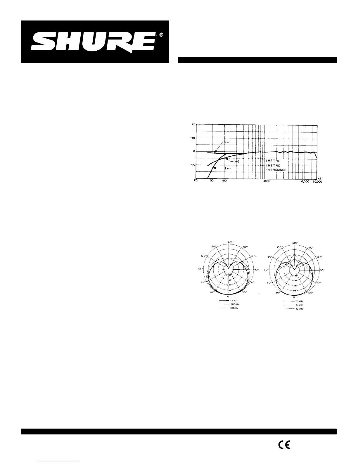
Frequency Response
20 to 20,000 Hz (see Figure 1)
-
-
-
Polar Pattern
cy, symmetrical about axis (see Figure 2)
-
Output Impedance
Output
Open Circuit Voltage –65 dB (0.56 mV).
Equivalent Power Level –40.5 dB.
Clipping
800 Ω Load –4 dBV (0.63 V).
150 Ω
TYPICAL FREQUENCY RESPONSE
FIGURE 1
Cardioid
(unidirectional) response—uniform with frequen
TYPICAL
POLAR P
FIGURE 2
Rated at 150 ohms (85 Ω actual)
Recommended minimum load impedance: 800 Ω (May
be used with loads as low as 150 Ω with reduced clipping level)
Level (at 1,000 Hz)
. . . . . . . . . . . . . . . .
. . . . . . . . . . . . . . . . . . . . .
Level (at 1,000 Hz)
. . . . . . . . . . . . . . . . . . . . . . . . .
Load
–15 dBV (0.18 V).
. . .
. . . . . . . . . . . . . . . . . . . .
-
ATTERNS
(0 dB = 1 volt per µbar)
(0 dB = 1 milliwatt per 10 µbars)
1996, Shure Brothers Inc.
27A2916
(P
A)
Printed in U.S.A.
T
otal Harmonic Distortion
Less than 0.5% (131 dB SPL at 250 Hz into 800 Ω
Maximum
SPL (at 1,000 Hz)
136 dB (attenuator at 0); 146 dB (attenuator at 10)
with 800 Ω
load
128 dB (attenuator at 0); 138 dB (attenuator at 10)
with 150 Ω
Hum
Pickup
load
–3 dB equivalent SPL in a 1 moe field (60 Hz)
Output
Noise
(equivalent sound pressure levels; measured
with true rms voltmeter)
16 dB typical, A-weighted
19 dB typical, weighted per DIN 45 405
Signal-to-Noise Ratio
78 dB (IEC 651)* at 94 dB SPL
Overvoltage
Max. External V
to Pins 2 and 3 with Respect to Pin 1 + 52 Vdc.
and Reverse Polarity Protection
oltage Applied
. . . . . . .
Reverse Polarity
Protection 200 mA max. (diode-clamped).
. . . . . . . . . . . . .
Phasing
Positive pressure on diaphragm produces positive voltage
on pin 2 relative to pin 3
Cartridge
Capacitance
54 pF
LP
Response Switch
Flat,
–6 dB/octave below 100 Hz, –18 dB/octave below 80
Hz
Attenuator
Switch
0 or 10 dB (120 pF)
Power
Supply V
Current Drain 1.0 mA to 1.2 mA.
oltage
. . . . . .
11 to 52 Vdc, positive pins 2 and 3.
. . . . . . . . . . . . . . . . . . . . . .
Environmental Conditions
Relative Humidity 0–50%
. . . . . . . . . . . . . . .
– 29
to 74 C.
(–20 to 165 F)
Relative Humidity 0–95%
. . . . . . . . . . . . . .
– 29
to 57 C.
(–20 to 135 F)
Connector
Professional 3-pin audio**
Case
Steel
construction with metallic vinyl paint finish and stain
less steel screen
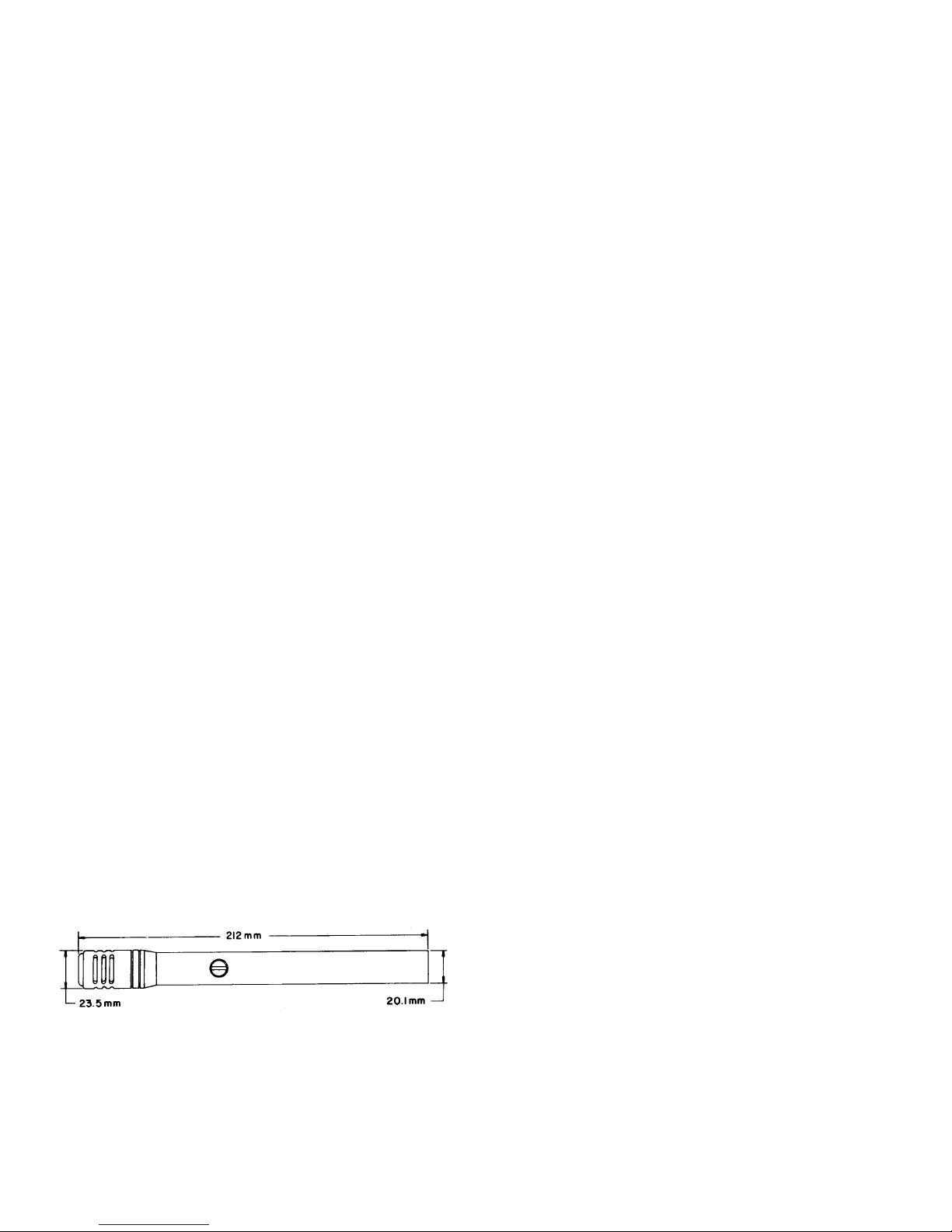
Dimensions
See Figure 3
load)
Weight
Net 230 grams (8 oz).
. . . . . . . . . . . . . . . . . . . . . . . . . . . . . . .
Packaged 1.2 kg (2 lb 10 oz).
*S/N
ratio is dif
phone
**Designed
equivalent
. . . . . . . . . . . . . . . . . . . . . . . . .
ference between microphone
self-noise A-weighted.
to mate with Cannon XL series,
connectors.
output at 94 dB SPL and micro
Switchcraft A3 (Q.G.) series or
Certification
Conforms
marking;
to European Union directives, eligible to bear
meets European Union EMC Immunity Requirements
(EN 50 082–1, 1992); RF radiated (IEC 801–3); ESD (IEC
801–2); EFT (IEC 801–4).
OPERATION
The SM81 is designed for phantom powering by Shure
Model
PS1A Power Supply
er supply providing 12 to 48 Vdc phantom voltage.
Use only high-quality cables, as intermittent shorts be-
tween
broken shield wires and balanced
extremely large noise transients in the system. Avoid ground
loops
due to grounded connector shells or the microphone case
touching other grounded metal objects. Follow generally accepted audio grounding practices.
Paralleling or “Y-ing” the SM81 with another microphone
(two microphones on the same input) is not recommended;
separate inputs are preferable. However, paralleling two
SM81’s may be accomplished with either a reduction in maximum
SPL and output level, or a reduction only in
the microphones are electrically isolated. With the microphones
the
paralleled either before or
maximum SPL is reduced by approximately 10
output level by 6 dB. The reduction in maximum SPL can be
avoided by using either two Shure A15AS Attenuators and a
Switchcraft 391Q43 Y-Adapter to isolate the microphones, or
an
isolation network as shown in Figure 4. The network
each microphone output level by 8 dB, while the A15AS reduces
the output level by 5 dB plus the attenuator’s 15, 20, or 25
dB (switch-selectable). The network or attenuators can be inserted between the power supply outputs and mixer input, or
between two microphones and a single power supply input.
Note
that a PS1A Power Supply can power two SM81’
input;
other power supplies should be checked to see if they can
supply
a minimum of 10 Vdc at each microphone when both mi
crophones are connected.
A
minimum load impedance of 800 Ω or greater should be
used
for maximum signal handling and minimum distortion. The
load
-
may be as low as 150 Ω, but a reduction in output
level will result. It should be noted that the power supply itself
may
add loading (3300 Ω in the Shure PS1A power supply) to
the microphones.
, or by virtually any microphone pow
conductors will cause
after a PS1A Power Supply
-
CE
-
output level if
,
dB and the
reduces
s on each
-
clipping
OVERALL DIMENSIONS
FIGURE 3
2
 Loading...