

Page 1
GENERAL
The Model SM7B dynamic microphone has a smooth, flat,
wide-range frequency response appropriate for music and
speech in
all professional audio applications. It features excellent shielding against electromagnetic hum generated by com
puter monitors, neon lights, and other electrical devices. The
has been updated from earlier models with an improved
SM7B
bracket design that offers greater stability. In addition to its
standard
windscreen, it also includes the A7WS windscreen
for close-talk applications.
Features
• Flat, wide-range frequency response for clean and natural
reproduction
of both music and speech
• Switchable bass rolloff and mid-range emphasis (presence
settings
boost)
• Shielded against broadband interference from computer
monitors
of
and other electrical devices—excellent rejection
electromagnetic hum
• Internal “air suspension” shock isolation virtually eliminates
mechanical
noise transmission
• A7WS windscreen included for close-up vocals or narration
• Swiveling bracket with integrated stand adapter for easy
mounting and precise microphone positioning
• Cardioid polar pattern, uniform with frequency and symmet-
about axis, to provide maximum rejection and mini-
rical
coloration of off-axis sound
mum
• Rugged construction and excellent cartridge protection for
outstanding reliability
APPLICATIONS
The exceptional performance and unique features of the
make it the outstanding choice for such applications as:
SM7B
• Recording Studio—Instrumental and Vocal
• Location Recording
• Motion Picture and Television Scoring
• Television Talk Shows and News Desks
• Radio Announcing and Production
• Narration
Model SM7B User Guide
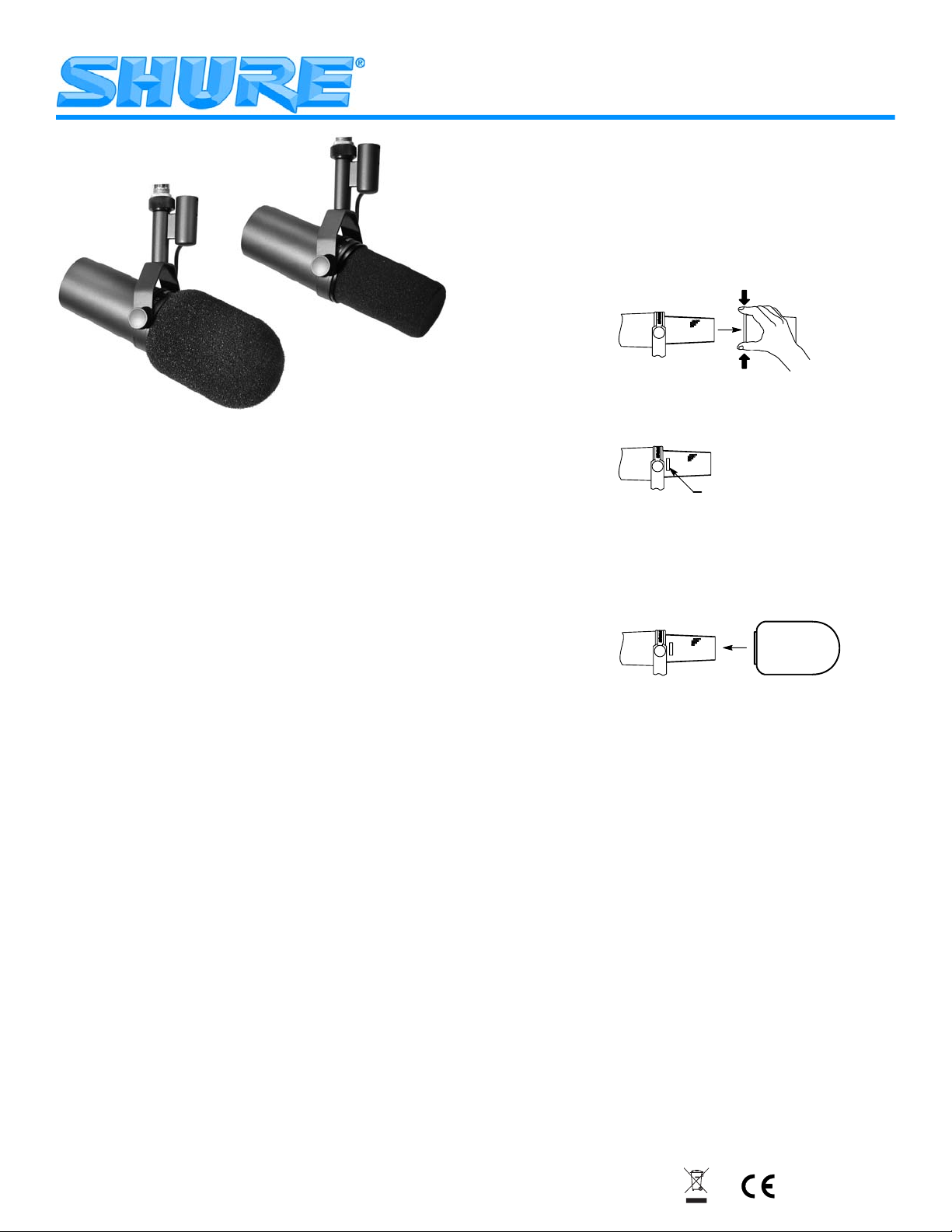
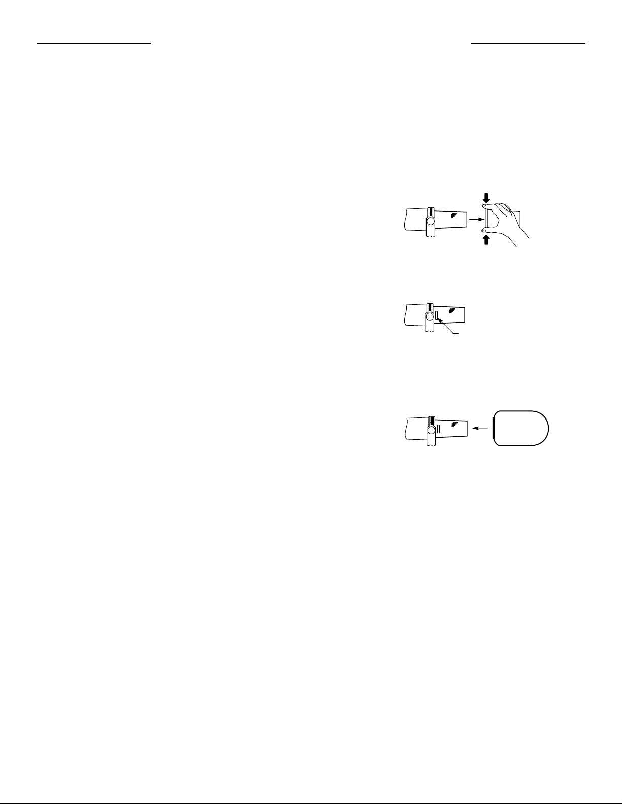
WINDSCREEN
the standard windscreen for general voice and instru-
Use
mental
applications. Use the supplied A7WS windscreen for
close-talk applications, such as voice overs or radio announcements, as it offers maximum protection from plosive
breath
noise and creates a warmer, more intimate sound.
To install the A7WS, follow these instructions:
1. To avoid tearing the windscreen during removal, grip it
m the plastic ring and the base and remove by gently
fro
pulling and twisting.
2. If desired, adhere the supplied velcro strips around the mi-
crophone grille, approximately one
the
grille (as shown above) to hold new windscreen in
place.
-
3. Install the A7WS windscreen by stretching over the velcro
strips
, then squeezing at the base of the windscreen to ad-
here to the velcro. No velcro strip inside the windscreen
needed, as the windscreen itself adheres to the velcro.
is
To remove, grip at the base of the windscreen and pull
while twisting.
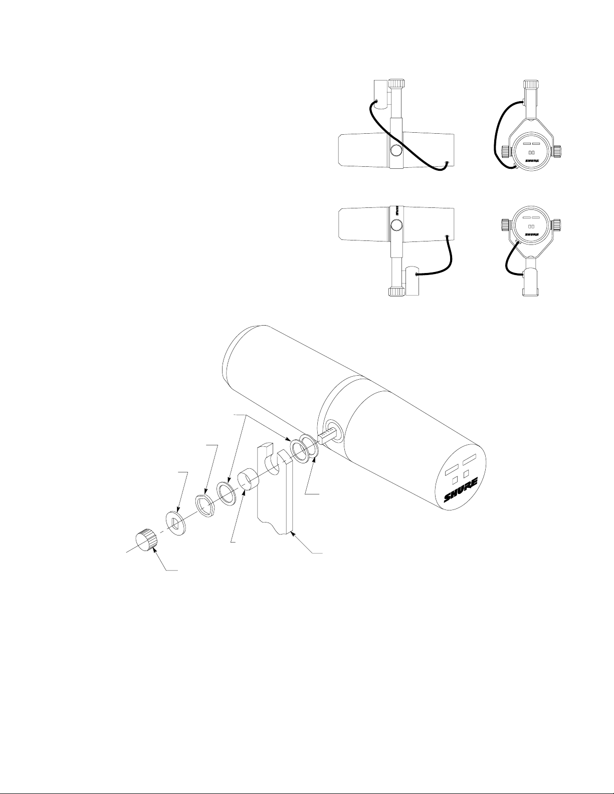
MOUNTING INSTRUCTIONS
e SM7B can be mounted on a microphone stand or hung
Th
m a boom. It is shipped in the boom mounting configuration
fro
(see Figure 1).
mounting
To set up the SM7B in the microphone stand
configuration (see Figure 2), proceed as follows:
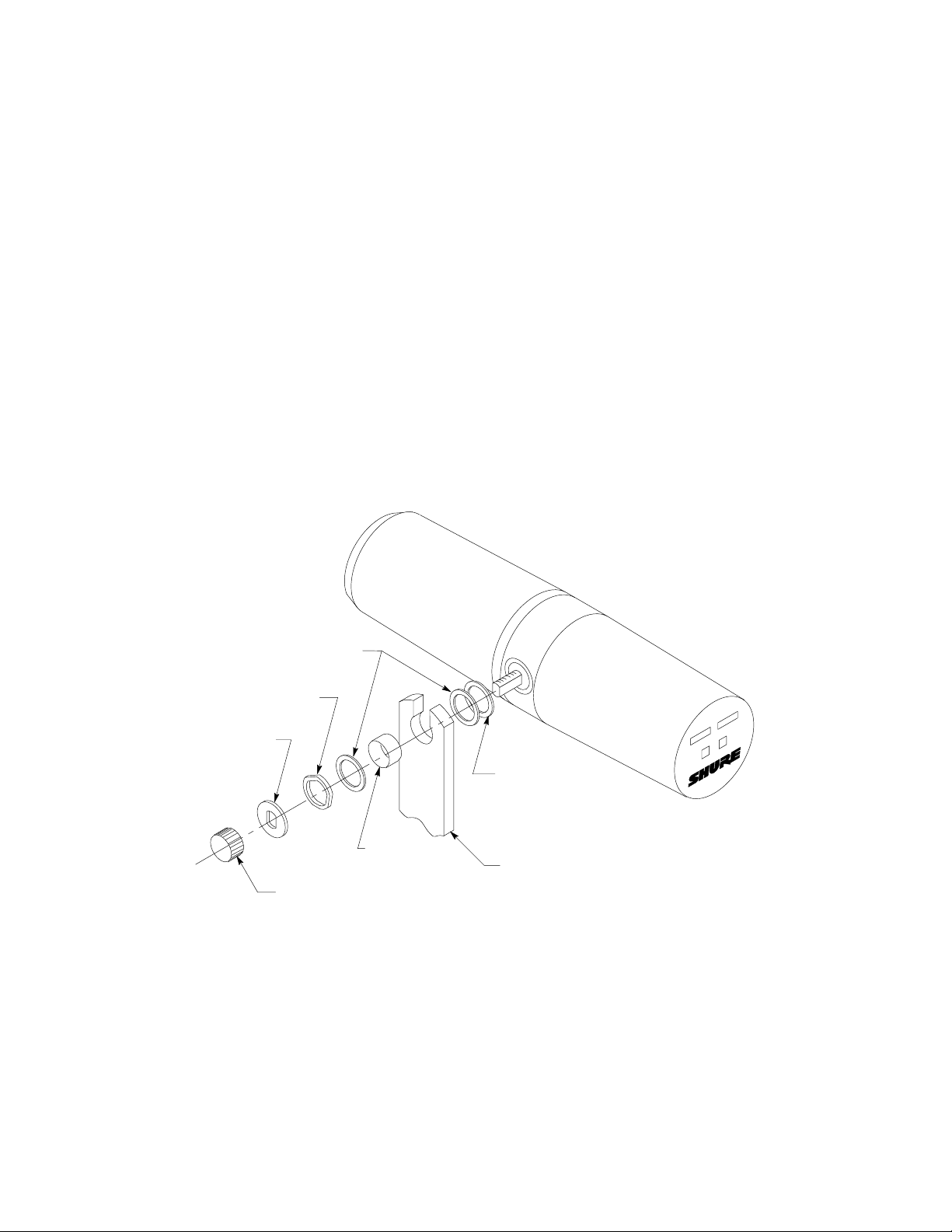
1. Remove tightening nuts on the sides (see Figure 7).
2. Remove the fitted washers, the lock washers, the outer
washers, and the brass sleeves.
brass
3. Slide the bracket off the microphone. Be careful not to lose
washers still on the microphone.
the
4. Invert and rotate the bracket. Slide it back onto the bolts
the brass and plastic washers still on the microphone.
over
Th
e bracket should fit so the XLR connector faces the rear
the microphone, and the Shure logo on the back of the
of
microphone
is right-side up.
5. Replace the brass sleeves. Be sure they are seated proper-
ly
within the inner washers.
6. Replace the outer brass washers, the lock washers and the
washers.
fitted
7. Replace the tightening nuts and tighten the microphone at
the desired angle.
NOTE: If
in
position, one or both of the brass sleeves may not be
properly
the tightening nuts do not hold the microphone
seated within all the washers.
inch from the base of
VELCRO STRIP
©2005, Shure Incorporated
27B3128 (Rev. 2)
Printed in U.S.A
.
Page 2
RIGHT SIDE VIEW
REAR VIEW
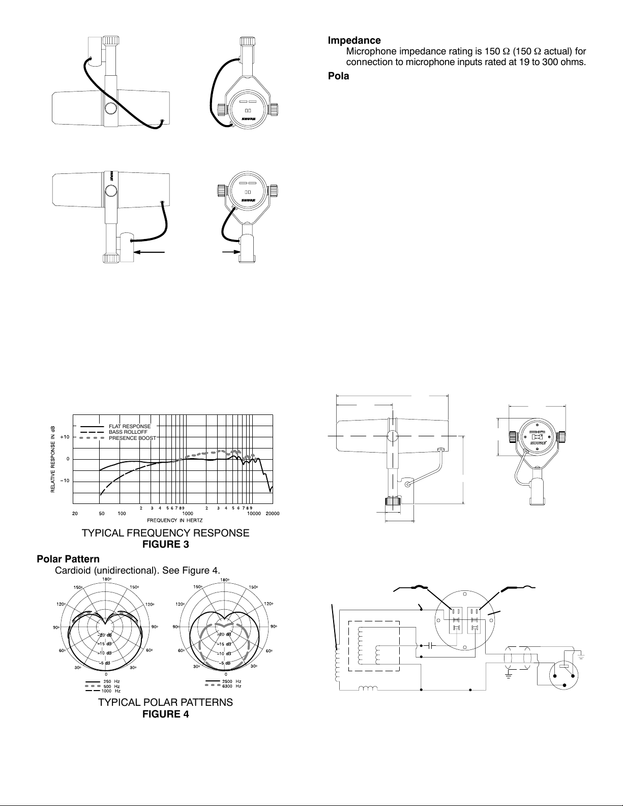
BOOM MOUNTING CONFIGURATION
FIGURE 1
XLR CONNECTOR
RIGHT SIDE VIEW REAR VIEW
MICROPHONE STAND MOUNTING CONFIGURATION
FIGURE 2
RESPONSE SELECTOR SWITCH COVER
Use the supplied cover plate to prevent accidental change
of response setting.
SPECIFICATIONS
Type
Dynamic
Frequency Response
50 to 20,000 Hz (see Figure 3)
Impedance
Microphone impedance rating is 150 Ω (150 Ω actual) for
connection to microphone inputs rated at 19 to 300 ohms.
Polarity
Positive pressure on diaphragm produces positive voltage on pin 2 relative to pin 3.
Output Level (at 1,000 Hz)
Open Circuit Voltage* – 59.0 dB (1.12 mV)
. . . . . . . . . .
*0 dB = 1 volt per Pascal
Electromagnetic Hum Sensitivity
(Typical, Equivalent SPL/milliOersted)
60 Hz: 11 dB
500 Hz: 24 dB
1 kHz: 33 dB
Switches
Bass rolloff and mid-range emphasis: Slotted response
selector switches. See Figure 3 for bass rolloff and
mid-range emphasis (presence boost) response.
Cartridge Shock Mount
Internal air-suspension shock and vibration isolator.
Microphone Connector
Three-pin professional audio (XLR)
Swivel Assembly
Integrated, captive nut for ease of attachment to stand, fits
5
/8in.–27 thread.
Case
Dark gray enamel aluminum and steel case with dark gray
foam windscreen.
Dimensions
See Figure 5.
95 mm
(3.75 in.)
189.7 mm
(7.469 in.)
96 mm
(3.775 in.)
FLAT RESPONSE
BASS ROLLOFF
PRESENCE BOOST
TYPICAL FREQUENCY RESPONSE
FIGURE 3
Polar Pattern
Cardioid (unidirectional). See Figure 4.
TYPICAL POLAR PATTERNS
FIGURE 4
25.4 mm
(1.0 in.)
OVERALL DIMENSIONS
Net Weight
765.4 grams (1 lb, 11 oz)
PRESENCE BOOST SWITCH
VOICE
COIL
240 mH
HUM BUCKING COIL
11 mH
CODED
TERMINAL
INTERNAL CONNECTIONS
48 mm
(1.890 in.)
BLACK
.22 µF
x 35 V
117 mm
(4.594 in.)
FIGURE 5
YELLOW
GREEN
WHITE
FIGURE 6
63.5 mm
(2.500 in.)
BASS ROLLOFF SWITCH
SWITCH PLATE
(VIEWED FROM
TERMINAL SIDE)
SHIELD
BLACK
CLEAR
CASE
GROUND
GREEN
2
1
3
2
Page 3
Certification
Eligible to bear CE marking. Conforms to European EMC
Directive 89/336/EEC. Meets applicable tests and performance criteria in European Standard EN 55103 (1996)
parts 1 and 2, for residential (E1) and light industrial (E2)
environments.
FURNISHED ACCESSORY
Switch Cover Plate RPM602
. . . . . . . . . . . . . . . . . . . . . . . . . .
Close-Talk Windscreen A7WS. . . . . . . . . . . . . . . . . . . . . . . . . .
OPTIONAL ACCESSORIES
Desk Stand S37A, S39A
. . . . . . . . . . . . . . . . . . . . . . . . . . . . .
Cable and Plug Assembly (7.6m – 25 ft) C25F. . . . . . . . . . . .
REPLACEMENT PART
Cartridge RPM106. . . . . . . . . . . . . . . . . . . . . . . . . . . . . . . . . . . .
Windscreen RK345. . . . . . . . . . . . . . . . . . . . . . . . . . . . . . . . . .
Nut/Washers RPM604. . . . . . . . . . . . . . . . . . . . . . . . . . . . . . . . .
ARCHITECTS’ SPECIFICATIONS
The microphone shall be a moving coil (dynamic) type with
a frequency response of 50 to 20,000 Hz. The unit shall have
a cardioid polar characteristic. The cancellation at the sides
shall be approximately 6 dB and the cancellation at the rear
shall be 15 to 20 dB. The microphone shall be low impedance
with a rated impedance of 150 ohms for connection to
microphone inputs rated at 19 to 300 ohms. The microphone
output shall be –57.0 dB where 0 dB = 1 milliwatt per Pascal.
The microphone shall have two switches for controlling the
frequency response. The first switch is a Bass Rolloff selector
switch. One position of this switch provides a flat low frequency
response and the second position provides a gradual low
frequency rolloff. The second switch is the Mid-Range
Emphasis (presence boost) switch. One position of this switch
provides a flat mid-range frequency response and the second
position raises the level of the mid-range frequency response.
The microphone shall be equipped with an integral swivel
assembly suitable for mounting on a stand with a 5/8 in-27
thread.
The overall dimensions shall be 189.7 mm (7.469 in.) in
length, 148 mm (5.812 in.) in height, and 96 mm (3.775 in.) in
width. The weight of the microphone shall be 765.4 g (1 lb.,
11 oz.)
The microphone shall be the Shure Model SM7B or
equivalent.
FITTED
WASHER
BRASS
WASHERS
LOCK
WASHER
PLASTIC
WASHER
BRASS
SLEEVE
TIGHTENING
NUT
MOUNTING
BRACKET
MOUNTING ASSEMBLY – EXPLODED VIEW
FIGURE 7
3
Page 4
GUIDE DE L’UTILISATEUR DU MODÈLE SM7B
GÉNÉRALITÉS
Le microphone électrodynamique SM7B a une réponse en
fréquence uniforme et plate sur une gamme étendue, convenant à la musique et la parole dans toutes les applications audio professionnelles. Il est doté d’un excellent blindage contre
le ronflement électromagnétique généré par les moniteurs
d’ordinateur, néons et autres appareils électriques. Le SM7B
est une mise à jour de modèles plus anciens offrant un support
amélioré pour une meilleure stabilité. En plus de sa bonnette
anti–vent standard, il comprend la bonnette anti–vent A7WS
pour les applications de proximité.
Avantages
• Réponse en fréquence plate et sur une gamme étendue
pour une reproduction pure et naturelle de la musique et de
la parole
• Atténuation de basse et accentuation en milieu de gamme
(amplification de présence) réglables par interrupteur
• Blindé contre les parasites à large bande émis par les
moniteurs d’ordinateur et autres appareils électriques—excellent rejet du ronflement électromagnétique
• Isolement à amortisseur pneumatique interne qui élimine
virtuellement la transmission des bruits mécaniques
• Bonnette anti–vent A7WS incluse pour la narration ou le
captage vocal rapproché
• Support articulé à adaptateur de pied intégré pour un
montage facile et un placement précis du microphone
• Courbe de directivité cardioïde uniforme selon la fréquence
et symétrique par rapport à l’axe pour fournir un rejet
maximum et une coloration minimum des sons hors axe
• Construction robuste et excellente protection de la capsule
pour une fiabilité à toute épreuve
BONNETTE ANTI–VENT
Utiliser la bonnette anti–vent standard pour les applications
vocales et instrumentales standard. Utiliser la bonnette anti–
vent A7WS fournie pour les applications de proximité, telles
que les voix off ou les annonces radio, car elle offre une protection maximum contre les bruits de respiration et les explosives
et crée un son plus chaud et plus intime.
Pour installer la bonnette A7WS, procéder comme suit :
1. Pour éviter de déchirer la bonnette anti–vent quand on
l’enlève, la saisir par l’anneau en plastique et la base et
la retirer en tirant doucement avec un mouvement de torsion.
2. Le cas échéant, coller les bandes Velcro fournies autour
de la grille du microphone, à environ 25 mm de la base de
la grille (comme illustré ci–dessus) pour maintenir la bonnette anti–vent neuve en place.
BANDE VELCRO
3. Pour installer la bonnette anti–vent A7WS, l’étirer sur les
bandes Velcro puis la serrer à la base pour qu’elle adhère
au Velcro. Aucune bande Velcro n’est nécessaire à l’intérieur de la bonnette car celle–ci adhère au Velcro. Pour
l’enlever, saisir la base de la bonnette anti–vent et la tirer
avec un mouvement de torsion.
APPLICATIONS
Les performances exceptionnelles et les caractéristiques
uniques du SM7B en font le choix idéal pour des applications
telles que :
• Studio d’enregistrement—Instruments et voix
• Enregistrement en extérieur
• Sonorisation de film et de télévision
• Causeries et service des informations de télévision
• Annonces radio et réalisation
• Narration
PROTECTION DU SÉLECTEUR DE RÉPONSE
Utiliser la plaque de protection fournie pour empêcher le
changement accidentel du réglage de la réponse.
4
Page 5
INSTRUCTIONS D’INSTALLATION
Le SM7B peut être monté sur un pied de microphone ou
pendu à une girafe. Il est expédié dans la configuration de
montage sur girafe (voir figure 1). Pour mettre le SM7B en
configuration de montage sur pied (voir figure 2), procéder
comme suit :
1. Enlever les écrous de serrage des côtés (voir figure 3).
2. Retirer les rondelles ajustées, les rondelles–frein, les ron-
delles en laiton extérieures et les manchons en laiton.
3. Sortir le support du microphone en le faisant glisser. Faire
attention à ne pas perdre les rondelles restant sur le microphone.
4. Retourner et tourner le support. Le remettre sur les boulons
par–dessus les rondelles en laiton et en plastique encore
sur le microphone. Le support doit s’ajuster de manière à
ce que le connecteur type XLR soit orienté vers l’arrière du
microphone et que le logo Shure situé au dos du microphone soit à l’endroit.
5. Remettre les manchons en laiton en place. Veiller à ce qu’ils
soient correctement logés à l’intérieur des rondelles intérieures.
6. Remettre en place les rondelles en laiton extérieures, les
rondelles–frein et les rondelles ajustées.
7. Remettre les écrous de serrage et serrer le microphone à
l’angle souhaité.
REMARQUE : Si le serrage des écrous ne maintient pas
le microphone en place, il est possible qu’un ou les deux
manchons en laiton ne soient pas correctement logés à
l’intérieur des rondelles.
CONFIGURATION DE MONTAGE SUR GIRAFE
FIGURE 1
CONFIGURATION DE MONTAGE SUR PIED
FIGURE 2
RONDELLES EN
LAITON
RONDELLE–FREIN
RONDELLE
AJUSTÉE
ÉCROU DE
SERRAGE
RONDELLE
EN
PLASTIQUE
MANCHON
EN LAITON
BLOC DE
MONTAGE
MONTURE – VUE ÉCLATÉE
FIGURE 3
5
Page 6

Á
Á
Á
Á
Á
Á
CARACTÉRISTIQUES
Type
Électrodynamique
Réponse en fréquence
50 à 20.000 Hz (voir figure 4)
Courbe de directivité
Configuration cardioïde (unidirectionnelle). Voir figure 5.
Impédance
L’impédance nominale du microphone est de 150 Ω (150 Ω
réelle) pour la connexion aux entrées de microphone à 19
à 300 ohms.
Polarité
Une pression positive sur le diaphragme produit une tension
positive sur la broche 2 par rapport à la broche 3.
Niveau de sortie (à 1 000 Hz)
Tension en circuit ouvert* – 59,0 dB (1,12 mV)
. . . . . . . . .
*0 dB = 1 V par Pascal
Sensibilité au ronflement électromagnétique
(typique, équivalent NPA/milliOersted)
60 Hz : 11 dB
500 Hz : 24 dB
1 kHz : 33 dB
Interrupteurs
Atténuation de basse et accentuation en milieu de gamme :
Sélecteurs de réponse en fente. Voir à la figure 4 la réponse
de l’atténuation de basse et l’accentuation en milieu de
gamme (amplification de présence).
Monture silentbloc de la capsule
Amortisseur pneumatique interne et isolateur de vibrations.
Connecteur du microphone
Audio professionnel à trois broches (XLR)
Ensemble articulé
Intégré, à écrou captif pour fixation facile au pied, filetage
5
/8po–27.
Corps
Corps en acier et en aluminium vernis gris foncé avec
bonnette anti–vent en mousse gris foncé.
Dimensions
Voir figure 6.
Poids net
765,4 grammes (1 lb, 11 oz)
Homologation
Autorisé à porter la marque CE. Conforme à la directive
CEM européenne 89/336/CEE. Conforme aux critères
applicables de test et de performances de la norme
européenne EN 55103 (1996) parties 1 et 2 pour les
environnements résidentiels (E1) et d’industrie légère (E2).
ACCESSOIRE FOURNI
Plaque de protection de sélecteur RPM602
. . . . . . . . . . . . . .
Bonnette anti–vent de proximité A7WS. . . . . . . . . . . . . . . . . .
ACCESSOIRES EN OPTION
Socle de pupitre S37A, S39A
. . . . . . . . . . . . . . . . . . . . . . . . .
Câble et fiche (7,6 m – 25 pi) C25F. . . . . . . . . . . . . . . . . . . . .
PIÈCES DE RECHANGE
Capsule RPM106. . . . . . . . . . . . . . . . . . . . . . . . . . . . . . . . . . . . .
Bonnette anti–vent RK345. . . . . . . . . . . . . . . . . . . . . . . . . . . .
Écrou/rondelles RPM604. . . . . . . . . . . . . . . . . . . . . . . . . . . . . .
RÉPONSE EN FRÉQUENCE TYPIQUE
COURBES DE DIRECTIVITÉ TYPIQUES
95 mm
(3.75 in.)
25.4 mm
(1.0 in.)
DIMENSIONS HORS TOUT
COMMUTATEUR D’AMPLIFICATION DE PRÉSENCE
BOBINE
MOBILE
240 mH
BOBINE DE COMPENSATION
DU RONFLEMENT
11 mH
BORNE
CODIFIÉE
CONNEXIONS INTERNES
6
FLAT RESPONSE
BASS ROLLOFF
PRESENCE BOOST
FIGURE 4
FIGURE 5
189.7 mm
(7.469 in.)
48 mm
(1.890 in.)
FIGURE 6
NOIR
.22 µF
x 35 V
JAUNE
VERT
BLANC
FIGURE 7
96 mm
(3.775 in.)
63.5 mm
(2.500 in.)
117 mm
(4.594 in.)
COMMUTATEUR D’ATTÉNUATION DES BASSES
PLAQUE DE COMMUTATEUR (VUE DU
CÔTÉ DE LA BORNE)
BLINDAGE
NOIR
TRANSLUCIDE
MASSE DU
CORPS
VERT
2
1
3
Page 7

BEDIENUNGSANLEITUNG FÜR MODELL SM7B
ALLGEMEINES
Das Modell SM7B ist ein dynamisches Mikrofon mit einem
ausgeglichenen, ebenen Frequenzgang und einem breiten
Frequenzbereich, das sich für Musik– und Sprachabnahme
bei allen Profi–Audioanwendungen eignet. Es weist eine hervorragende Abschirmung gegen elektromagnetischen
Brumm auf, der durch Computermonitore, Neonleuchten und
andere elektrische Geräte erzeugt wird. Das SM7B unterscheidet sich von Vormodellen durch eine verbesserte Halterungskonstruktion, die größere Stabilität bietet. Neben dem
standardmäßigen Windschutz ist auch der Windschutz A7WS
für Nahbesprechungsanwendungen im Lieferumfang enthalten.
Merkmale
• Ebener Frequenzgang mit breitem Frequenzbereich für
reine und natürliche Wiedergabe von Musik und Sprache
• Umschaltbare Einstellungen für Bassdämpfung und Mitte-
nanhebung (Präsenzverstärkung)
• Abschirmung gegen Breitbandstörungen durch Computer-
monitore und andere elektrische Geräte—hervorragende
Unterdrückung von elektromagnetischem Brumm
• Interne „luftgefederte“ Schwingungsdämpfung beseitigt
praktisch jegliche mechanische Geräuschübertragung
• Windschutz A7WS für Nahabnahme von Sängern oder
Sprechern
• Schwenkhalterung mit integriertem Mikrofonstativhalter zur
einfachen Montage und präzisen Mikrofonplatzierung
• Nierenrichtcharakteristik mit gleichförmigem Frequenz-
gang und Achsensymmetrie bietet maximale Unterdrükkung und minimale Verfärbung außeraxialer Klänge
• Robuste Ausführung und ausgezeichneter Kapselschutz
für hervorragende Zuverlässigkeit
WINDSCHUTZ
Der standardmäßige Windschutz sollte für allgemeine
Stimm– und Instrumentalanwendungen verwendet werden.
Der mitgelieferte Windschutz A7WS eignet sich am besten für
Nahabnahmeanwendungen, wie z.B. Sprachaufnahmen oder
Radiosprecher, da er maximalen Schutz vor explosiven Atemgeräuschen bietet und einen wärmeren, sympathischeren
Klang erzeugt.
Zur Anbringung des A7WS folgende Schritte ausführen:
1. Um zu vermeiden, dass der Windschutz beim Abnehmen
reißt, am Kunststoffring und Sockel anfassen und durch
behutsames Ziehen und Drehen abnehmen.
2. Falls gewünscht, die mitgelieferten Velcro–Streifen um
den Mikrofongrill herum ankleben, ungefähr 2–3 cm vom
Grillsockel entfernt (siehe Abbildung), um den neuen
Windschutz an Ort und Stelle zu halten.
VELCRO–STREIFEN
3. Den Windschutz A7WS anbringen, indem er über die Velcro–Streifen gespannt wird und dann der Sockel des
Windschutzes zusammengedrückt wird, damit er an den
Velcro–Streifen haftet. Innerhalb des Windschutzes ist
kein Velcro nötig, da er selbst am Velcro haftet. Zum Abnehmen den Sockel des Windschutzes ergreifen und mit
drehenden Bewegungen abziehen.
ANWENDUNGEN
Durch seine außergewöhnliche Leistung und die einzigartigen Eigenschaften stellt das SM7B das Mikrofon der Wahl für
folgende Anwendungszwecke dar:
• Aufnahmestudio—Instrumental– und Gesangsaufnahmen
• Aufnahmen vor Ort
• Film– und Fernsehmusikaufnahmen
• Fernseh–Talk–Shows und Nachrichtensprecher
• Radiosprecher und –produktion
• Sprechtextaufnahmen
ABDECKUNG DES FREQUENZGANGWAHLSCHALTERS
Durch Verwendung der mitgelieferten Abdeckplatte lässt
sich versehentliches Verstellen der Frequenzgangeinstellung
verhindern.
7
Page 8

MONTAGEANWEISUNGEN
Das SM7B kann an einem Mikrofonstativ befestigt oder von
einem Galgen gehängt werden. Es wird in der Konfiguration
zur Galgenmontage versandt (siehe Abbildung 1). Zur Einrichtung des SM7B für die Konfiguration zur Mikrofonstativmontage (siehe Abbildung 2) wie folgt vorgehen:
1. Die Befestigungsmuttern an den Seiten abschrauben (sie-
he Abbildung 3).
2. Die Passscheiben, die Sicherungsscheiben, die äußeren
Messingscheiben und die Messinghülsen entfernen.
3. Die Halterung vom Mikrofon abziehen. Darauf achten, dass
die Scheiben, die sich noch am Mikrofon befinden, nicht
verloren gehen.
4. Die Halterung umkehren und drehen. Auf die Schrauben
über den Messing– und Kunststoffscheiben, die sich noch
am Mikrofon befinden, zurückschieben. Die Halterung sollte so passen, dass der XLR–Stecker zur Mikrofonrückseite
weist und das Shure–Logo auf der Mikrofonrückseite nicht
auf dem Kopf steht.
5. Die Messinghülsen wieder anbringen. Sicherstellen, dass
sie sich richtig innerhalb der inneren Scheiben befinden.
6. Die äußeren Messingscheiben, die Sicherungsscheiben
und die Passscheiben wieder anbringen.
7. Die Befestigungsmuttern wieder einschrauben und das Mi-
krofon im gewünschten Winkel befestigen.
HINWEIS: Wenn die Befestigungsmuttern das Mikrofon
nicht sicher halten, sitzen eventuell eine oder beide der
Messinghülsen nicht richtig innerhalb von allen Scheiben.
KONFIGURATION ZUR GALGENMONTAGE
ABBILDUNG 1
KONFIGURATION ZUR MIKROFONSTATIVMONTAGE
ABBILDUNG 2
MESSINGSCHEIBEN
SICHERUNGSSCHEIBE
PASSSCHEIBE
KLEMMMUTTER
BEFESTIGUNGSBAUGRUPPE – EXPLOSIONSDARSTELLUNG
MESSINGHÜLSE
KUNSTSTOFFSCHEIBE
MONTAGEKLAMMER
ABBILDUNG 3
8
Page 9

Á
Á
Á
Á
Á
Á
TECHNISCHE DATEN
Typ
Dynamisch
Frequenzgang
50 bis 20.000 Hz (siehe Abbildung 4)
Richtcharakteristik
Nierencharakteristik (Richtmikrofon). Siehe Abbildung 5.
Impedanz
Die Nennimpedanz des Mikrofons beträgt 150 Ω (150 Ω
Istwert) für Anschluss an Mikrofoneingänge mit Nennimpedanzen von 19 bis 300 Ohm.
Polarität
Positiver Druck an der Membran erzeugt positive Spannung
an Pin 2 in bezug auf Pin 3.
Ausgangspegel (bei 1000 Hz)
Leerlaufspannung* –59,0 dB (1,12 mV)
. . . . . . . . . . . . . . .
*0 dB = 1 Volt je Pascal
Empfindlichkeit für elektromagnetischen Brumm
(typisch, äquivalenter Schalldruckpegel/Millioersted)
60 Hz: 11 dB
500 Hz: 24 dB
1 kHz: 33 dB
Schalter
Bassdämpfung und Mittenanhebung: Frequenzgangauswahl–Schlitzschalter. Siehe Abbildung 7 für Bassdämpfungs– und Mittenanhebungs– (Präsenzverstärkungs)–Frequenzgang.
Kapselerschütterungsabsorber
Interner luftgefederter Schwingungs– und
Vibrationsdämpfer.
Mikrofonstecker
Dreipoliger Profi–Audiostecker (XLR)
Schwenkbaugruppe
Integriert; mit unverlierbarer Mutter zum einfachen Anbrin-
5
gen an Stativ; für
/8Zoll–27–Gewinde geeignet.
Gehäuse
Dunkelgraues Email–Aluminium– und Stahlgehäuse mit
dunkelgrauem Schaumstoff–Windschutz.
Abmessungen
Siehe Abbildung 6.
Nettogewicht
765,4 g
ZERTIFIZIERUNG
Zur CE–Kennzeichnung berechtigt. Entspricht der europäischen Richtlinie zur elektromagnetischen Verträglichkeit
89/336/EWG. Erfüllt die Prüfungs– und Leistungskriterien
der europäischen Norm EN 55103 (1996) Teile 1 und 2, für
Wohngebiete (E1) und Gewerbegebiete (E2).
MITGELIEFERTES ZUBEHÖR
Schalterabdeckplatte RPM602
. . . . . . . . . . . . . . . . . . . . . . . .
Nahbesprechungswindschutz A7WS. . . . . . . . . . . . . . . . . . . .
SONDERZUBEHÖR
Tischstativ S37A, S39A
. . . . . . . . . . . . . . . . . . . . . . . . . . . . . .
Kabel mit Stecker (7,6 m) C25F. . . . . . . . . . . . . . . . . . . . . . . .
ERSATZTEILE
Kapsel RPM106. . . . . . . . . . . . . . . . . . . . . . . . . . . . . . . . . . . . . .
Windschutz RK345. . . . . . . . . . . . . . . . . . . . . . . . . . . . . . . . . .
Mutter/Scheiben RPM604. . . . . . . . . . . . . . . . . . . . . . . . . . . . .
9
RELATIVER FREQUENZGANG IN dB
TYPISCHE RICHTCHARAKTERISTIKEN
95 mm
25.4 mm
PRÄSENZANHEBUNGSSCHALTER
SCHWINGSPULE
240 mH
ENTBRUMMSPULE
EBENER FREQUENZGANG
BASS–ROLLOFF
PRÄSENZANHEBUNG
FREQUENZ IN Hz
TYPISCHER FREQUENZGANG
ABBILDUNG 4
ABBILDUNG 5
189.7 mm
63.5 mm
117 mm
48 mm
GESAMTABMESSUNGEN
ABBILDUNG 6
BASS–ROLLOFF–SCHALTER
CODIERTER AN-
11 mH
SCHLUSS
SCHWARZ
.22 µF
x 35 V
GELB
GRÜN
LICHTDURCHLÄSSIG
WEISS
SCHALTERPLATTE (ANSICHT
VON ANSCHLUSSEITE)
ABSCHIRMUNG
SCHWARZ
GEHÄUSEERDE
INTERNE ANSCHLÜSSE
ABBILDUNG 7
96 mm
VERT
2
1
3
Page 10

GUÍA DEL USUARIO DE MODELO SM7B
GENERALIDADES
El micrófono dinámico modelo SM7B tiene una respuesta de
frecuencia uniforme, plana y amplia que es adecuada para la
reproducción de música y voz en todas las situaciones de presentaciones profesionales. Cuenta con un blindaje excelente
contra el zumbido electromagnético generado por pantallas
de computadora, luces de neón y otros dispositivos eléctricos.
El SM7B tiene mejoras en comparación con modelos anteriores y cuenta con una escuadra de diseño mejorado que ofrece
mayor estabilidad. Además de su paravientos estándar, incluye el paravientos A7WS para las situaciones de captación de
voz a distancias cortas.
Características
• Una respuesta de frecuencia plana y amplia para brindar
una reproducción nítida y natural de tanto música como voz
• Interruptores de atenuación progresiva de frecuencias
bajas y de amplificación de banda media (aumento de
presencia)
• Blindaje contra interferencias de banda ancha generadas
por pantallas de computadoras y otros dispositivos eléctricos — nivel excelente de rechazo de zumbidos electromagnéticos
• El amortiguador interno con “suspensión neumática” prácti-
camente elimina la transmisión de ruidos de origen
mecánico
• Incluye el paravientos A7WS para captar voces a distan-
cias muy cortas
• La escuadra giratoria con adaptador incorporado para
pedestal facilita el montaje del micrófono y permite ajustar
su posición de forma precisa
• Su patrón polar de captación de cardioide, uniforme
respecto a la frecuencia y simétrico respecto a su eje,
proporciona el rechazo máximo y la coloración mínima de
los sonidos originados fuera de su eje principal de
captación
• Fabricación resistente y excelente protección de la cápsula
para brindar una confiabilidad sobresaliente.
PARAVIENTOS
Utilice el paravientos normal para las situaciones generales
de captación de voz e instrumentos. Utilice el paravientos
A7WS incluido para situaciones de captación de voz a distancias cortas, tal como las grabaciones en estudio y locución radial, puesto que ofrece la protección máxima contra los ruidos
del aliento y crea un sonido más cálido e íntimo.
Para instalar el A7WS, utilice las instrucciones siguientes:
1. Para evitar romper el paravientos al quitarlo, sujételo por
el anillo de plástico y por su base y quítelo tirando y torciéndolo suavemente.
2. Si así se desea, coloque las tiras de Velcro provistas alrededor de la malla del micrófono, a aproximadamente dos
centímetros de la base de la malla (como se ilustra arriba)
para sujetar el paravientos nuevo en su lugar.
TIRA DE VELCRO
3. Instale el paravientos A7WS estirándolo sobre las tiras de
Velcro y luego comprimiendo su base para adherirla al
Velcro. No se necesita una tira de Velcro dentro del paravientos, puesto que éste se adhiere por sí solo al material
Velcro. Para quitarlo, sujete la base del paravientos y tire
de la misma mientras se la retuerce.
CUBIERTA DE INTERRUPTORES SELECTORES DE
RESPUESTA
Utilice la cubierta incluida para evitar la modificación inad-
vertida del ajuste de respuesta.
APLICACIONES
El rendimiento excepcional y las características únicas del
SM7B lo convierten en la alternativa sobresaliente para aplicaciones tales como:
• Estudios de grabación — Música instrumental y cantada
• Grabación en sitio
• Grabación de pistas para películas y programas de
televisión
• Entrevistas y noticieros por televisión
• Locución y producción de radio
• Narraciones
10
Page 11

INSTRUCCIONES DE MONTAJE
El SM7B puede montarse en un pedestal de micrófonos estándar, o en un pedestal de extensión. Se despacha en la configuración de montaje en pedestal de extensión (vea la Figura 1). Para configurar el SM7B para montaje en pedestal de
micrófonos (vea la Figura 2), efectúe el procedimiento siguiente:
1. Quite las tuercas de fijación de los costados
(vea la Figura 3).
2. Quite las arandelas moldeadas, las arandelas de seguri-
dad, las arandelas exteriores de latón y los manguitos de
latón.
3. Deslice la escuadra para quitarla del micrófono. Evite per-
der las arandelas que todavía están en el micrófono.
4. Invierta y gire la escuadra. Deslícela nuevamente sobre los
pernos, sobre las arandelas de latón y de plástico que permanecieron con el micrófono. La escuadra debe quedar
orientada de modo que el conector XLR quede hacia la parte trasera del micrófono y el logotipo Shure de la parte posterior del micrófono esté en posición derecha.
5. Vuelva a colocar los manguitos de latón. Asegúrese que
queden debidamente asentados en las arandelas interiores.
6. Vuelva a colocar las arandelas exteriores de latón, las aran-
delas de seguridad y las arandelas moldeadas.
7. Vuelva a colocar las tuercas de fijación y apriete el micrófo-
no al ángulo deseado.
NOTA: Si las tuercas de fijación no sujetan al micrófono
en posición, uno o los dos manguitos de latón podrían no
estar debidamente asentados en las arandelas.
CONFIGURACION PARA MONTAJE EN BRAZO
FIGURA 1
CONFIGURACION PARA MONTAJE
EN PEDESTAL DE MICROFONO
FIGURA 2
ARANDELAS DE LATON
ARANDELA DE SEGURIDAD
ARANDELA MOLDEADA
MANGUITO
DE LATON
TUERCA DE APRIETE
CONJUNTO DE MONTAJE – DESPIECE
ARANDELA
DE PLASTICO
ESCUADRA DE
MONTAJE
FIGURA 3
11
Page 12

Á
Á
Á
Á
Á
ESPECIFICACIONES
Tipo
Dinámico
Respuesta de frecuencia
50 a 20.000 Hz (vea la Figura 4)
Patrón polar
Cardioide (unidireccional). Vea la Figura 5.
Impedancia
La impedancia nominal del micrófono es de 150 Ω (150 Ω
real) para conectarlo a entradas de micrófono con impedancias nominales de 19 a 300 ohmios.
Polaridad
Una presión positiva sobre el diafragma produce un voltaje
positivo en la clavija 2 con respecto a la clavija 3.
Nivel de salida (a 1000 Hz)
Voltaje en circuito abierto* – 59,0 dB (1,12 mV)
. . . . . . . .
*0 dB = 1 voltio por Pascal
Sensibilidad a zumbidos electromagnéticos
(Típica, SPL equivalente/mOe)
60 Hz: 11 dB
500 Hz: 24 dB
1 kHz: 33 dB
Interruptores
Atenuación de bajos y amplificación de banda media:
Interruptores selectores de respuesta. Vea la Figura 7 para
las respuestas de atenuación de bajos y de amplificación de
banda media (presencia).
Soporte amortiguado de la cápsula
Suspensión neumática interna y amortiguador de vibraciones.
Conector del micrófono
Conector de audio de tres clavijas profesional (tipo XLR)
Conjunto giratorio
Tuerca prisionera incorporada para facilitar el montaje en un
5
pedestal, acepta roscas
/8pulg–27.
Caja
Caja de aluminio y acero con acabado gris oscuro y
paravientos de espuma gris oscuro.
Dimensiones
Vea la Figura 6.
Peso neto
765,4 g (1 lb, 11 oz)
CERTIFICACIONES
Califica para portar la marca CE. Cumple la directiva
europea 89/336/EEC de compatibilidad electromagnética.
Se ajusta a los criterios correspondientes de verificación y
funcionamiento establecidos en la norma europea EN
55103 (1996), partes 1 y 2, para zonas residenciales (E1)
y zonas de industria ligera (E2).
ACCESORIO SUMINISTRADO
Cubierta de interruptores RPM602
. . . . . . . . . . . . . . . . . . . . .
Paravientos para captación a distancia corta A7WS. . . . . . .
ACCESORIOS OPCIONALES
Pedestal de escritorio S37A, S39A
. . . . . . . . . . . . . . . . . . . . .
Conjunto de cable y enchufe (7,6 m – 25 pies) C25F. . . . . .
REPUESTOS
Cápsula RPM106. . . . . . . . . . . . . . . . . . . . . . . . . . . . . . . . . . . . .
Paravientos RK345. . . . . . . . . . . . . . . . . . . . . . . . . . . . . . . . . .
Tuerca/arandelas RPM604. . . . . . . . . . . . . . . . . . . . . . . . . . . . .
12
RESPUESTA PLANA
ATENUACION PROGRESIVA DE BAJOS
AMPLIFICACION DE PRESENCIA
RESPUESTA RELATI VA EN dB
FRECUENCIA EN Hz
RESPUESTA DE FRECUENCIA TIPICA
FIGURA 4
PATRONES DE CAPTACION POLAR TIPICOS
FIGURA 5
95 mm
25.4 mm
189.7 mm
63.5 mm
117 mm
48 mm
DIMENSIONES GENERALES
FIGURA 6
INTERRUPTOR DE ATENUACION
PROGRESIVA DE BAJOS
PLACA DE INTERRUPTORES
(VISTA DE LADO DE BORNES)
NEGRO
TRANSLÚCIDO
TIERRA DE
CHASIS
BOBINA
MOVIL
BOBINA ANULADORA
DE ZUMBIDO
INTERRUPTOR DE
AMPLIFICACION DE PRESENCIA
BORNE
CODIFICADO
240 mH
11 mH
CONEXIONES INTERNAS
NEGRO
.22 µF
x 35 V
AMARILLO
VERDE
BLANCO
FIGURA 7
BLINDAJE
96 mm
VERDE
2
1
3
Page 13

GUIDA ALL’USO DEL MODELLO SM7B
DESCRIZIONE GENERALE
Il microfono dinamico SM7B presenta una risposta in frequenza ad ampia banda, piatta e regolare, adatta a tutte le applicazioni audio professionali, sia per riprese vocali che di brani musicali. È dotato di un’ottima schermatura contro il ronzio
elettromagnetico generato dai monitor, dalle lampade al neon
e da altri apparecchi elettrici. Il modello SM7B rappresenta un
passo avanti rispetto ai modelli precedenti grazie alle modifiche apportate alla staffa che lo rendono più stabile. Oltre
all’antivento standard, la dotazione comprende l’antivento
A7WS, utile quando si deve tenere il microfono vicino alla bocca.
Caratteristiche
• Risposta in frequenza ad ampia banda, piatta, per riprodur-
re con straordinaria naturalezza e chiarezza la voce di
oratori e musicisti.
• Impostazioni commutabili per l’attenuazione alle basse
frequenze e per l’enfasi alle frequenze intermedie (amplificazione di presenza).
• Schermatura contro l’interferenza a larga banda causata
dai monitor e da altri apparecchi elettrici, con un’eccellente
reiezione del ronzio elettromagnetico.
• Il sistema di smorzamento pneumatico interno elimina
praticamente la trasmissione del rumore meccanico.
• La dotazione comprende l’antivento A7WS, adatto a
cantanti e oratori che devono usare il microfono tenendolo
vicino alla bocca.
• Staffa girevole, con adattatore per sostegno integrato, per
fissare facilmente il microfono e collocarlo con precisione.
• Diagramma polare a cardioide, uniforme in frequenza e
simmetrico rispetto all’asse, per ottenere la massima
reiezione e la minima colorazione dei suoni fuori asse.
• La costruzione robusta e la protezione della capsula si
traducono in un’affidabilità straordinaria.
APPLICAZIONI
Le prestazioni e le caratteristiche uniche dell’SM7B ne fanno
la scelta quasi obbligata per numerose applicazioni:
• Registrazione in studio di strumenti e voci.
• Registrazioni esterne.
• Colonne sonore per spettacoli televisivi e film.
• Notiziari e talk show televisivi.
• Produzione e annunci radiofonici.
• Narrazione.
ANTIVENTO
L’antivento standard è adatto ad applicazioni generali strumentali e vocali, mentre il modello A7WS in dotazione va adoperato quando il microfono deve essere tenuto vicino alla bocca (per esempio in caso di commenti sonori o annunci
radiofonici) in quanto offre la massima protezione dai suoni
“esplosivi” della respirazione e crea un suono più caldo e raccolto.
Per installare l’A7WS:
1. Per evitare di lacerare l’antivento quando lo togliete, afferratelo per l’anello di plastica e per la base e staccatelo tirandolo e girandolo delicatamente.
2. Volendolo, potete fissare il nuovo antivento avvolgendo le
strisce di Velcro, in dotazione, intorno alla griglia del microfono, a circa 2,5 centimetri dalla base della griglia stessa (come illustrato nella figura precedente).
STRISCIA DI VELCRO
3. Fissate l’antivento distendendolo sopra le strisce di Velcro ed esercitando pressione sulla sua base per farlo aderire alle strisce. Non occorre usare nessuna striscia all’interno dell’antivento, in quanto esso aderisce al Velcro.
Per togliere l’antivento, afferratelo per la base e staccatelo tirandolo e girandolo delicatamente.
COPERCHIO PER IL SELETTORE DELLA RISPOSTA
Per prevenire modifiche fortuite dell’impostazione della ri-
sposta si può adoperare la piastra di copertura in dotazione.
13
Page 14

ISTRUZIONI PER IL FISSAGGIO
Il microfono SM7B può essere collocato su un sostegno apposito oppure può essere appeso a un braccio. Viene spedito
nella configurazione di fissaggio al braccio (vedi Figura 1). Per
predisporlo in modo da fissarlo a un sostegno (vedi Figura 2):
1. Togliete i dadi di serraggio sui lati (vedi Figura 3).
2. Togliete le rondelle adattate, le rondelle elastiche, le rondel-
le di ottone esterne e i manicotti di ottone.
3. Sfilate la staffa dal microfono, facendo attenzione a non
perdere le rondelle ancora inserite.
4. Capovolgete la staffa e giratela, poi inseritela sulle viti sopra
le rondelle di ottone e di plastica rimaste sul microfono. La
staffa deve adattarsi in modo che il connettore XLR sia rivolto verso la parte posteriore del microfono e che il logotipo
Shure sulla parte posteriore sia diritto.
5. Riposizionate i manicotti di ottone, verificando che siano
collocati correttamente nella sede dentro le rondelle interne.
6. Riposizionate le rondelle di ottone esterne, le rondelle ela-
stiche e le rondelle adattate.
7. Riposizionate i dadi di serraggio e fissate il microfono all’in-
clinazione desiderata.
NOTA: se i dadi di serraggio non mantengono il microfo-
no bloccato, è possibile che uno dei manicotti di ottone, o
entrambi, non siano inseriti correttamente dentro tutte le
rondelle.
CONFIGURAZIONE MONTAGGIO BRACCIO
FIGURA 1
CONFIGURAZIONE MONTAGGIO SOSTEGNO
MICROFONO
FIGURA 2
RONDELLE DI OTTONE
RONDELLE ELASTICHE
RONDELLE ADATTATE
RONDELLA DI
PLASTICA
MANICOTTO
DI OTTONE
DADO DI SERRAGGIO
STAFFA DI MONTAGGIO
COMPONENTI DI MONTAGGIO – ESPLOSO
FIGURA 3
14
Page 15

Á
Á
Á
Á
Á
DATI TECNICI
Tipo
Dinamico
Risposta in frequenza
Da 50 a 20.000 Hz (vedi Figura 4)
Diagramma polare
Cardioide (unidirezionale). Vedi Figura 5.
Impedenza
Valore nominale di 150 Ω (150 Ω effettivi) per il collegamento a ingressi microfonici con impedenza nominale compresa
tra 19 e 300 Ω.
Polarità
Una pressione sonora positiva sul diaframma produce una
tensione positiva sul piedino 2 rispetto al piedino 3.
Livello di uscita (a 1.000 Hz)
Tensione di circuito aperto* –59,0 dB (1,12 mV)
. . . . . . . .
*0 dB = 1 volt a pascal
Sensibilità al ronzio elettromagnetico
(valore tipico, livello di pressione sonora equivalente/
millioersted)
A 60 Hz: 11 dB
A 500 Hz: 24 dB
A 1 kHz: 33 dB
Interruttori
Attenuazione alle basse frequenze ed enfasi a frequenze
intermedie (amplificazione di frequenza): selettori con
risposta a intaglio. Vedi Figura 7 per la relativa risposta in
frequenza.
Supporto antivibrazione per la capsula
Sistema di smorzamento pneumatico interno e antivibrazioni.
Connettore del microfono
Tipo audio, professionale, a tre piedini (XLR)
Snodo
Integrato, con dado prigioniero per facilitare il fissaggio al
5
sostegno, si adatta a una filettatura da
/8di pollice–27.
Involucro
In acciaio e alluminio smaltato, grigio scuro, con antivento
in materiale poliuretanico grigio scuro.
Dimensioni
Vedi Figura 6.
Peso netto
765,4 grammi (1 libbra e 11 once)
OMOLOGAZIONI
Contrassegnabile con il marchio CE. Conforme alla direttiva
europea sulla compatibilità elettromagnetica 89/336/CEE.
Soddisfa i criteri di prestazione e le verifiche pertinenti della
norma europea EN 55103 (1996) parti 1 e 2 relativa ad
ambienti domestici (E1) ed industriali leggeri (E2).
ACCESSORI IN DOTAZIONE
Piastra di copertura selettore RPM602
. . . . . . . . . . . . . . . . . .
Antivento per distanza ravvicinata alla bocca A7WS. . . . . . .
ACCESSORI OPZIONALI
Sostegno da tavolo S37A, S39A
. . . . . . . . . . . . . . . . . . . . . . .
Complessivo cavo e spina (7,6m – 25 piedi) C25F. . . . . . . .
PARTI DI RICAMBIO
Capsula RPM106. . . . . . . . . . . . . . . . . . . . . . . . . . . . . . . . . . . . .
Antivento RK345. . . . . . . . . . . . . . . . . . . . . . . . . . . . . . . . . . . .
Dadi/Rondelle RPM604. . . . . . . . . . . . . . . . . . . . . . . . . . . . . . .
15
BOBINA
PER LA
VOCE
RISPOSTA PIATTA
ATTENUAZIONE ALLE BASSE FREQUENZE
AMPLIFICAZIONE DI PRESENZA
RISPOSTA RELATIVA (dB)
FREQUENZA (Hz)
RISPOSTA IN FREQUENZA TIPICA
FIGURA 4
DIAGRAMMI POLARI TIPICI
FIGURA 5
95 mm
25.4 mm
189.7 mm
117 mm
48 mm
DIMENSIONI COMPLESSIVE
FIGURA 6
INTERRUTTORE PER
AMPLIFICAZIONE DI PRESENZA
TERMINALE
CODIFICATO
NERO
240 mH
11 mH
BOBINA ANTIRONZIO
.22 µF
x 35 V
GIALLO
VERDE
BIANCO
TRANSLUCIDO
CONNESSIONI INTERNE
FIGURA 7
96 mm
63.5 mm
INTERRUTTORE PER ATTENUAZIONE
ALLE BASSE FREQUENZE
PLACCA PORTAINTERRUTTORI
(VISTA DAL LATO DEL
TERMINALE)
NERO
INVOLUCRO
SCHERMATURA
MASSA
VERDE
2
3
1
Page 16

SHURE Incorporated http://www.shure.com
United States, Canada, Latin America, Caribbean:
5800 W. Touhy Avenue, Niles, IL 60714-4608, U.S.A.
Phone: 847-600-2000 U.S. Fax: 847-600-1212 Intl Fax: 847-600-6446
Europe, Middle East, Africa:
Shure Europe GmbH, Phone: 49-7131-72140 Fax: 49-7131-721414
Asia, Pacific:
Shure Asia Limited, Phone: 852-2893-4290 Fax: 852-2893-4055
 Loading...