

Page 1
GENERAL
The Model S M7A i s a d ynamic microphone with a v ery smooth,
flat, wide-range frequency response. I t i s m eticulously d esigned
for the most exacting music and speech requirements i n professional audio applications. The cartridge has been updated from
the original S M7 w ith i mproved s hielding a gainst electromagnetic
hum generated by computer monitors, neon lights, and other
electrical devices.
Features
•
Flat, wide-range frequency response for exceptionally
clean and natural reproduction of both music and speech
•
Bass rolloff and mid-range emphasis (presence boost)
controls with graphic display of response setting (see
figure 3)
•
Improved rejection of electromagnetic hum, optimized for
shielding against broadband interference emitted by computer monitors
•
Internal “air suspension” shock isolation virtually eliminates
mechanical noise transmission
•
Highly effective pop filter eliminates need for any add-on
protection against explosive breath sounds, even for
close-up vocals or narration
•
Yoke mounting with captive stand nut for easy mounting
and dismounting provides precise control of microphone
position
•
Cardioid polar pattern, uniform with frequency and symmetrical about axis, to provide maximum rejection and minimum coloration of off-axis sound
•
Rugged construction and excellent cartridge protection for
outstanding reliability
Model SM7A User Guide
APPLICATIONS
The Model SM7A was field-designed in major recording studios and scoring stages to be the finest dynamic microphone
available for music recording and r eproduction. Exacting laboratory development programs augmented t he f ield-derived s pecifications and features to extend the advantages of the SM7A to
a wide variety of critical professional audio applications.
The exceptional p erformance a nd u nique f eatures o f t he S M7A
make it the outstanding choice for such applications as:
Recording Studio—Instrumental and Vocal
•
•
Location Recording
•
Motion Picture and Television Scoring
•
Television Talk Shows and News Desks
•
Radio Announcing and Production
•
Narration
MOUNTING INSTRUCTIONS
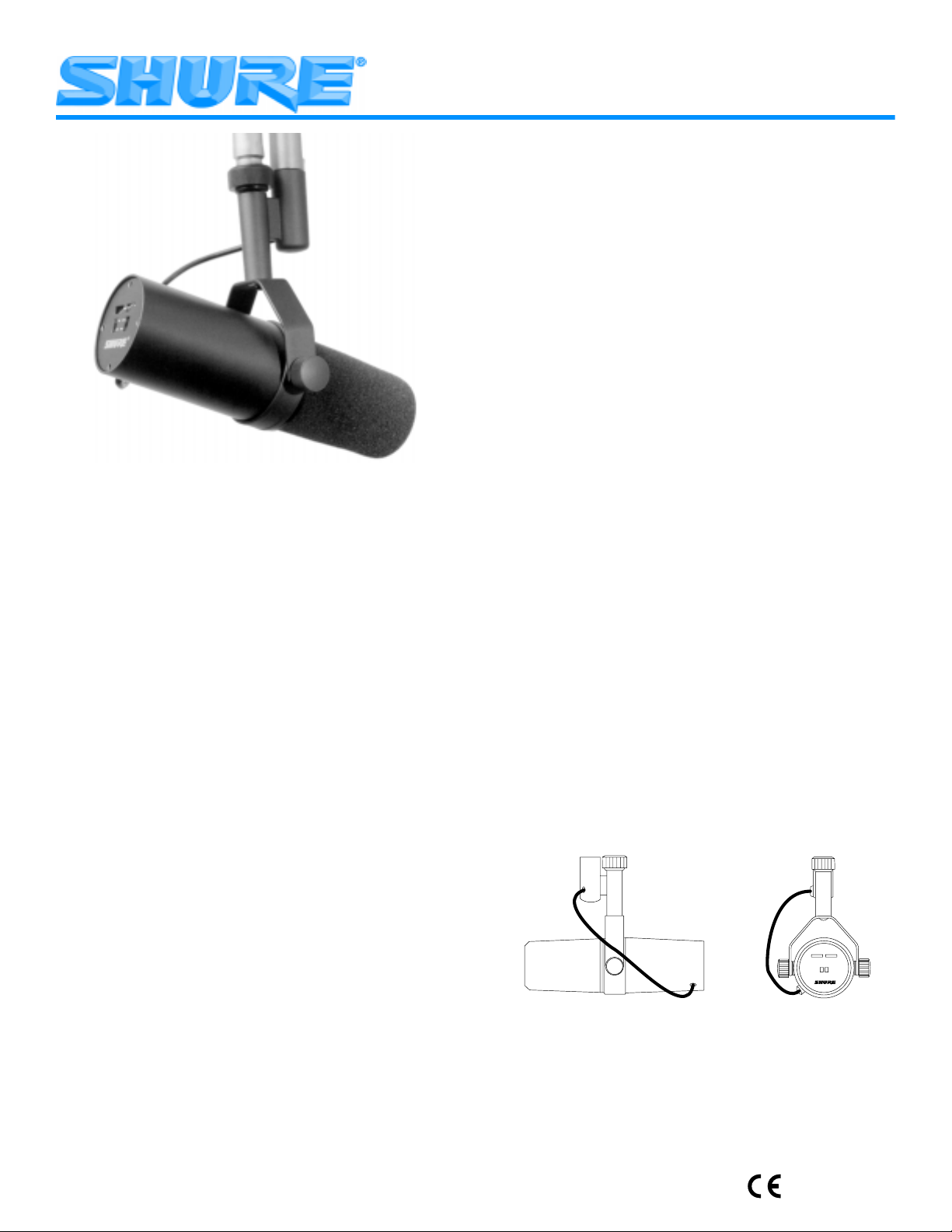
The SM7A can be mounted on a microphone stand or hung
from a boom. It is shipped in the boom mounting configuration
(see figure 1). To set up the SM7A in the microphone stand
mounting configuration (see figure 2), proceed as follows:
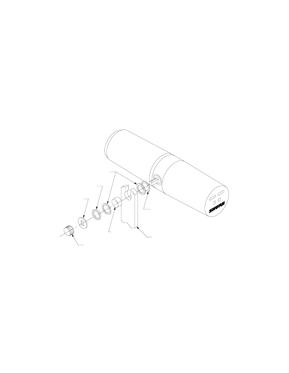
1. Remove tightening nuts on the sides (see figure 7).
2. Remove the fitted washers, the lock washers, the outer
brass washers, and the brass sleeves.
3. Slide the bracket off the microphone. Be careful not to lose
the washers still on the microphone.
4. Invert and rotate the bracket. Slide it back onto the bolts
over the brass and plastic washers still on the microphone.
The bracket should fit so the XLR connector faces the rear
of the microphone, and the Shure logo on the back of the
microphone is right-side up.
5. Replace the brass sleeves. Be sure they are seated proper-
ly within the inner washers.
6. Replace the outer brass washers, the lock washers and the
fitted washers.
7. Replace the tightening nuts and tighten the microphone at
the desired angle.
NOTE: If the tightening nuts do not hold the microphone
in position, one or both of the brass sleeves may not be
properly seated within all the washers.
RIGHT SIDE VIEW
BOOM MOUNTING CONFIGURATION
FIGURE 1
REAR VIEW
2000, Shure Incorporated
27B3076 (TF)
Printed in U.S.A.
Page 2
XLR CONNECTOR
RIGHT SIDE VIEW REAR VIEW
MICROPHONE STAND MOUNTING CONFIGURATION
FIGURE 2
SPECIFICATIONS
Type
Dynamic
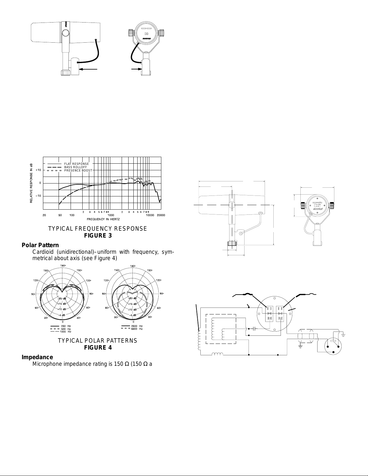
Frequency Response
50 to 20,000 Hz (see Figure 3)
FLAT RESPONSE
BASS ROLLOFF
PRESENCE BOOST
Switches
Bass rolloff and mid-range emphasis: Slotted response
selector switches. See Figure 3 for bass rolloff and
mid-range emphasis (presence boost) response. See
Figure 3 for location of switches.
Response Selector Switch Cover
Cover plate (supplied) can be used to prevent accidental
change of response setting.
Cartridge Shock Mount
Internal air-suspension shock and vibration isolator.
Microphone Connector
Three-pin professional audio connector designed to mate
with Cannon XL series, Switchcraft A3 (Q-G) series or
equivalent connector.
Swivel Assembly
Integral part of microphone with captive nut for ease of
attachment to stand, suitable for mounting on stand with
5
/8 in.–27 thread.
Case
Dark gray enamel aluminum and steel case with dark gray
foam windscreen.
Dimensions
See Figure 5.
189.7 mm
95 mm
(3.75 in.)
(7.469 in.)
96 mm
(3.775 in.)
TYPICAL FREQUENCY RESPONSE
FIGURE 3
Polar Pattern
Cardioid (unidirectional)–uniform with frequency, symmetrical about axis (see Figure 4)
TYPICAL POLAR PATTERNS
FIGURE 4
Impedance
Microphone impedance rating is 150 Ω (150 Ω actual) for
connection to microphone inputs rated at 19 to 300 ohms.
Phasing
Positive pressure on diaphragm produces positive voltage on pin 2 relative to pin 3.
Output Level (at 1,000 Hz)
Open Circuit Voltage* – 59.0 dB (1.12 mV)
. . . . . . . . . .
*0 dB = 1 volt per Pascal
Electromagnetic Hum Sensitivity
(Typical, Equivalent SPL/milliOersted)
60 Hz: 11 dB
500 Hz: 24 dB
1 kHz: 33 dB
63.5 mm
(2.500 in.)
117 mm
(4.594 in.)
25.4 mm
(1.0 in.)
48 mm
(1.890 in.)
OVERALL DIMENSIONS
FIGURE 5
Net Weight
765.4 grams (1 lb, 11 oz)
BASS ROLLOFF SWITCH
SWITCH PLATE
(VIEWED FROM
TERMINAL SIDE)
SHIELD
BLACK
CLEAR
CASE
GROUND
GREEN
2
1
3
VOICE
COIL
PRESENCE BOOST SWITCH
TERMINAL
240 mH
11 mH
HUM BUCKING COIL
CODED
BLACK
.22 µF
x 35 V
YELLOW
GREEN
WHITE
INTERNAL CONNECTIONS
FIGURE 6
Certification
Eligible to bear CE marking. Conforms to European EMC
Directive 89/336/EEC. Meets applicable tests and performance criteria in European Standard EN 55103 (1996)
parts 1 and 2, for residential (E1) and light industrial (E2)
environments.
FURNISHED ACCESSORY
Switch Cover Plate RPM602
. . . . . . . . . . . . . . . . . . . . . . . . . .
OPTIONAL ACCESSORIES
Desk Stand S37A, S39A
. . . . . . . . . . . . . . . . . . . . . . . . . . . . .
Cable and Plug Assembly (7.6m – 25 ft) C25F. . . . . . . . . . . .
2
Page 3
REPLACEMENT PART
Cartridge RPM106. . . . . . . . . . . . . . . . . . . . . . . . . . . . . . . . . . . .
Windscreen RK345. . . . . . . . . . . . . . . . . . . . . . . . . . . . . . . . . .
Nut/Washers RPM604. . . . . . . . . . . . . . . . . . . . . . . . . . . . . . . . .
ARCHITECTS’ SPECIFICATIONS
The microphone shall be a moving coil (dynamic) type with
a frequency response of 50 to 20,000 Hz. The unit shall have
a cardioid polar characteristic. The cancellation at the sides
shall be approximately 6 dB and the cancellation at the rear
shall be 15 to 2 0 dB. The microphone shall be low impedance
with a rated impedance of 150 ohms for connection to
microphone inputs rated at 19 to 300 ohms. The microphone
output shall be –57.0 dB where 0 dB = 1 milliwatt per Pascal.
The microphone shall have two switches for controlling the
frequency response. The first switch is a Bass Rolloff selector
switch. One position of this switch provides a flat low frequency
response and the second position provides a gradual low
frequency rolloff. The second switch is the Mid-Range
Emphasis (presence boost) switch. One position of this switch
provides a flat mid-range frequency response and the second
position raises the level of the mid-range frequency response.
The microphone shall be equipped with an integral swivel
assembly suitable for mounting on a stand with a 5/8 in-27
thread.
The overall dimensions shall be 189.7 mm (7.469 in.) in
length, 148 mm (5.812 in.) in height, and 96 mm (3.775 in.) in
width. The weight of the microphone shall be 765.4 g
(1 lb., 11 oz.)
The microphone shall be the Shure Model SM7A or
equivalent.
FITTED
WASHER
BRASS
WASHERS
LOCK
WASHER
PLASTIC
WASHER
BRASS
SLEEVE
TIGHTENING
NUT
MOUNTING
BRACKET
MOUNTING ASSEMBLY – EXPLODED VIEW
FIGURE 7
3
Page 4
MODÈLE SM7A
Á
Á
Á
Á
Á
Á
MICROPHONE D’ENREGISTREMENT
ÉLECTRODYNAMIQUE MONODIRECTIONNEL À
CONFIGURATION CARDIOÏDE
Le modèle SM7A est un microphone électrodynamique doté
d’une réponse en fréquence très régulière, uniforme et étendue. Il est conçu tout spécialement pour les exigences musicales et vocales des applications audio professionnelles. La
cartouche a été mise au point à partir du SM7 d’origine à l’aide
d’un blindage perfectionné contre le ronflement électromagnétique généré par les moniteurs d’ordinateurs, les éclairages au néon et les autres dispositifs électriques.
CARACTÉRISTIQUES
Type
Électrodynamique
Réponse en fréquence
50 à 20 000 Hz (voir Figure 1)
RÉPONSE PLANE
ATTÉNUATION DES BASSES
AMPLIFICATION DE PRÉSENCE
Avantages
Réponse en fréquence uniforme et étendue permettant une
reproduction nette et naturelle de la musique et de la voix
Commandes d’atténuation des basses et d’accentuation du
milieu de gamme (amplification de présence) avec affichage graphique du réglage de réponse (voir Figure 1)
Rejet amélioré du ronflement électromagnétique, optimisé
pour le blindage contre les parasites de bande large émis
par les moniteurs des ordinateurs
Isolation interne «à suspension pneumatique» contre les
bruits d’impact afin d’éliminer la transmission du bruit
mécanique
Filtre anti–bruit très efficace qui élimine la nécessité d’ajout
de module de protection contre les sons respiratoires
explosifs, même pour le captage vocal rapproché ou la
narration
Monture à berceau avec vis prisonnière du pied, facilitant
le montage/démontage et fournissant un contrôle précis de
la position du microphone
Courbe de directivité à configuration cardioïde, uniforme
avec fréquence et symétrie par rapport à l’axe, permettant
d’obtenir un rejet maximum et une coloration minimum du
son hors axe
Fabrication résistante et excellente protection de la cartouche permettant une fiabilité inégalée
APPLICATIONS
Conçu dans les studios d’enregistrement et plateaux de sonorisation importants, le modèle SM7A est le microphone
électrodynamique parfaitement adapté à l’enregistrement et à
la reproduction de musique. Des programmes rigoureux de
développement en laboratoire ont augmenté les spécifications et les fonctions conçues à partir de l’usage pratique afin
d’étendre les avantages du SM7A à un large éventail d’applications audio professionnelles importantes.
Les performances exceptionnelles et les fonctions uniques
du SM7A en font le choix idéal pour les applications telles que :
Studio d’enregistrement – Instrumental et vocal
Enregistrement en extérieur
Sonorisation de cinéma et de télévision
Causeries télévisées et salles de rédaction
Messages et production radio
Narration
RÉPONSE RELATIVE EN dB
FRÉQUENCE HERTZIENNE
RÉPONSE EN FRÉQUENCE TYPIQUE
FIGURE 1
Courbe de directivité
Configuration cardioïde (monodirectionnelle) uniforme
avec fréquence, symétrique par rapport à l’axe (voir Figure 2)
COURBES DE DIRECTIVITÉ TYPIQUES
FIGURE 2
Impédance
La capacité en impédance du microphone est de 150 Ω
(150 Ω réels) pour la connexion aux entrées nominales de
microphone comprises entre 19 à 300 ohms.
Niveau de sortie (à 1000 Hz)
Tension de circuit ouvert* –59,0 dB (1,12 mV)
. . . . . . . .
*0 db = 1 volt par pascal
Niveau de puissance** –57,0 dB
. . . . . . . . . . . . . . . . . . .
**0dB = 1 milliwatt par pascal
Sensibilité au ronflement électromagnétique (typique,
NPA équivalent/milliOersted)
60 Hz : 11 dB
500 Hz : 24 dB
1 kHz : 33 dB
Commutateurs
Atténuation des basses et accentuation du milieu de gamme : Commutateurs rainurés à sélection de réponse. Voir la
Figure 1 pour la réponse (amplification de présence) avec
atténuation des basses et accentuation du milieu de gamme. V oir la Figure 3 pour l’emplacement des commutateurs.
Couvercle des commutateurs à sélection de réponse
La plaque couvercle (fournie) peut être utilisée pour éviter
un changement accidentel du réglage de réponse.
Monture silentbloc de la cartouche
Isolation interne à suspension pneumatique contre les
bruits d’impact et les vibrations.
4
Page 5

Connecteur du microphone
Connecteur audio professionnel à trois broches conçu pour
s’adapter à un connecteur de série Cannon XL, Switchcraft
A3 (Q-G) ou un connecteur équivalent.
Monture articulée
Pièce intégrante du microphone avec vis prisonnière pour
faciliter la fixation au pied, convient pour au montage sur un
5
pied avec un filetage de
/8 po-27.
Boîtier
Boîtier gris foncé en aluminium et acier d’émail avec coupevent en mousse gris sombre.
Dimensions
Voir Figure 3.
95 mm
25.4 mm
189.7 mm
96 mm
63.5 mm
117 mm
48 mm
DIMENSIONS HORS TOUT
FIGURE 3
Poids net
765,4 grammes (1 lb, 11 onces)
COMMUTATEUR D’AMPLIFICATION DE PRÉSENCE
BOBINE
MOBILE
240 mH
BOBINE DE COMPENSATION
DU RONFLEMENT
11 mH
BORNE
CODIFIÉE
NOIR
.22 µF
x 35 V
JAUNE
COMMUTATEUR D’ATTÉNUATION DES BASSES
PLAQUE DE COMMUTATEUR (VUE DU
CÔTÉ DE LA BORNE)
BLINDAGE
NOIR
VERT
TRANSLUCIDE
BLANC
MASSE DU
CORPS
VERT
2
1
3
BRANCHEMENTS INTERNES
FIGURE 4
HOMOLOGATION
Autorisé à porter la marque CE. Conforme à la directive CEM
européenne 89/336/CEE. Conforme aux critères applicables de
test et de performances de la norme européenne EN 55103
(1996) parties 1 et 2 pour les environnements résidentiels (E1) et
d’industrie légère (E2).
ACCESSOIRES FOURNIS
Plaque couvercle des commutateurs RPM602. . . . . . . . . . . .
ACCESSOIRES EN OPTION
Pied de pupitre S37A, S39A. . . . . . . . . . . . . . . . . . . . . . . . . . .
Câble et fiche (7,6 m – 25 pieds) C25F. . . . . . . . . . . . . . . . . .
PIÈCES DE RECHANGE
Cartouche RPM106. . . . . . . . . . . . . . . . . . . . . . . . . . . . . . . . . . .
Coupe-vent RK345. . . . . . . . . . . . . . . . . . . . . . . . . . . . . . . . . . .
Pour plus de détails sur les réparations ou les pièces,
contacter le service Entretien Shure au 1–800–516–2525. À
l’extérieur des États-Unis, contacter le centre de réparations
Shure agréé.
CARACTÉRISTIQUES DE STRUCTURE
Le microphone doit être à structure mobile (dynamique)
avec une fréquence de réponse comprise entre 50 à 20 000
Hz. L’unité doit avoir une configuration cardioïde de directivité.
Le facteur d’élimination aux côtés doit être d’environ 6 dB et le
facteur d’élimination à l’arrière doit se situer entre 15 et 20 dB.
Le microphone doit être de basse impédance avec une impédance nominale de 150 ohms pour le raccordement aux entrées nominales du microphone comprises entre 19 et 300
ohms. La sortie du microphone doit être de –57,0 dB, 0 dB
étant égal à 1 milliwatt par pascal.
Le microphone doit être muni de deux commutateurs pour
la réponse en fréquence. Le premier commutateur est un commutateur à sélection d’atténuation des basses. Une position
de ce commutateur fournit une réponse en fréquence basse
uniforme et la seconde position fournit une atténuation de fréquence basse graduelle. Le second commutateur est celui de
l’accentuation du milieu de gamme (amplification de présence). Une position de ce commutateur fournit une réponse en
fréquence uniforme pour le milieu de gamme et la seconde position élève la réponse en fréquence du milieu de gamme. Le
microphone doit être muni d’un assemblage intégrant articulé
adapté au montage sur un pied avec un filetage de
5
/8 po-27.
Les dimensions hors tout doivent être les suivantes : longueur de 189,7 mm (7,469 po) , hauteur de 148 mm (5,812 po)
et largeur de 96 mm (3,775 po).
Le microphone doit être le modèle SM7A de Shure ou un
modèle équivalent.
5
Page 6

Á
Á
Á
Á
Á
Á
MODELL SM7A
UNIDIREKTIONALES, DYNAMISCHES
NIERENMIKROFON FÜR AUFNAHMEZWECKE
Das Modell SM7A ist ein dynamisches Mikrofon mit einem
sehr ausgeglichenen, linearen Frequenzgang und einem breiten Frequenzbereich. Es wurde sorgfältig für die anspruchsvollsten Musik- und Sprachanforderungen professioneller Audioanwendungen entwickelt. Die Mikrofonkapsel des
ursprünglichen Modells SM7 wurde weiter entwickelt und
weist eine verbesserte Abschirmung gegen elektromagnetisches Brummen auf, das durch Computermonitore, Neonleuchten und andere elektrische Geräte erzeugt wird.
Technische Eigenschaften
Linearer Frequenzgang mit breitem Frequenzbereich für
eine außergewöhnlich sauber und natürlich klingende
Wiedergabe von Musik und Sprache
Baß-Rolloff- (Tiefenabsenkungs-) und Mittenanhebungs(Präsenzverstärkungs)-Regler mit graphischer Anzeige
der Frequenzgangeinstellung (Siehe Abb. 1)
Verbesserte Unterdrückung von elektromagnetischem
Brummen, optimierte Abschirmung gegen Breitbandinterferenz, die durch Computermonitore abgegeben wird
Interne “luftgefederte” Schwingungsdämpfung beseitigt
praktisch jegliche mechanische Geräuschübertragung
Durch äußerst wirksamen Popfilter wird kein zusätzlicher
Schutz gegen explosive Atemgeräusche, selbst bei Gesangsnahaufnahmen oder Sprechtextaufnahmen benötigt
Gabel-Schwenkadapter-Montage mit unverlierbarer Stativmutter zum einfachen Befestigen und Abnehmen ermöglicht durch zwei Rändelschrauben präzise Ausrichtung des
Mikrofons
Klassische Nierenrichtcharakteristik mit gleichförmigem
Frequenzgang und Achsensymmetrie bietet maximale
Unterdrückung und minimale Verfärbung außeraxialer
Klänge
Robuste Ausführung und ausgezeichneter Mikrofon-Kapselschutz für hervorragende Zuverlässigkeit
VERWENDUNGSMÖGLICHKEITEN
Das Modell SM7A wurde unter reellen Bedingungen in bedeutenden Aufnahmestudios und Tonateliers entwickelt, um
eines der besten dynamischen Mikrofone für Musikaufnahmen und -wiedergabe auf dem Markt zu konstruieren. Durch
Laborentwicklungsprogramme wurden die vor Ort gewonnenen technischen Daten und Eigenschaften nochmals optimiert, um die Vorzüge des SM7A für eine breite Palette kritischer Profi-Audioanwendungen zu erweitern.
Durch seine außergewöhnliche Leistung und die einzigartigen Eigenschaften läßt sich das SM7A- Mikrofon hervorragend für folgende Anwendungszwecke/-bereiche einsetzen:
Aufnahmestudios — Instrumental- und Gesangsaufnah-
men
Aufnahmen vor Ort
Film- und Fernsehmusikaufnahmen
Fernseh-Talk-Shows und Nachrichtensprecher
Radiosprecher und -produktion
Sprechtextaufnahmen
TECHNISCHE DATEN
Typ
Dynamisch (Tauchspule)
Frequenzgang
50 bis 20.000 Hz (siehe Abbildung 1)
EBENER FREQUENZGANG
BASS–ROLLOFF
PRÄSENZANHEBUNG
RELATIVER FREQUENZGANG IN dB
FREQUENZ IN Hz
TYPISCHER FREQUENZGANG
ABBILDUNG 1
Richtcharakteristik
Nierencharakteristik (unidirektional) mit gleichförmigem
Frequenzgang und Achsensymmetrie
(siehe Abbildung 2)
TYPISCHE RICHTCHARAKTERISTIKEN
ABBILDUNG 2
Impedanz
Nennimpedanz des Mikrofons beträgt 150 Ω (150 Ω Istwert) für Anschluß an Mikrofoneingänge mit Nennimpedanzen von 19 bis 300 Ohm.
Ausgangspegel (bei 1000 Hz)
Leerlaufspannung* –59,0 dB (1,12 mV)
. . . . . . . . . . . . .
*0 dB = 1 Volt je Pascal
Leistungspegel**–57,0 dB
**0 dB = 1 Milliwatt je Pascal
Empfindlichkeit für elektromagnetisches Brummen
(typisch
, äquivalenter Schalldruckpegel/MilliOerstedt)
60 Hz: 11 dB
500 Hz: 24 dB
1 kHz: 33 dB
Schalter
Baß-Rolloff (Tiefenabsenkung) und Mittenanhebung (Präsenzanhebung): Schlitzschalter für Frequenzgangauswahl. Siehe Abbildung 1 für Baß-Rolloff- und Mittenanhebungs-Frequenzgang. Siehe Abbildung 3 für
Schalteranordnung.
Abdeckung des Frequenzgangwahlschalters
(Mitgelieferte) Abdeckplatte schützt vor versehentlicher
Verstellung der Frequenzgangeinstellung.
Mikrofon-Kapselschwingungsdämpfung
Interner luftgefederter Schwingungs- und Vibrationsdämpfer.
6
Page 7

Mikrofonstecker
Dreipoliger Profi-Audiostecker, dessen Bauart mit der Cannon XL Serie, der Switchcraft A3 (Q-G) Serie oder gleichwertigen Steckern kompatibel ist.
Gabel-Schwenkadapter
Integrierter Bestandteil des Mikrofons mit unverlierbarer
Mutter zum einfachen Anbringen an ein Stativ; zur Montage
5
an ein Stativ mit
/8 in.-27-Gewinde geeignet.
Gehäuse
Dunkelgraues Email-Aluminium- und Stahlgehäuse mit
dunkelgrauem Schaumstoff-Windschutz.
Abmessungen
Siehe Abbildung 3.
95 mm
25.4 mm
189.7 mm
96 mm
63.5 mm
117 mm
48 mm
GESAMTABMESSUNGEN
ABBILDUNG 3
Nettogewicht
765,4 g
SCHWINGSPULE
ENTBRUMMSPULE
PRÄSENZANHEBUNGSSCHALTER
CODIERTER
ANSCHLUSS
SCHWARZ
240 mH
11 mH
.22 µF
x 35 V
GELB
GRÜN
LICHTDURCHLÄSSIG
WEISS
BASS–ROLLOFF–SCHALTER
SCHALTERPLATTE (ANSICHT
VON ANSCHLUSSEITE)
ABSCHIRMUNG
SCHWARZ
GEHÄUSEERDE
VERT
2
1
3
INTERNE ANSCHLÜSSE
ABBILDUNG 4
ZERTIFIZIERUNG
Zur CE–Kennzeichnung berechtigt. Entspricht der EU–Richtlinie über elektromagnetische Verträglichkeit 89/336/EEC. Erfüllt
die Prüfungs– und Leistungskriterien der europäischen Norm EN
55103 (1996) Teil 1 und 2 für Wohngebiete (E1) und Leichtindustriegebiete (E2).
MITGELIEFERTES ZUBEHÖR
Schalterabdeckplatte RPM602. . . . . . . . . . . . . . . . . . . . . . . . .
SONDERZUBEHÖR
Tischstativ S37A, S39A. . . . . . . . . . . . . . . . . . . . . . . . . . . . . . . .
Kabel mit Stecker (7,6 m) C25F. . . . . . . . . . . . . . . . . . . . . . . .
ERSATZTEILE
Mikrofon–Kapsel RPM106. . . . . . . . . . . . . . . . . . . . . . . . . . . . .
Windschutz RK345. . . . . . . . . . . . . . . . . . . . . . . . . . . . . . . . . . .
Weitere Informationen über Kundendienst oder Ersatzteile
erhalten Sie in den USA von der Shure-Kundendienstabteilung unter der Rufnummer 1–800–516–2525. Außerhalb der
Vereinigten Staaten wenden Sie sich bitte an Ihr zuständiges
Shure-Kundendienstzentrum unter der Telefonnummer +49
(7131) 7214–0 (Europa/Deutschland) bzw. an die zuständige
Landesvertretung.
AUSSCHREIBUNGSTEXT
Robustes niederohmiges Mikrofon für Musik- und Sprachübertragung. Arbeitsprinzip des Wandlers: dynamisch (Tauchspule). Richtcharakteristik: nierenfömig, weitgehends frequenzunabhängig und achsensymmetrisch. Unterdrückung:
ca. 6 dB seitlich, 15 bis 20 dB rückseitig.
Übertragungsbereich 50 bis 20.000 Hz. 2 getrennte Schalter zur Regelung des Frequenzgangs: Ein Baß-Rolloff-Wahlschalter zur kontrollierten Tiefenabsenkung (linear/Absenkung) und ein Schalter zur Anhebung des Mittenbereichs
(linear/Präsenz).
Nennimpedanz: 150 Ohm für Mikrofon-Eingänge von 19 bis
300 Ohm. Ausgangspegel (bei 1.000 Hz): –59,0 dB (1,12 mV)
mit 0 dB = 1 Volt je Pascal. Leistungspegel: –57,0 dB mit 0 dB =
1 Milliwatt je Pascal.
Elektromagnetische Brummempfindlichkeit (typisch) bei 60
Hz 1 1 dB, 500 Hz 24 dB und 1 kHz 33 dB. Phasenlage: Positiver Schalldruck auf Membran erzeugt positive Spannung an
Stift 2 relativ zu Stift 3 des XLR-Steckers.
Integriertes Pop-Filter-System. Interner luftgefederter
Schwingungs- und Vibrationsdämpfer. Gabel-Schwenkadapter für Stativmontage (5/8“–27–Gewinde). Dunkelgraues
Email-Aluminium-/Stahlgehäuse mit dunkelgrauem Schaumstoff-Windschutz.
Abmesssungen: 189,7 mm (L), 148 mm (H), 96 mm (B).
Nettogewicht: 765,4 g.
Mitgeliefertes Zubehör: Frequenzgangsschalter–Abdekkung. Optionales Zubehör: Tischstativ und Kabel mit Stecker
(7,6 m). Ersatzteile: Mikrofonkapsel und Windschutz.
Typ: SHURE SM7A.
7
Page 8

Á
Á
Á
Á
Á
Á
MODEL SM7A
MICROFONO DINAMICO DE CARDIOIDE
UNIDIRECCIONAL
El modelo SM7A es un micrófono dinámico con una respuesta de frecuencia muy uniforme, plana y amplia. Ha sido
diseñado minuciosamente para satisfacer los requisitos más
exigentes de captación de música y voz en aplicaciones profesionales de audio. La cápsula se ha actualizado partiendo de
la original del modelo SM7 para incorporarle una mejor protección contra el zumbido electromagnético generado por pantallas de computadora, luces de neón y otros dispositivos eléctricos.
Características
Una respuesta de frecuencia plana y amplia para brindar
una reproducción excepcionalmente nítida y natural de
tanto música como voz
Controles de atenuación progresiva de bajos y amplificación de banda media (presencia) con indicación gráfica del
ajuste de respuesta (vea la Figura 1)
Mejor rechazo del zumbido electromagnético, blindaje
mejorado contra las interferencias de banda amplia emitidas por las pantallas de computadora
El soporte amortiguado interno con “suspensión neumática” prácticamente elimina la transmisión de ruidos de
origen mecánico
El filtro contra chasquidos altamente eficaz elimina la
necesidad de instalar protección adicional contra los ruidos
del aliento, inclusive al captar voces a corta distancia
La horquilla de montaje con tuerca prisionera para el
montaje y desmontaje rápido permite controlar con precisión la posición del micrófono
Su patrón polar de captación de cardioide clásico, uniforme
respecto a la frecuencia y simétrico respecto a su eje,
proporciona el rechazo máximo y la coloración mínima de
los sonidos originados fuera de su eje principal de
captación
Fabricación resistente y excelente protección de la cápsula
para brindar una confiabilidad sobresaliente
APLICACIONES
El modelo SM7A fue diseñado en estudios de grabación importantes y en escenarios de ejecución para dar por resultado
el mejor micrófono dinámico disponible para la grabación y reproducción de música. Los exigentes programas de desarrollo en laboratorio realzaron las especificaciones obtenidas del
campo y las funciones para aumentar las ventajas que el
SM7A ofrece en una amplia gama de aplicaciones críticas de
audio de calidad profesional.
El rendimiento excepcional y las características únicas del
SM7A lo convierten en la alternativa sobresaliente para aplicaciones tales como:
Estudios de grabación — Música instrumental y cantada
Grabación en sitio
Grabación de pistas para películas y programas de
televisión
Entrevistas y noticieros por televisión
Locución y producción de radio
Narraciones
ESPECIFICACIONES
Tipo
Dinámico
Respuesta de frecuencia
50 a 20.000 Hz (vea la Figura 1)
RESPUESTA PLANA
ATENUACION PROGRESIVA DE BAJOS
AMPLIFICACION DE PRESENCIA
RESPUESTA RELA TIVA EN dB
FRECUENCIA EN Hz
RESPUESTA DE FRECUENCIA TIPICA
FIGURA 1
Patrón polar
Cardioide (unidireccional), uniforme respecto a la frecuencia, simétrico respecto al eje del micrófono (vea la Figura 2)
PATRONES DE CAPTACION POLAR TIPICOS
FIGURA 2
Impedancia
La impedancia nominal del micrófono es de 150 Ω (150 Ω
real) para conectarlo a entradas de micrófono con impedancias nominales de 19 a 300 ohmios.
Nivel de salida (a 1000 Hz)
Voltaje en circuito abierto* –59,0 dB (1,12 mV)
. . . . . . .
*0 dB = 1 voltio por Pascal
Nivel de potencia** –57,0 dB
. . . . . . . . . . . . . . . . . . . . . .
**0 dB = 1 mW por Pascal
Sensibilidad a zumbidos electromagnéticos (típica,
equivalente/milliOersted)
60 Hz: 11 dB
500 Hz: 24 dB
1 kHz: 33 dB
Interruptores
Atenuación de bajos y amplificación de banda media: Interruptores selectores de respuesta. Vea la Figura 1 para las
respuestas de atenuación de bajos y de amplificación de
banda media (presencia). Vea la Figura 3 para la localización de los interruptores.
Cubierta de interruptores selectores de respuesta
La cubierta (incluida) puede usarse para evitar la modificación inadvertida de la respuesta.
Soporte amortiguado de la cápsula
Soporte con suspensión neumática interna y amortiguador
de vibraciones.
8
LPS
Page 9

Conector del micrófono
Conector de tres clavijas tipo profesional diseñado para
usarse con conectores Cannon serie XL, Switchcraft serie
A3 (Q-G) o uno equivalente.
Conjunto giratorio
Incorporado en el micrófono con tuerca prisionera para faci-
5
litar la instalación en pedestal con roscas de
/8 pulg-27.
Caja
Caja de aluminio y acero con acabado gris oscuro y pantalla
contra viento de espuma gris oscuro.
Dimensiones
Vea la Figura 3.
95 mm
25.4 mm
189.7 mm
96 mm
63.5 mm
117 mm
48 mm
DIMENSIONES GENERALES
FIGURA 3
Peso neto
765,4 g (1 lb, 11 oz)
INTERRUPTOR DE ATENUACION
PROGRESIVA DE BAJOS
PLACA DE INTERRUPTORES
(VISTA DE LADO DE BORNES)
BLINDAJE
NEGRO
TRANSLÚCIDO
TIERRA DE
CHASIS
VERDE
2
1
3
BOBINA
MOVIL
BOBINA ANULADORA
DE ZUMBIDO
INTERRUPTOR DE
AMPLIFICACION DE PRESENCIA
BORNE
CODIFICADO
240 mH
11 mH
NEGRO
.22 µF
x 35 V
AMARILLO
VERDE
BLANCO
CONEXIONES INTERNAS
FIGURA 4
CERTIFICACIONES
Califica para llevar las marcas CE. Cumple la directiva europea
89/336/EEC de compatibilidad electromagnética. Se ajusta a los
criterios correspondientes de verificación y funcionamiento establecidos en la norma europea EN 55103 (1996), partes 1 y 2, para
zonas residenciales (E1) y zonas de industria ligera (E2).
ACCESORIO SUMINISTRADO
Cubierta de interruptores RPM602. . . . . . . . . . . . . . . . . . . . . .
ACCESORIOS OPCIONALES
Pedestal de escritorio S37A, S39A. . . . . . . . . . . . . . . . . . . . . .
Conjunto de cable y enchufe (7,6 m – 25 pies) C25F. . . . . .
REPUESTOS
Cápsula RPM106. . . . . . . . . . . . . . . . . . . . . . . . . . . . . . . . . . . . .
Pantalla RK345. . . . . . . . . . . . . . . . . . . . . . . . . . . . . . . . . . . . . .
Para información adicional acerca del servicio o repuestos,
llame al Departamento de servicio Shure al teléfono
1–800–516–2525. Fuera de los EE.UU., llame al servicentro
autorizado de productos Shure.
ESPECIFICACIONES PARA ARQUITECTOS
El micrófono será de tipo bobina móvil (dinámico) con una
respuesta de frecuencia de 50 a 20.000 Hz. La unidad tendrá
una respuesta polar de cardioide. La atenuación en los lados
será de aproximadamente 6 dB y en la parte trasera será de 15
a 20 dB. El micrófono será de baja impedancia con una
impedancia nominal de 150 ohmios para conectarlo a
entradas para micrófono con impedancias nominales de 19 a
300 ohmios. La señal de salida del micrófono será de –57,0
dB, en donde 0 dB equivale a 1 mW por cada Pascal.
El micrófono tendrá dos interruptores que permitan controlar su respuesta de frecuencia. El primero de ellos será el selector de atenuación progresiva de bajos. Una de las posiciones de este interruptor proporciona una respuesta de
frecuencia plana y la otra una atenuación progresiva de las
frecuencias bajas. El segundo interruptor controla la amplificación de la banda media (presencia). Una de las posiciones
de este interruptor proporciona una respuesta plana para las
frecuencias de la banda media y la otra amplifica la amplitud
de las mismas. El micrófono tendrá un montaje giratorio
incorporado que permita montarlo en un pedestal con roscas
5
/8 pulg-27.
de
Las dimensiones generales de la unidad serán: 189,7 mm
(7,469 pulg) de largo, 148 mm (5,812 pulg) de altura y 96 mm
(3,775 pulg) de ancho.
El micrófono será Shure modelo SM7A, o uno equivalente.
9
Page 10

Á
Á
Á
Á
Á
MODELLO SM7A
MICROFONO DA REGISTRAZIONE A CARDIOIDE
UNIDIREZIONALE
Il modello SM7A è un microfono dinamico con una risposta in
frequenza ad ampia banda, piatta e di grande regolarità; è stato studiato per soddisfare i requisiti più rigorosi relativi ad applicazioni audio professionali, sia per oratori sia per musicisti. La
capsula è stata ulteriormente migliorata rispetto al modello
originale SM7 dotandola di una schermatura più efficace per la
protezione dal ronzio elettromagnetico generato dai monitor di
computer, lampade al neon e altri dispositivi elettrici.
Caratteristiche
Risposta in frequenza ad ampia banda, piatta, ai fini di una
riproduzione di eccezionale naturalezza e chiarezza delle
voci sia di oratori che di musicisti
Comandi di attenuazione alle basse frequenze ed enfasi
nella banda intermedia (amplificazione di presenza) con
visualizzazione grafica delle impostazioni della risposta
(vedi Figura 1)
Reiezione migliorata del ronzio elettromagnetico, ottimizzata per la schermatura contro l’interferenza a larga banda
emessa dai monitor di computer
Il sistema di smorzamento “pneumatico” interno elimina
praticamente la trasmissione del rumore meccanico
Il filtro antischiocco di grande efficacia elimina la necessità
di aggiungere protezioni contro i suoni “esplosivi” della
respirazione, anche per l’uso a distanza ravvicinata da
parte sia di oratori sia di cantanti
Il sistema di fissaggio a forcella, con dado di supporto
prigioniero per un facile montaggio e smontaggio, permette
di collocare il microfono con grande precisione
Diagramma polare a cardioide classico, uniforme in frequenza e simmetrico rispetto all’asse, per ottenere la
massima reiezione e la minima “colorazione” dei suoni fuori
asse
L’esecuzione robusta e l’eccellente protezione della capsula si traducono in un’affidabilità eccezionale
APPLICAZIONI
Il modello SM7A è stato progettato e realizzato provandolo
sul campo, nei principali palcoscenici e studi di registrazione,
in modo da ottenere il migliore microfono dinamico disponibile
per la riproduzione e la registrazione di musica. Rigorosi programmi di sviluppo in laboratorio hanno permesso di aumentare e migliorare le caratteristiche e funzioni dell’SM7A ricavate mediante le prove sul campo, in modo da estenderne i
vantaggi a un’ampia gamma di applicazioni audio professionali di notevole importanza.
Le prestazioni eccezionali e le caratteristiche uniche
dell’SM7A ne fanno la scelta quasi obbligata per applicazioni
quali le seguenti.
Registrazione in studio, sia per strumenti sia per voci
Registrazione fuori dello studio
Colonne sonore per spettacoli televisivi e film
Notiziari e talk show televisivi
Produzione e annunzi radio
Narrazione
DATI TECNICI
Tipo
Dinamico
Risposta in frequenza
Da 50 a 20.000 Hz (vedi Figura 1)
RISPOSTA PIATTA
ATTENUAZIONE ALLE BASSE FREQUENZE
AMPLIFICAZIONE DI PRESENZA
RISPOSTA RELATIVA (dB)
FREQUENZA (Hz)
RISPOSTA IN FREQUENZA TIPICA
FIGURA 1
Diagramma polare
A cardioide (unidirezionale), uniforme in frequenza, simmetrico rispetto all’asse (vedi Figura 2)
DIAGRAMMI POLARI TIPICI
FIGURA 2
Impedenza
L’impedenza nominale del microfono è pari a 150 Ω (effettivi) per il collegamento a ingressi microfonici con impedenza nominale compresa tra 19 e 300 ohm.
Livello di uscita (a 1.000 Hz)
Tensione di circuito aperto* –59,0 dB (1,12 mV)
. . . . . . .
*0 dB = 1 volt a pascal
Livello di potenza** –57,0 dB
. . . . . . . . . . . . . . . . . . . . . .
**0 dB = 1 milliwatt a pascal
Sensibilità al ronzio elettromagnetico (valore tipico,
equivalente/mOe)
A 60 Hz: 11 dB
A 500 Hz: 24 dB
A 1 kHz: 33 dB
Interruttori
Attenuazione alle basse frequenze ed enfasi a frequenze
intermedie: selettori con risposta “a intaglio”. Vedi Figura 1
per la risposta di attenuazione alle basse frequenze ed enfasi alle frequenze intermedie (amplificazione di presenza).
Vedi Figura 3 per la posizione degli interruttori.
Coperchio per il selettore della risposta
Per impedire modifiche fortuite dell’impostazione della risposta si può adoperare la piastra di copertura in dotazione.
Supporto antivibrazione per la capsula
Sistema di smorzamento “pneumatico” interno.
10
SPL
Page 11

Connettore del microfono
Connettore audio professionale a tre piedini appositamente
realizzato per l’adattamento con connettori Cannon serie
XL, Switchcraft serie A3 (Q-G) o equivalenti.
Snodo
Parte integrale del microfono, con dado prigioniero per facilitare il fissaggio al sostegno; adatto per il montaggio su sos-
5
tegno con filettatura
/8 in-27.
Involucro
In acciaio e alluminio, smaltato, grigio scuro, con antivento
in materiale poliuretanico grigio scuro.
Dimensioni
Vedi figura 3.
95 mm
25.4 mm
189.7 mm
96 mm
63.5 mm
117 mm
48 mm
DIMENSIONI COMPLESSIVE
FIGURA 3
Peso netto
765,4 grammi (1 libbra e 11 once)
BOBINA
PER LA
VOCE
INTERRUTTORE PER
AMPLIFICAZIONE DI PRESENZA
TERMINALE
CODIFICATO
240 mH
11 mH
BOBINA ANTIRONZIO
NERO
.22 µF
x 35 V
GIALLO
VERDE
BIANCO
INTERRUTTORE PER ATTENUAZIONE
ALLE BASSE FREQUENZE
PLACCA PORTAINTERRUTTORI
(VISTA DAL LATO DEL
TERMINALE)
SCHERMATURA
NERO
TRANSLUCIDO
MASSA
INVOLUCRO
VERDE
2
3
1
CONNESSIONI INTERNE
FIGURA 4
CERTIFICAZIONI
Contrassegnabile con il marchio CE. Conforme alla direttiva
europea sulla compatibilità elettromagnetica 89/336/CEE. Conforme ai criteri sulle prestazioni e alle prove pertinenti specificati
nella norma europea EN 55103 (1996) parti 1 e 2, per ambienti residenziali (E1) e industriali leggeri (E2).
ACCESSORI IN DOTAZIONE
Piastra di copertura selettore RPM602. . . . . . . . . . . . . . . . . .
ACCESSORI IN OPZIONE
Sostegno da tavolo S37A, S39A. . . . . . . . . . . . . . . . . . . . . . . .
Complessivo cavo e spina (7,6 m – 25 piedi) C25F. . . . . . . .
RICAMBI
Capsula RPM106. . . . . . . . . . . . . . . . . . . . . . . . . . . . . . . . . . . . .
Antivento RK345. . . . . . . . . . . . . . . . . . . . . . . . . . . . . . . . . . . . .
Per assistenza o informazioni sui ricambi, rivolgetevi al servizio di assistenza Shure chiamando il numero
1–800–516–2525 (negli USA). Fuori degli USA, rivolgetevi al
centro di assistenza Shure autorizzato.
SPECIFICHE DI PROGETTAZIONE
Il microfono deve essere a bobina mobile (dinamico) con
risposta in frequenza tra 50 e 20.000 Hz. Il diagramma polare
deve essere a cardioide. L’attenuazione deve essere uguale a
circa 6 dB ai lati e compresa tra 15 e 20 dB nella parte posteriore. Il microfono deve essere a bassa impedenza, con impedenza nominale uguale a 150 ohm per il collegamento a ingressi microfonici di impedenza nominale compresa tra 19 e
300 ohm. L’uscita del microfono deve essere uguale e -57,0
dB, con 0 dB = 1 milliwatt a pascal.
Il microfono deve essere dotato di due interruttori di regolazione della risposta in frequenza. Il primo interruttore deve essere un selettore dell’attenuazione alle basse frequenze; una
posizione di questo selettore deve corrispondere ad una risposta in frequenza piatta alle basse frequenze, l’altra posizione deve corrispondere ad un’attenuazione alle basse frequenze graduale. Il secondo interruttore deve regolare l’enfasi
alle frequenze intermedie (amplificazione di presenza); una
posizione di questo interruttore deve corrispondere ad una risposta in frequenza piatta alle frequenze intermedie, l’altra posizione deve corrispondere ad un aumento del livello della risposta in frequenza alle frequenze intermedie. Il microfono
deve essere dotato di uno snodo integrale, adatto per il montaggio su un sostegno con filettatura
5
/8 in-27.
Le dimensioni complessive devono essere (lunghezza x altezza x larghezza) 189,7 x 148 x 96 mm (7,469 x 5,812 x 3,775
pollici).
Il microfono deve essere uno Shure modello SM7A o equivalente.
11
Page 12

12
SHURE Incorporated Web Address: http://www.shure.com
222 Hartrey Avenue, Evanston, IL 60202–3696, U.S.A.
Phone: 847-866–2200 Fax: 847-866-2279
In Europe, Phone: 49-7131-72140 Fax: 49-7131-721414
In Asia, Phone: 852-2893-4290 Fax: 852-2893-4055
Elsewhere, Phone: 847-866–2200 Fax: 847-866-2585
 Loading...