

GENERAL
The Model SM56 is a slender, moving coil (dynamic)
microphone, built to provide wide range reproduction of
music and voice and featuring an exceptionally uniform
and effective unidirectional pickup pattern. The
performance characteristics and unique construction
make it ideal for studio and remote use in broadcasting,
recording, motion picture, and critical sound reinforcement applications.
Microphone Features:
Unusually effective cardioid pickup pattern
minimizes effects of studio acoustics and
background noise. Rear and side rejection uniform to
very low frequencies and completely symmetrical
about the axis
Bright, clean sound. Especially effective for
announcing, narration and dialogue, vocal music,
and rhythm pickups
Cartridge and microphone body separately shock
mounted for quiet operation
Convenient impedance selection
SPECIFICATIONS
Type
Dynamic
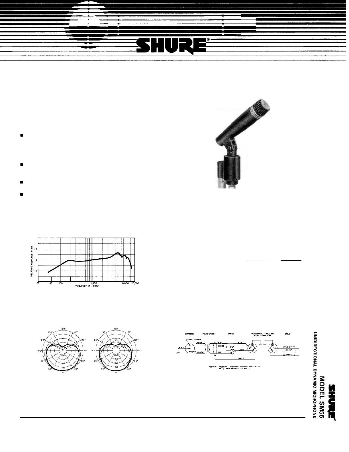
Frequency Response
40to15,000 Hz
(See Figure
1)
MODEL SM56
UNIDIRECTIONAL DYNAMIC MICROPHONE
impedance
Dual. Microphone rating impedance "L" is 38 ohms
(70 ohms actual) and microphone rating impedance
“H” is 150 ohms (300 ohms actual) for connection to
microphone inputs rated at 19 to 300 ohms. Shipped
with impedance switch at 150 ohms (“H” position)
TYPICAL FREQUENCY RESPONSE
FIGURE 1
Polar Pattern
Cardioid (unidirectional) response. Uniform with fre-
quency, symmetrical about axis (See Figure 2)
TYPICAL POLAR PATTERNS
FIGURE 2
Output Level (at 1,000 Hz)
Open Circuit Voltage* . . . . -82.0 dB
(.079 mV)
Power Level** . . . . . . . . . . . -56.5 dB
*0 dB = 1 volt per microbar
**0 dB = 1 milliwatt per 10 microbars
Switch
Built-in slotted impedance switch
INTERNAL CONNECTIONS
FIGURE 3
Cartridge Shock Mount
Internal rubber vibration-isolator
“L” “H”
- 75.5 dB
(.167 mV)
-56.5 dB
222 HARTREY AVENUE, EVANSTON, ILLINOIS 60204 U.S.A.
Copyright 1985, Shure Brothers Inc.
27A2115(ED)
l TELEPHONE: (312)866-2200 • CABLE: SHUREMlCRO
Printed in U.S.A.
Cable
6.1m (20 ft) two-conductor shielded, with professional three,-socket audio connector designed to
mate with Cannon XL series, Switchcraft A3 (Q.G.)
series, or equivalent connector
Swivel and Shock Mount Assembly
Positive action, permits tilting head through 180°,
shock mounted with internal rubber vibration-
isolator, suitable for mounting on stand with 5/8”-27
thread
Case
Dark gray enameled die casting and polycarbonate
with stainless steel screen
The microphone shall be provided with a vibrationisolator in combination with a swivel adjustable
through 180°. The microphone shall be suitable for
mounting on a stand with a 5/8”-27 thread. The
microphone shall also be provided with a detachable
6.1 m (20 ft) two-conductor shielded cable with a professional three-socket audio connector* at the microphone
end.
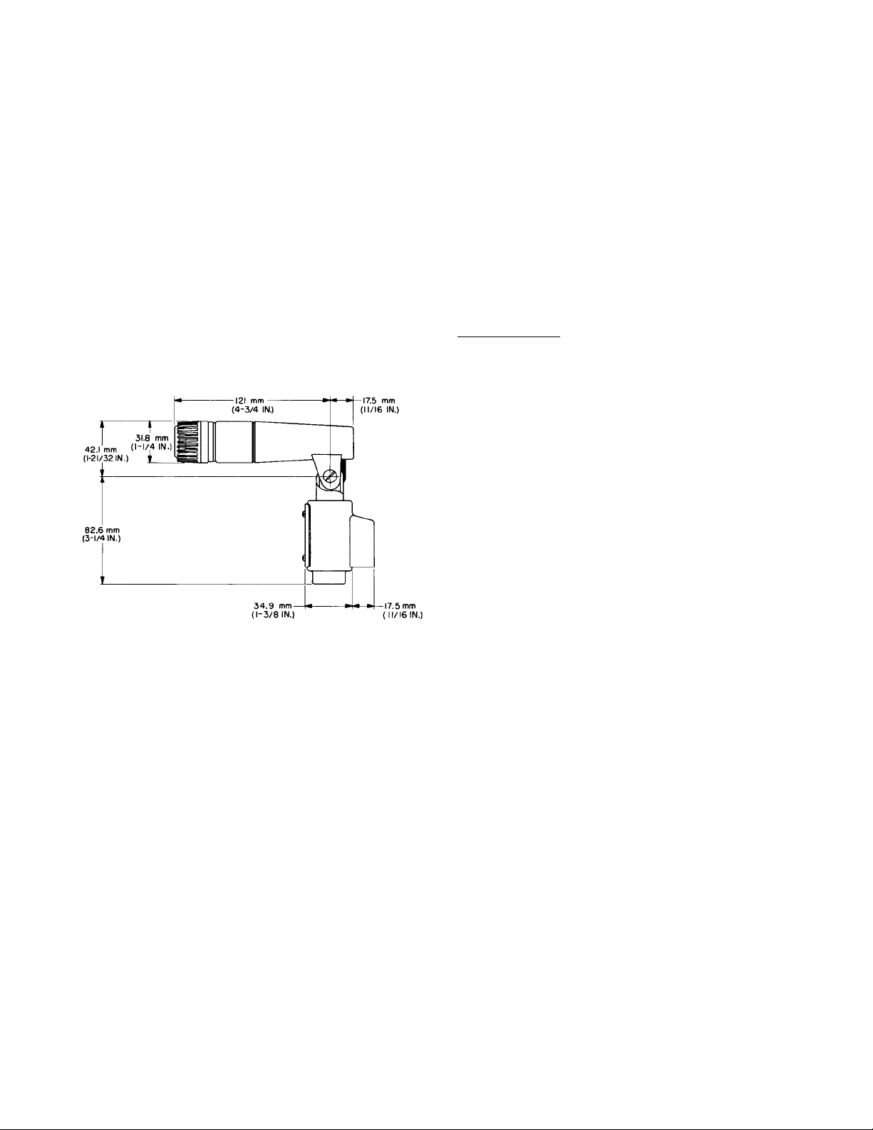
The overall dimensions of the microphone shall be 125
mm (4-29/32 in.) in length, 31.4 mm (1¼ in.) in width, and156 mm (6-1/8 in.) in depth.
The microphone shall be the Shure Model SM56 or
equivalent.
Dimensions
See Figure 4
OVERALL DIMENSIONS
FIGURE 4
Net Weight (less cable)
1.01 kg (2 lb, 3½ oz)
Packaged Weight
1.33
kg (2 lb, 15 oz)
ARCHITECTS’ SPECIFICATIONS
The microphone shall be a moving-coil (dynamic) type
with a frequency response of 40 to 15,000 Hz. The unit
shall have a cardioid polar characteristic. The cancellation at the sides shall be approximately 6 dB, and the
cancellation at the rear shall be 15 to 20 dB. The
microphone shall be a dual-impedance unit with rated
impedances of 38 ohms and 150 ohms for connection to
microphone inputs rated at 19 to 300 ohms. Impedance
change shall be by means of a three-position
Impedance-Off switch for setting the microphone for 38
ohms (“L” position), 150 ohms (“H” position), or Off (“O”
position).
The microphone output shall be -56.5 dB where 0 dB
= 1 milliwatt per 10 microbars.
“Designed to mate with a Cannon XL series, Switchcraft A3 (Q.G.)
series or equivalent connector.
IMPEDANCE SELECTION
Remove the impedance switch cover plate by removing the two 2-56 binding head machine screws at each
end of the cover plate. The center position of the slotted
Impedance-Off switch is the Off position;
counterclockwise (as shipped) is the 150-ohm position;
clockwise is the 38-ohm position. Select the desired
switch position, replace the impedance switch cover
plate, and secure with the two 2-56 binding head
machine screws.
OPTIONAL ACCESSORIES
Windscreen
Extension Cable
Dynamic Cartridge
Cable and Plug Assembly
Plug Element
GUARANTEE
. . . . . . . . . . . . . . . . . . . . . . .A2WSA
. . . . . . . . . . . . . . . . . . . . . . . . .C20H
REPLACEMENT PARTS
............................
....................
R57
C2OD
............................. 65A67
This Shure product is guaranteed in normal use to be
free from electrical and mechanical defects for a period
of one year from date of purchase. Please retain proof
of purchase date. This guarantee includes all parts and
labor. This guarantee is in lieu of any and all other
guarantees or warranties, express or implied, and there
shall be no recovery for any consequential or incidental
damages.
SHIPPING INSTRUCTIONS
Carefully repack the unit, have it insured, and return it
prepaid to:
Shure Brothers Incorporated
Attention: Service Department
222 Hartrey Avenue
Evanston, Illinois 60204
If outside the United States, return the unit to your
dealer or Authorized Shure Service Center for repair.
The unit will be returned to you prepaid.
 Loading...