

Page 1

MODEL SM15
UNIDIRECTIONAL HEAD-WORN CONDENSER MICROPHONE
MODEL SM15
UNIDIRECTIONAL HEAD-WORN
CONDENSER MICROPHONE
The Shure Model SM15 is a unidirectional headworn
electret condenser microphone primarily designed
for high-quality sound reinforcement applications. Its
high output and excellent acoustic properties also
make it a good choice for use in broadcasting, talkback, paging, communications, and data entry. The
SM15 is one of the few headworn microphones available today that closely approximates the best in handheld/stand-mount vocal microphones.
The SM15’s smooth, natural voice frequency
response makes it ideal for drummers, keyboard artists and other musicians requiring a vocal microphone
with all the qualities of a hand-held unit-the SM15
can be used under noisy conditions without loss or
masking of voice signals.
A small, lightweight, rugged and reliable unit, the
SM15 has provisions for mounting to a supplied headband with cushioned arms. The dual steel headband
holds securely without causing discomfort for active
microphone users. A pivot housing permits the microphone boom to be moved 20° in any direction, and the
distance between the microphone and pivot can be
changed by up to 89 mm (3-1/2 in.).
The SM15’s amplifier is constructed of high-impact
ARMO-DUR®, making it compact, lightweight, and
extremely rugged. It can easily be clipped to a belt or
waistband, or slipped into a pocket. It is powered by a
readily available 9-volt battery or by phantom power
from an external source providing 5-52 Vdc (such as a
Shure PS1A power supply or M267 or M268 microphone mixer). The amplifier incorporates extensive
RF and hum shielding to reduce the effects of electromagnetic and electrostatic interference. Connections
between the microphone and amplifier are made
through a miniature 3-pin connector.
The SM15 is supplied with a windscreen to protect
against wind noise and explosive breath sounds, and a
foam-lined carrying/storage case.
Features
• Close-talk operation and unidirectional polar pattern for effective noise reduction
• High sound pressure level capacity
• Smooth, natural frequency response, tailored for
voice
• Low distortion and wide dynamic range characteristics under various load impedances
• Wide-range phantom powering accepts all commonly
used voltages; can also be battery-powered
• Acoustically isolated for maximum feedback freedom
• Locking adjustment knob permits 20° boom pivot
in any direction. Boom mounts on either side of
headband
• Boom length adjustment through 89 mm (3-1/2 in.)
• Dual headband design plus serrated arms minimize
accidental movement
• Lightweight design prevents user fatigue
• No interference with eyeglasses
• Ruggedly constructed of stainless steel, aluminum
and high-impact thermoplastic
• Usable over wide range of temperature and humidity conditions
• Amplifier assembly can be pocketed, strapped to
body, or clipped to belt or waistband
ASSEMBLY
Assemble the SM15 for use as follows:
1. Twist the lower headband arms 90° so they are
perpendicular to the headband. As supplied, the
retaining clip is positioned for left side operation as
shown in Figure 1. For right side usage (see photo),
remove the retaining clip and attach it to the other
(unused) hole in the headband arm so the screw is
at the top.
2. Snap the microphone pivot housing into the retaining
clip with the pivot adjustment knob upward and the
microphone toward the front. Loosen the pivot adjustment knob, position the boom so that the microphone is near where the side of the mouth will be,
and tighten the pivot adjustment knob.
3. Place the assembled microphone on the user’s head
and pull the headband arms downward until they
rest against the head just over the ears.
4. Loosen the pivot adjustment knob and position the
microphone as close as possible to the corner of
the mouth. IMPORTANT: For optimum close-talking
operation, the microphone should be less than 25mm
(1 in.) from the corner of the mouth. Be sure to
position the microphone at the corner (not the center) of the mouth to eliminate explosive breath
sounds (“pop”). Tighten the adjustment knob.
222 HARTREY AVE., EVANSTON, IL 60202-3696 U.S.A. • PHONE (312) 866-2200 • TELEX: 4330191 • FAX (312) 866-2279
Copyright 1987. Shure Brothers Inc. Printed in U.S.A.
27A2371 (GB) U.S. Patent 4,039,765
Page 2
5. Connect the SM15 microphone cable to the amplifier assembly.
6. Insert a fresh 9-volt battery in the amplifier battery
compartment (see Batteries section) and connect
the amplifier 3-pin XLR connector to the mixer input
connector, or phantom-power the SM15 by connecting the amplifier (without battery) to a microphone powersupply providing 5 to 52 Vdc phantom
voltage. This can be a separate phantom power
supply, or a mixer or amplifier with provisions for
phantom powering (see Phantom Powering section).
7. Place the amplifier assembly in the desired position
(see Amplifier Mounting section).
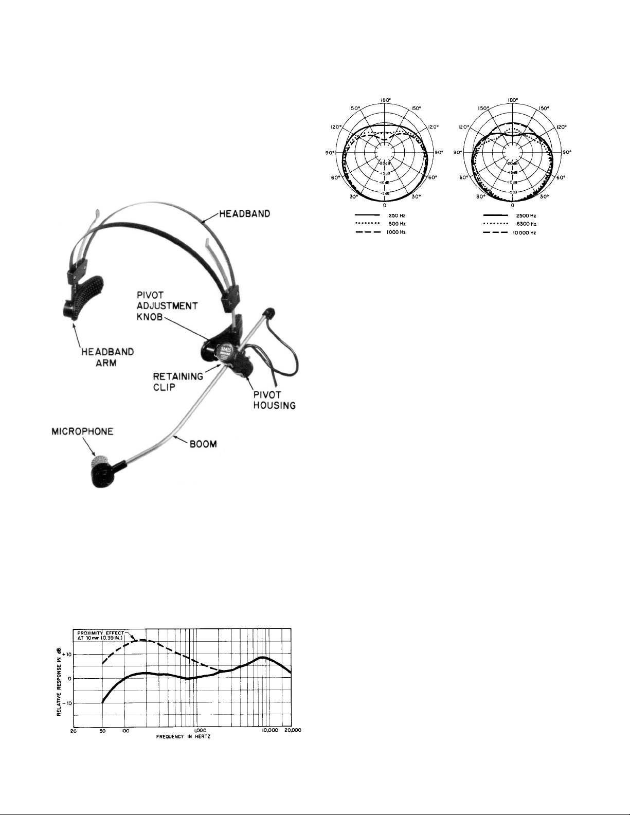
Polar Pattern
Cardioid (unidirectional) response–uniform with
frequency, symmetrical about axis (see Figure 3)
TYPICAL POLAR PATTERNS
FIGURE 3
Output Impedance
Rated at 150 ohms (95 ohms actual)
Recommended minimum load impedance: 800 ohms
(may be used with loads as low as 150 ohms with
reduced clipping level)
SM15 POSITIONED FOR LEFT SIDE OPERATION
FIGURE 1
SPECIFICATIONS
Type
Condenser (electret bias)
Frequency Response (at 76 mm–3 in.)
50 to 15,000 Hz (see Figure 2)
Output Level (close-talked at 1,000 Hz)
Open Circuit Voltage
–40.5 dB (0.9 mV) at 610 mm (24 in.)
–39 dB (1.1 mV) at 10 mm (0.39 in.)
(0 dB = 1 volt per 100 microbars)
Clipping Level (at 1,000 Hz)
800-ohm Load................. –13 dB (0.22V)
150-ohm Load................ –27 dB (0.045V)
Total Harmonic Distortion
Less than 1% (138 dB SPL at 1,000 Hz into 800-ohm
load)
Maximum SPL
141 dB with 800-ohm load
130 dB with 150-ohm load
Hum Pickup
Less than or equal to 0 dB equivalent SPL in a 1
millioersted field (60 Hz)
Output Noise (equivalent sound pressure levels; measured with true rms voltmeter)
32 dB typical, A-weighted
38 dB typical, weighted per DIN 45 405
Dynamic Range
109 dB (maximum SPL to A-weighted noise level)
TYPICAL FREQUENCY RESPONSE
FIGURE 2
Signal-to-Noise Ratio
62 dB (IEC 651) at 94 dB SPL
Phasing
Positive pressure on diaphragm produces positive
voltage on pin 2 relative to pin 3
Power
Battery: 9 Vdc (type 1604A, alkaline recommended);
0.33 mA current drain; approximately 1600 hours
continuous use with fresh battery
Page 3

Phantom Voltage: 5 to 52 Vdc; 0.33 mA current
drain
Protected against reverse voltage application
Environmental Conditions
Operating Temperatures ... –18° to 60°C (0° to
140 °F)
Storage Temperatures .. –29° to 66°C (-20° to
150 °F)
Cables
Microphone: 1.2m (4 ft) attached, two-conductor,
shielded with miniature 3-pin connector designed to
mate with Switchcraft TA3 series or equivalent.
Amplifier: 3m (10 ft) attached, two-conductor,
shielded with 3-pin XLR audio connector designed
to mate with Cannon XL series, Switchcraft A3
(Q-G) series or equivalent connectors
Case
Microphone: Black thermoplastic microphone and
pivot housing, anodized aluminum end caps, stainless steel grille and boom
Amplifier: Black molded high-impact ARMO-DUR
with detachable belt clip
Dimensions
See Figure 4
To insert the battery, depress the ridged area of the
case and swing the hinged door outward. Insert the
battery in the compartment, battery terminals toward
the hinge and positive terminal inward (the negative
contact is marked inside the compartment). Depress
the battery slightly and hook it under the “ledge” in the
compartment. The ledge and spring contacts will retain
the battery even if the door or hinges are damaged.
Close and lock the door. Note that the door will not
lock if the battery is incorrectly inserted; the positive
and negative contact areas accept only the corresponding battery terminals.
To prevent battery drain when the unit is not in use,
the battery should be removed or stored in the battery
compartment upside down (battery terminals facing in
the opposite direction from the amplifier contacts)
and positive battery terminal inward. If the unit is not
to be used for a prolonged period, the battery should
be removed to prevent possible damage from leakage.
Note that no current is drawn from the battery when
a phantom voltage higher than the battery voltage is
applied. Phantom power can be used whether or not a
®
battery is in the amplifier.
PHANTOM POWERING
The SM15 is designed for phantom powering by
virtually any microphone power supply providing 5 to
52 Vdc phantom voltage. The Shure PS1A power supply will provide phantom power to one or two SM15
microphones. Phantom powering uses the balanced
audio cable pair to carry the supply current to the
microphone, and the cable shield as a ground return.
Use only high-quality extension cables, as intermit-
tent shorts between broken shield wires and balanced
conductors will cause objectionable noise transients
in the system. A reliable ground path is essential for
the same reason.
OVERALL DIMENSIONS
Figure 4
Net Weight
Microphone: 78 grams (2.8 ounces)
Amplifier: 270 grams (9.45 ounces)
BATTERIES
The SM15 is normally powered by a 9-volt battery
(alkaline types are recommended). Under normal
operating conditions, a fresh alkaline battery should
provide approximately 1600 hours of operation.
Recommended battery types are:
Duracell MN1604 NEDA 1604A
Eveready 522 IEC 6LR22
Bright Star 7590 Japanese 6AM6
Ray-O-Vac A1604 Varta 4022
Radio Shack 23-553 U.S. Military BA3090
Note that the SM15 is designed without an on-off
switch; the amplifier is on whenever a “good” battery
is inserted or phantom power is applied. The highly
efficient circuit can operate for two months continuously with a fresh alkaline battery.
MICROPHONE LOADING
A minimum load impedance of 800 ohms should be
used for maximum signal handling and minimum distortion. The load can be as low as 150 ohms, but a
reduction in output clipping level will result. It should
be noted that the power supply itself may add loading
(3300 ohms in the Shure PS1A) to the microphone.
WIND NOISE
A head-worn microphone generally needs a windscreen for proper operation. When used outdoors under
windy conditions, the SM15’s acoustic foam windscreen
helps eliminate the unpleasant “rushing” noise associated with outdoor miking.
AMPLIFIER MOUNTING
Most SM15 applications require that the amplifier
be worn on the body. The spring-loaded belt clip holds
the amplifier to a belt, skirt or trouser waistband, or
inside pocket.
The belt clip can be removed from the case and the
amplifier placed on a nearby horizontal surface or
worn in an inside pocketwithoutany retention method.
Clip removal requires disassembly of the case (two
Phillips head screws in the case and two slotted head
screws in the connector collar).
Page 4

BLOCK DIAGRAM
Figure 5
Note that the “W-shaped” belt clip permits the power
supply to be worn with the cable end either upward or
downward, depending on the speaker’s comfort and
the particular application.
CIRCUIT DESCRIPTION
A block diagram of the SM15 is shown in Figure 5.
The capacitor cartridge is followed by a field-effect
transistor impedance conversion stage. The FET output is coupled through a two-conductor, shielded cable
and miniature three-pin connectors to the amplifier
assembly. The first stage in the amplifier is an RFI
filter, whose output enters a compound transistor, Class
A, emitter-follower amplifier and 12 dB/octave active
high-pass filter. The circuit output is transformercoupled, providing a balanced output. The preamp
output is also RFI-filtered.
A constant-current power supply circuit regulates
the powering voltage, allowing maximum battery life
and operation over the widest range of phantom voltages. Reverse voltage protection diodes automatically select phantom powering when the applied phantom voltage exceeds the battery voltage, and guard
against miswired cables and equipment. The circuit
provides low noise, low distortion, wide frequency
response and dynamic range, low output impedance,
and reliable operation over a wide range of working
environments.
TROUBLESHOOTING
The following steps should should be taken if prob-
lems arise.
1. Check to see that battery voltage (or external voltage on pins 2 and 3 of cable output connector)
is adequate.
2. If a second SM15 is available, interchange microphones and amplifiers to localize the problem.
3. Remove the amplifier case cover (four screws: two
Phillips head in the case and two slotted head in
the connector collar) and check the voltages against
those given in the circuit diagram.
4. Check the microphone and amplifier cables for
continuity.
FURNISHED ACCESSORIES
Windscreen.......................... 49A74A
Carrying Case....................... 65A1578
REBLACEMENT PARTS
Microphone Cartridge .................... R145
Headband Assembly .................. 90A3997
Headband Retaining Clip .............. 53A1801C
Battery Compartment Door.............. 65A1536
Belt Clip ............................ 44A279
Page 5

AMPLIFIER CIRCUIT DIAGRAM
AMPLIFIER PRINTED
CIRCUIT BOARD
AMPLIFIER REPLACEMENT PARTS LIST
Reference
Designation
A1 90A4005 Printed Circuit Board Assembly None
C7 86B651
D1 86B429 Diode, Current Regulator,
D2, D3 86A415 Diode, Computer, 75V, 0.4A
J1 95A8077 Connector, Receptacle,
L1, L2 80A253 Ferrite Bead Ring Stackpole 57-0180
P1 90BT2600 Connector, Receptacle,
Q1 86A348 Transistor, PNP Motorola 2N5087
Q2 86A350 Transistor, NPN Motorola 2N5210
T1 51B286 Transformer, Audio None
Part
Number
Description Commercial
Capacitor, Tantalum, 33 µF, 6.3V
100V, 0.33 mA
75V, 0.4A
Miniature 3-pin
3-pin XLR
Alternate
Motorola 1N5287
Motorola 1N5287
TI/GE
1N4148
Switchcraft TB3M
None
W1 90A3792 Cable and Connector Assembly
(incl. P1)
None
 Loading...