

Page 1
MODEL SM14A
HEAD-WORN MICROPHONE WITH RECEIVERS
GENERAL
The Shure Model SM14A Professional Head-Worn Microphone with Receivers is a low-impedance, unidirectional, dynamic microphone with two integral earphone
assemblies. Each receiver assembly has its own
transformer and phone plug for monitoring separate
sound sources. Designed for sports and news announcing, interviewing and intercommunication systems, and for special-events remote broadcasting, the
SM14A offers convenient, hands-free operation without
user fatigue. A close-talking microphone, the SM14A
may be used under noisy conditions without loss or
masking of voice signals. The SM14A is a small, lightweight, rugged and reliable unit, with provisions for
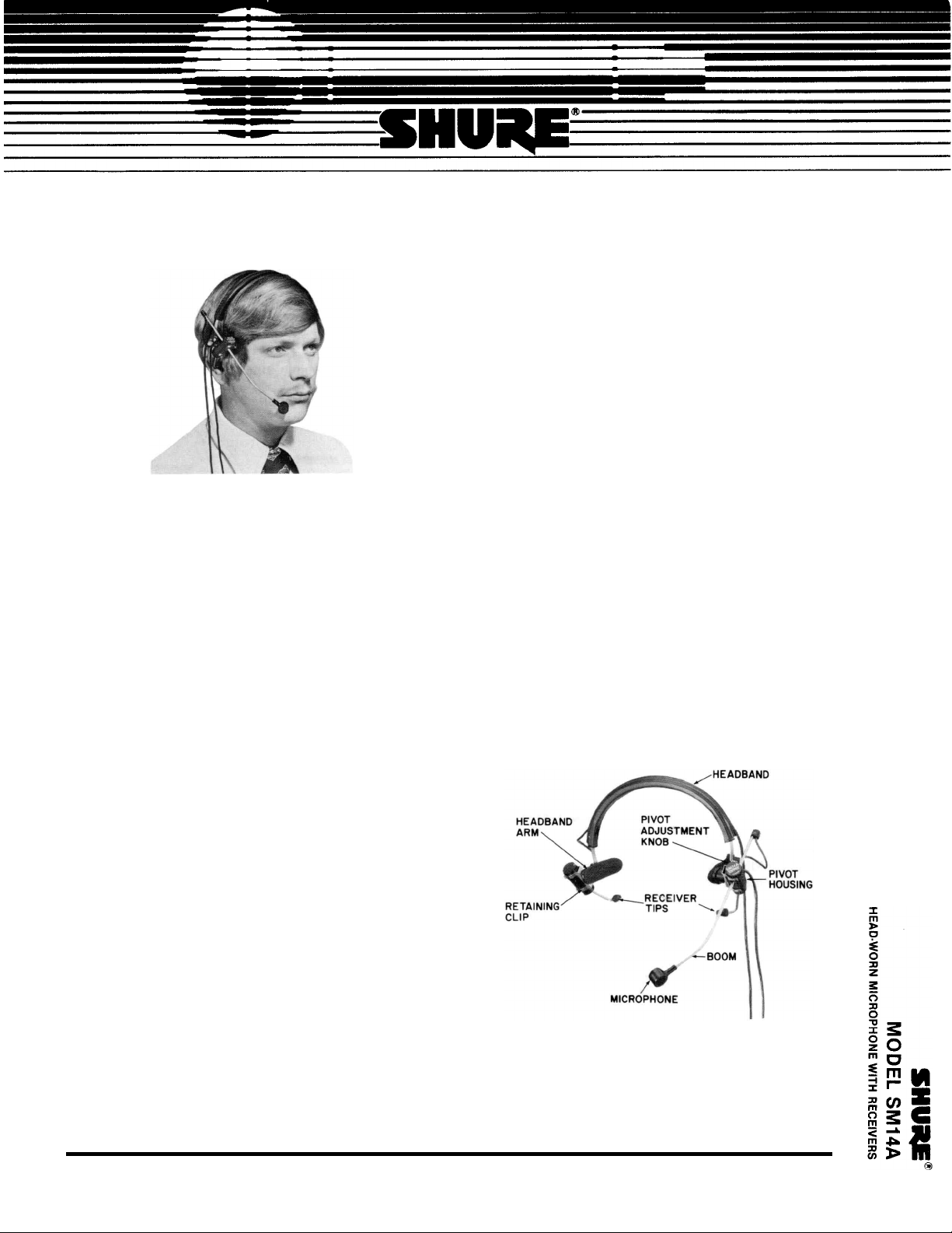
mounting to a supplied cushioned headband. A pivot
housing permits the microphone boom to be moved
20° in any direction, and the distance between the
microphone and pivot to be changed by up to 89 mm
(3 ½ in.). The receiver ear tubes, attached to the bottoms of the pivot housings, may be moved through a
55° arc. A miniature windscreen to protect against
wind noise and explosive breath sounds, and three
connector belt clips are also supplied.
ASSEMBLY
Assemble the SM14A for use as follows:
1. Twist the lower headband arms 90° so they are
perpendicular to the headband. For left side usage,
the microphone retaining clip will be on the left side
of the user’s head; for right side usage, the
microphone clip will be on the right (see photo and
Figure 1).
2. Snap the microphone pivot housing into the
retaining clip with the pivot adjustment knob upward
and the microphone toward the front. Loosen the
pivot ad-justment knob, position the boom so that
the microphone is near where the side of the mouth
will be, and tighten the pivot adjustment knob.
3. Snap the pivot housing of the second receiver
assembly into the remaining retaining clip with the
receiver tip downward. Insert the receiver cable in the
groove across the top of the headband. In this way,
the two cables will be adjacent to each other.
4. Place the assembled microphone on the user’s head
and pull the headband arms downward until they
rest against the head just over the ears. Position the
receiver tips at the entrances to the ears. (Make
cer-tain cables are free of receiver ear tubes.)
Model SM14A Features:
Close-talk operation and unidirectional polar pattern
§
for effective noise reduction
§ Smooth natural voice frequency response
§ Locking adjustment knob permits boom to pivot 20°
in any direction
§ Boom length adjustment through 89 mm (3 ½ in.)
range
§ Twin receivers monitor separate sound sources
§ Receiver ear tubes adjustable through 55° arc
§ Light weight plus padded headband eliminate user
fatigue
§ Does not interfere with eyeglasses
§ Ruggedly constructed of stainless steel, aluminum
and high-impact thermoplastic
§ Convenient, secure clips attach connectors to belt
or clothing
222 HARTREY AVE., EVANSTON, IL 60204 U.S.A. • AREA CODE 312/866-2200 • CABLE: SHUREMICRO • TWX: 910-231-0048 • TELEX: 72-4349
Copyright 1984, Shure Brothers Inc. U.S. Patent 4,039,765
27A2035 (DA) Printed in U.S.A. Printed in U.S.A.
SM14A POSITIONED FOR LEFT SIDE OPERATION
FIGURE 1
Page 2
WARNING
Sustained high volume levels in conjunction with
a tightly fitting receiver tip may adversely affect
the user’s hearing. Make certain the volume is set
to a comfortable listening level and position the
receiver tip at the entrance of the ear.
5. Loosen the pivot adjustment knob and position the
microphone as close as possible to the corner of the
mouth. For optimum close-talking operation, the
microphone should be less than 25 mm (1 in.) from
the corner of the mouth. Be sure to position the
microphone at the corner (not the center) of the
mouth to eliminate explosive breath sounds (“pop”).
Tighten the adjustment knob.
6. Snap the microphone connector belt clip over the
groove in the 3-pin audio connector and the receiver
connector belt clips over the grooves in the phone
plugs. The clips can now be fastened to the user’s
belt or other clothing. Attach the 3-pin audio connector to the microphone cable and the phone plugs to
the monitoring unit cables.
7. NOTE: A decrease in receiver output may be due to
clogging of the receiver tip. The tip may be cleaned
by removing it from the ear tube and inserting a
toothpick or similar device through the tip hole. If
clogging is apparent in the ear tube, carefully remove
the obstruction from the ear tube tip. CAUTION: Do
not disturb the foam damping material located just
inside the ear tube tip.
SPECIFICATIONS
MICROPHONE
Type
Dynamic, Close-Talking
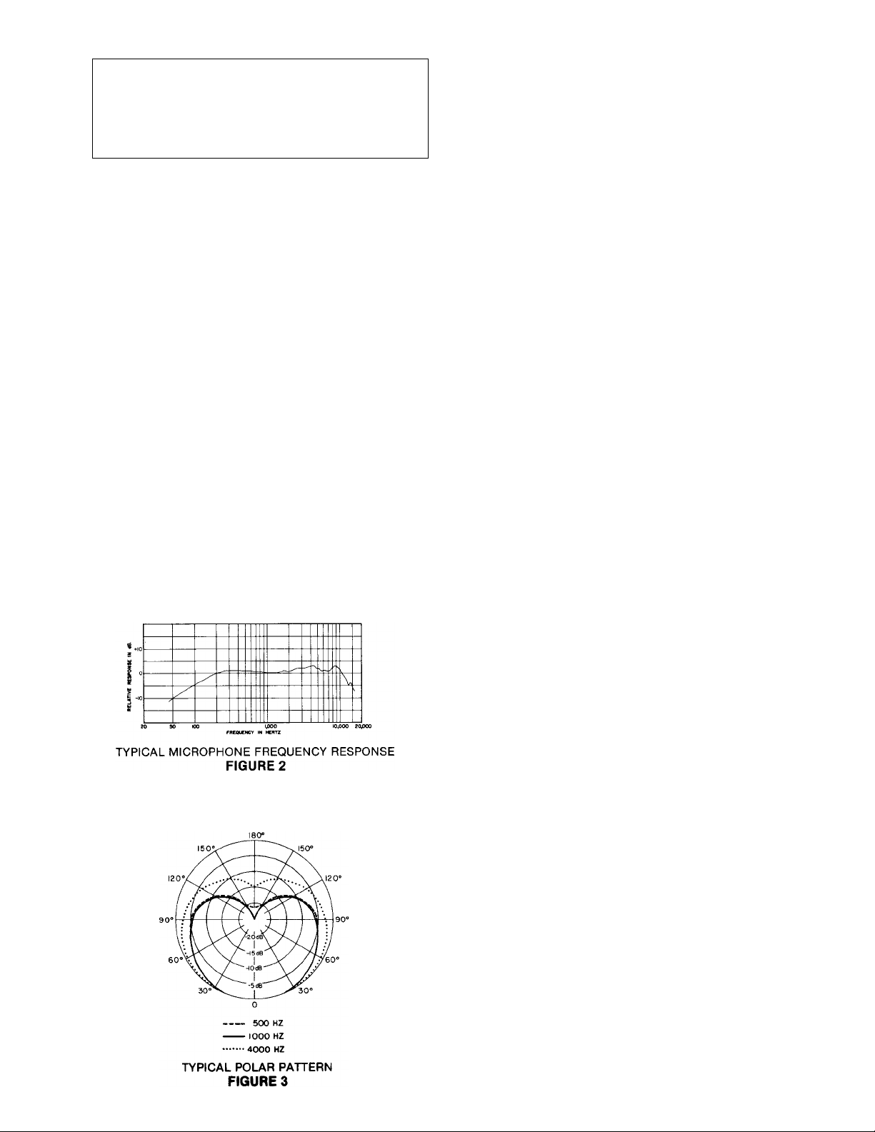
Frequency Response (at 8 mm [5/16 in.])
50 to 15,000 Hz (see Figure 2)
Impedance
Microphone rating impedance is 150 ohms (200 ohms
actual) for connection to microphone inputs rated at
19 to 300 ohms
Output Level (close-talked at 1,000 Hz)
Open Circuit Voltage ........ -47.0 dB (4.5 mV)
(0 dB = 1 volt per 100 microbars)
Power Level .............. -66.0 dB
(0 dB = 1 milliwatt per 10 microbars)
Hum Sensitivity (typical)
38.4 dB equivalent SPL in a 1 millioersted field
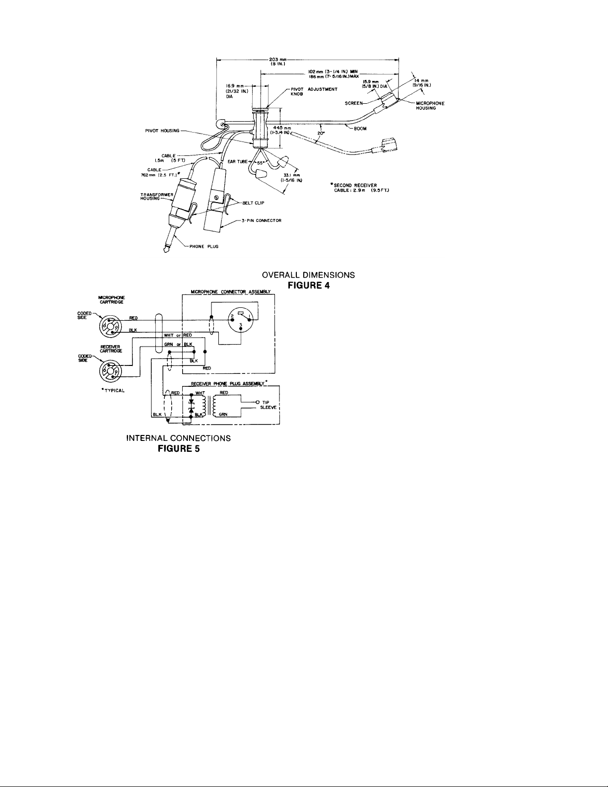
Phasing
Positive pressure on diaphragm produces positive
voltage on pin 2 of microphone connector
Connector
Professional three-pin audio connector designed to
mate with Cannon XL series, Switchcraft A3 (Q.G.)
series or equivalent connectors.
RECEIVERS
Type
Dynamic
Frequency Response
70 to 12,000 Hz
Impedance
2,000 ohms at 1 kHz (200-ohm cartridges with
matching transformers in phone plugs)
Output Level
105 dB SPL with 1.4V at 1 kHz (1.0 mW into 2 cc
cavity)
Polar Pattern
Cardioid (unidirectional) response–uniform with frequency, symmetrical about axis (see Figure 3)
Phasing
Positive voltage on phone plug tips produces
positive pressure in ear tubes
Connector
Phone plugs (contain matching 200:2,000 ohm
transformers)
GENERAL
Cable
Non-detachable, 1.5m (5 ft), four-conductor, shielded,
plastic-jacketed; 762 mm (2.5 ft), two-conductor
receiver cable attached to microphone connector.
Non-detachable, 2.9m (9.5 ft), two-conductor cable
attached to second receiver assembly.
Case
Black thermoplastic microphone and pivot housings,
anodized aluminum end caps, stainless steel grille,
ear tubes and boom
Dimensions
See Figure 4
Net Weight
103 grams (3½ ounces) less cables and connectors
Packaged Weight
890 grams (1 lb, 15 oz)
Page 3
ARCHITECTS’ SPECIFICATIONS
The microphone with receivers shall be the Shure
Model SM14A or equivalent. The microphone shall be a
moving-coil (dynamic) type with a frequency response of
50 to 15,000 Hz. The unit shall have a cardioid polar
characteristic. The cancellation at the rear shall be 15
to 20 dB. The microphone shall be low impedance with a
rated impedance of 150 ohms for connection to
microphone inputs rated at 19 to 300 ohms.
The microphone output shall be —66.0 dB where
0 dB = 1 milliwatt per 10 microbars.
The receivers shall be dynamic types with a frequency response of 70 to 12,000 Hz. The receivers shall
be supplied with integral connector-mounted matching
transformers designed with an impedance of 2,000
ohms.
own 2.9 m (9.5 ft) cable. The microphone shall also be
provided with a headband, three connector belt clips,
and a foam windscreen.
The overall dimensions of the microphone shall be
203 mm (8 in.) in length and 44.5 mm (1-3/4 in.) in maximum height (pivot housing). The microphone housing
shall be 15.9 mm (5/8 in.) in diameter and 14 mm (9/16
in.) in height.
ACCESSORIES AND REPLACEMENT PARTS
The following furnished accessories and replacement
parts may be ordered through your Authorized Shure
Professional Products Dealer or from Shure Brothers
Inc.
Connector Belt Clip .................... RK200BC
Windscreen..........................RK184WS
Carrying Case.........................90A2255
Microphone Cartridge....................... R93
Receiver Cartridge......................... R94
Headband Assembly ....................90B3605
Receiver Tip ........................... RK190
GUARANTEE
This Shure product is guaranteed in normal use to be
free from electrical and mechanical defects for a period
of one year from date of purchase. Please retain proof
of purchase date. This guarantee includes all parts and
labor. This guarantee is in lieu of any and all other
guarantees or warranties, express or implied, and there
shall be no recovery for any consequential or incidental
damages.
The microphone with receivers shall be a head-worn
type, and shall be provided with a 1.5m (5 ft), nondetachable, four-conductor (two-conductor shielded)
microphone cable with a professional three-pin audio
connector designed to mate with Cannon XL series,
Switchcraft A3 (Q.G.) series or equivalent connectors.
An additional 762 mm (2.5 ft) cable length shall be provided between microphone and one receiver (phone
plug) connectors. The second receiver shall have its
SHIPPING INSTRUCTIONS
Carefully repack the unit, have it insured, and return it
prepaid to: Shure Brothers Incorporated
Attention: Service Department
222 Hartrey Avenue
Evanston, Illinois 60204
If outside the United States, return the unit to your
dealer or Authorized Shure Service Center for repair.
The unit will be returned to you prepaid.
 Loading...