

Page 1
SEK-2
Instruction Manual
for
Stylus Evaluation Kit
Manufactured by
SHURE BROTHERS INCORPORATED
222
Hartrey Avenue
Copyright
27A1339
1978,
(RE)
Shure Brothers Inc.
(95A851)
Evanston, Illinois
60204
Printed in
U.S.A.
Page 2
I.
INTRODUCTION
TABLE
OF CONTENTS
PAGE
.............................................................
1
II.
INSTALLATION AND ADJUSTMENT .2
A. Stylus Preparation
B.
Microscopeset-up ........................................................
Ill.
STYLUS EVALUATION .4
IV.
STYLUS PRESERVATION
V.
ADDENDA
A. Replacement Parts
B. 240-Volt Operation
C.
Guarantee
D. Shipping Instructions
...................................................................
...............................................................
........................................................
......................................................
....................................................
.......................................................
......................................................
....................................................
...........................................
2
3
-8
9
.9
9
.9
Page 3
/
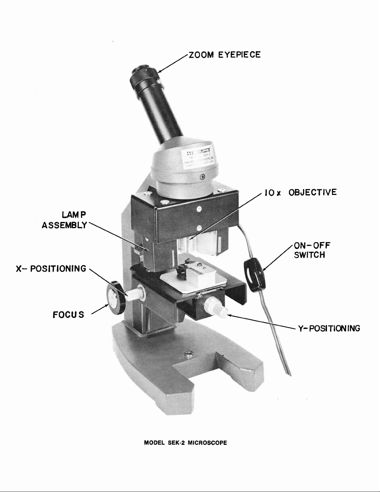
ZOOM
EYEPIECE
X-
SSEMBLY
A
POS
LAM
FOCU
P
S
ING
MODEL
SEK-2
MICROSCOPE
Page 4
I.
INTRODUCTION
The Shure Model SEK-2 Stylus Evaluation Kit consists of a high-quality microscope designed to evaluate the condition of phonograph cartridge stylus
tips. The SEK-2 provides a visual indication of the amount of wear on stylus
tips, enabling the customer to judge the necessity for replacing his stylus.
The SEK-2 includes a
optics, 10 to
clined eyetu be, precision focus control with end-of-focus slip clutch, and tension control to maintain focus. In addition, the microscope has x- and y-plane
horizontal stage positioning controls, and locating screws and hole on the stage
to facilitate stylus positioning. The SEK-2 also includes a two-lamp stage illuminator, stylus mounting block, stylus mounting plate, pliable material for
mounting other than Shure styli, dust cover, pencil-type flashlight (uses two
penlite batteries), and two light diffusers for the lamp assembly.
The Shure SEK-2 Microscope is a high-quality optical instrument. Reasonable care will insure years of excellent service. Keep the Microscope covered
when not in use.
20x zoom eyepiece, lox objective, rigid
100-200x monocular microscope featuring coated
"L"
stand construction, in-
Page 5
II.
INSTALLATION AND ADJUSTMENT
A. Stylus Preparation
The stylus cannot be evaluated properly unless the stylus tip is clean. To
clean the stylus, use a camel's-hair brush (No.
2
size or smaller) dipped lightly in grain (ethyl) alcohol or alcohol-distilled water solution; one part alcohol to
three parts distilled water is recommended. (WARNING: Commercial record or
stylus cleaning solutions may cause corrosion and permanent stylus damage.)
The alcohol solution will remove any sludge deposits which may have coated
the stylus tip. The brush bristles should be trimmed to a length no longer than
6
mm
(1/4
inch). Always brush the stylus with a forward movement from the rear
(terminal end of the cartridge) to the front. Never brush or wipe the stylus from
front to back or side to side. NOTE: All Shure styli may be cleaned this way.
For other brands of styli, obtain manufacturer's procedure before using the alcohol solution, as permanent damage may result.
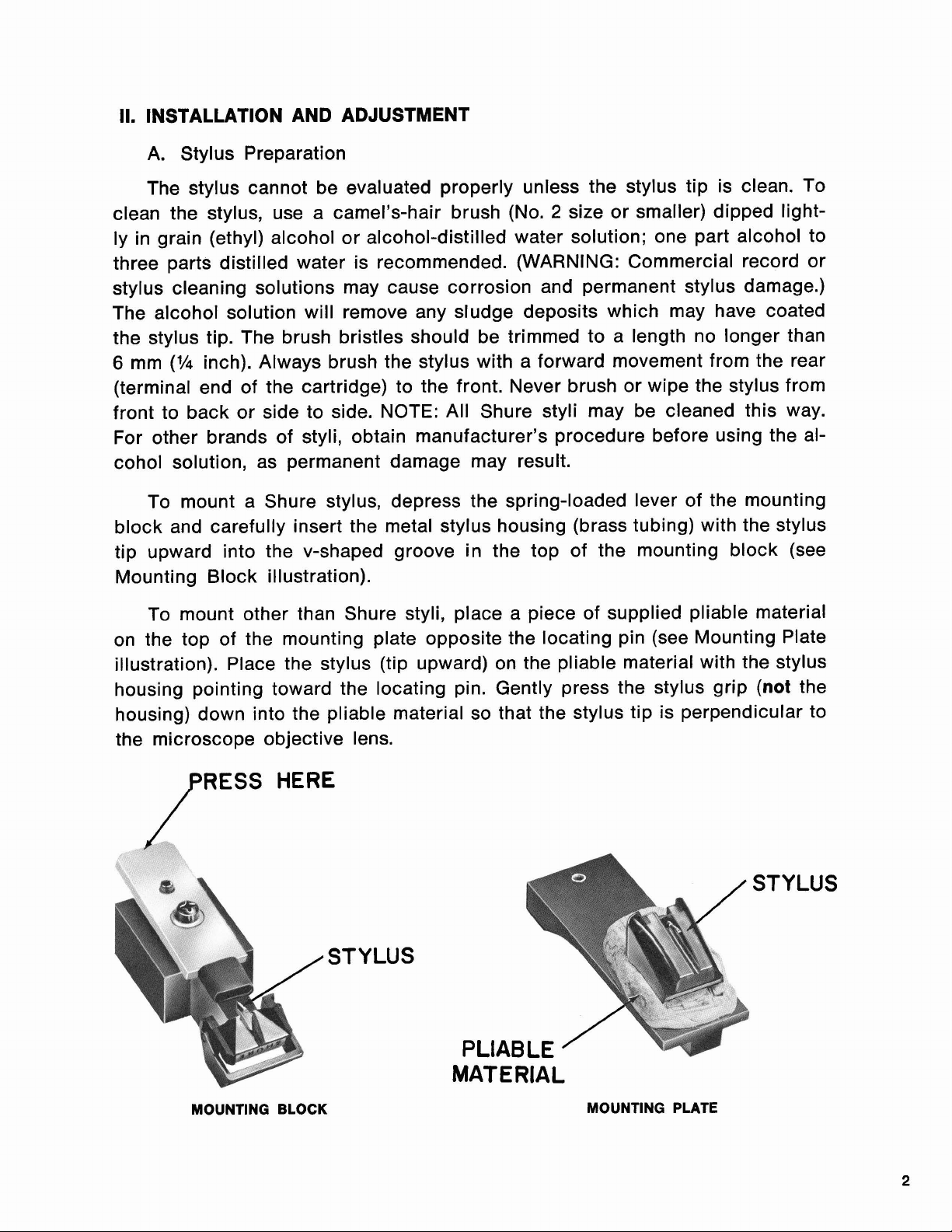
To mount a Shure stylus, depress the spring-loaded lever of the mounting
block and carefully insert the metal stylus housing (brass tubing) with the stylus
tip upward into the v-shaped groove in the top of the mounting block (see
Mounting Block illustration).
To mount other than Shure styli, place a piece of supplied pliable material
on the top of the mounting plate opposite the locating pin (see Mounting Plate
illustration). Place the stylus (tip upward) on the pliable material with the stylus
(not
housing pointing toward the locating pin. Gently press the stylus grip
the
housing) down into the pliable material so that the stylus tip is perpendicular to
the microscope objective lens.
STYLUS
MOUNTING BLOCK
MATERIAL
MOUNTING PLATE
Page 6

B.
Microscope Set-up
1. Place the microscope on a clean workbench or other firm surface
and install the lens barrel.
Lower the microscope stage by turning the black focus knob at
2.
either side of the vertical stand.
3.
Install the lamps in the lamp assembly. With the lamps pointing
downward, snap the lamp assembly over the vertical body tube and
slide the assembly upward as far as it will go.
4.
Plug the line cord into a 120 Vac, 50/60
cord switch to ON. Both lamps should light.
-
fective lamps with Type 6S6
6W, 120V, candelabra base; testing
Hz
outlet.* Rotate the line
(NOTE: Replace de-
cannot be performed unless both lamps are lit.)
5. If a Shure stylus is to be inspected, place the mounting block with
stylus on the microscope stage. With the mounting block centered
between the two raised socket-head capscrews and the mounting
block pin located in the hole in the platform, the stylus tip should
be almost directly below the objective lens.
6. If other than a Shure stylus is to be inspected, place the mounting
plate with stylus on the microscope stage. With the mounting plate
centered between the two raised socket-head capscrews and the
mounting plate pin located in the hole in the stage, the stylus tip
should be positioned near the objective lens.
7.
If a cartridge with a non-replaceable stylus is to be evaluated, first
determine whether the stylus tip, when the cartridge is lying upside-
down on the stage, will be perpendicular to the objective lens. If
it is perpendicular, proceed to step
8.
If it is not, place the cartridge
on top of a small piece of supplied pliable material on the mounting plate and gently press the cartridge body down until the stylus
tip is perpendicular to the objective lens.
8.
Turn the eyepiece zoom control to 10 (100x magnification) and use
the
x-
and y-positioning knurled knobs to center the stylus tip in
the eyepiece. The most convenient method of positioning the stylus
is to shine the beam of the pencil-type flashlight down through the
eyepiece to the stage. The stylus should be moved, using the x- and
y-positioning controls, until the beam shines directly on the stylus
tip. NOTE: Left to right and front to back movements are reversed
when viewed through the eyepiece.
9.
Using the black focus control at either side of the vertical stand,
3
mm
(%
bring the stylus tip to within
in.) of the objective lens.
CAUTION: Do not allow the stylus tip to touch the objective lens,
as the diamond tip will scratch the glass. Adjust the microscope
focus control to bring the tip into focus. When in focus, the stylus
(1h
tip should be approximately 6 mm
10. Rotate the eyepiece zoom control to 12
in.) from the objective lens.
(120x magnification).
*See
ADDENDA
for information on 240-volt operation.
Page 7

Ill.
STYLUS EVALUATION
Once the stylus tip is in focus, wear spots should be visible which correspond to the points of contact of the record surface. At
wear spots and the stylus tip are both in focus, resulting in so-called
eyes" where wear has occurred. Figures 1 through 4 illustrate the following stylus
conditions at this magnification:
120x magnification, the
"cat's
Figure
Figure 16.
Figure 2A.
Figure
Figure 3A.
Figure
Figure 4A.
Figure
IMPORTANT:
Study the wear areas of new and used
them with Figures 1 through
in three-dimensional views. In the microscope, only a small portion of the tip
-the tip wear area- is in focus at one time. The wear area appears as a
flat, two-dimensional representation (as in Figures 5 through 8). This is due to
the depth of field limitation and illumination of the microscope.
Increase the eyepiece zoom control to 20
as necessary. Figures 5 through 8 illustrate the following stylus conditions at
this magnification:
Figure 5A.
Figure 5B.
Figure 5C.
Figure 6A.
Figure 6B.
Figure 6C.
Figure 7A.
Figure 7B.
Figure 7C.
Figure 8A.
Figure
Figure 8C.
1A.
26.
36.
48.
8B.
Good spherical stylus
Worn spherical stylus
Good elliptical stylus
Worn elliptical stylus
Good hyperbolic stylus
Worn hyperbolic stylus
Good hyperelliptical stylus
Worn hyperelliptical stylus
New and used styli appear similar when casually observed.
styli in the microscope and compare
4.
Note that the figures show the entire stylus tips
(200x magnification) and refocus
Good spherical stylus
Slightly worn spherical stylus (recheck within 100 hours of
operation)
-
Badly worn spherical stylus (DO NOT USE
records)
Good elliptical stylus
Slightly worn elliptical stylus (recheck within
operation)
Badly worn elliptical stylus (DO NOT USE
records)
Good hyperbolic stylus
Slightly worn hyperbolic stylus (recheck within
operation)
Badly worn hyperbolic stylus (DO NOT USE
records)
Good hyperelliptical stylus
Slightly worn hyperelliptical stylus (recheck within
hours of operation)
Badly worn hyperelliptical stylus (DO NOT USE
age records)
will damage
100 hours of
-
will damage
100 hours of
-
will damage
-
100
will dam-
Page 8

GOOD SPHERICAL STYLUS
FIGURE
1A
WORN SPHERICAL STYLUS
FIGURE
1B
GOOD ELLIPTICAL STYLUS
FIGURE
2A
WORN ELLIPTICAL STYLUS
FIGURE
28
Page 9

GOOD HYPERBOLIC STYLUS
FIGURE
GOOD HYPERELLIPTICAL STYLUS WORN HYPERELLIPTICAL STYLUS
FIGURE 4A FIGURE 48
3A
WORN HYPERBOLIC STYLUS
FIGURE 38
A
good reference check on stylus condition is to use a new replacement
stylus as a standard. With the new stylus as a reference, it is easier to evaluate
the condition of the used stylus. Another useful test in demonstrating stylus
wear to a customer is to maintain a selection of new and worn styli near the microscope so the customer can readily compare his own stylus with both photos
and actual styli.
Remember that stylus wear is a continuing, not an overnight, process.
A
stylus used for only a relatively short time (a few hundred hours) will have small
wear spots. However, this does not mean that it must be replaced. After gaining
some experience with various degrees of wear, it will become easier to make
assessments of styli conditions. Note that there may be bubbles or crystal structure on the stylus shank; these are not important, as
record.
the
only the stylus tip touches
Page 10

GOOD SPHERICAL
STYLUS
FIGURE
5A
SLIGHTLY WORN
SPHERICAL STYLUS
FIGURE
5B
BADLY WORN
SPHERICAL STYLUS
FIGURE
5C
GOOD ELLIPTICAL
STYLUS
FIGURE
6A
GOOD HYPERBOLIC
STYLUS
FIGURE
7A
SLIGHTLY WORN
ELLIPTICAL STYLUS
FIGURE
6B
SLIGHTLY WORN
HYPERBOLIC STYLUS
FIGURE
78
BADLY WORN
ELLIPTICAL STYLUS
FIGURE
6C
BADLY WORN
HYPERBOLIC STYLUS
FIGURE
7C
GOOD HYPERELLIPTICAL
STYLUS
FIGURE
8A
SLIGHTLY WORN
HYPERELLIPTICAL STYLUS
FIGURE
8B
BADLY WORN
HYPERELLIPTICAL STYLUS
FIGURE
8C
Page 11

IV. STYLUS PRESERVATION
The following recommendations will help the customer to maximize the life
of his stylus.
1.
Follow the turntable or tone arm manufacturer's instructions when
adjusting antiskating force.
Do not handle the tone arm
2.
while it is in operation. Accidentally
touching the tone arm while the turntable is rotating can cause the
arm to sweep across the record.
3.
If it is necessary to manually place the tone arm in the record groove
while the turntable is rotating, be sure to release it as soon as the
Dynamic Stabilizer sets down on the record or as the stylus engages
the record groove.
4.
Correct any improper setdown adjustment or malfunction of the
turntable changing mechanism to prevent the stylus from striking the
edge of the turntable or the record.
5.
Take care to pr6perly insert the stylus into the cartridge assembly
and the cartridge and shell assembly into the tone arm receptacle.
6.
Use proper vertical tracking force setting for each cartridge. Misadjustment of the tone arm counterbalance can cause excessive
vertical force beyond specified limits.
7. Do not use damaged records.
8.
When dusting the turntable, be sure to protect the stylus with the
stylus guard or Dynamic Stabilizer.
Page 12
V.
ADDENDA
A. Replacement Parts
Lamp Assembly
Mounting Block
Mounting Plate
Pliable Material
Lamp
*
---..-.--...---....-----------------------------------------------------------------
Lamp Diffuser (2)
Flashlight
*Available commercially as Type
B.
240-Volt Operation
--.-.-...---.-.....---------------------------------------------------
....----.-.-.-.-.-.-------------------------------------------------
-...-----...----...-------------------------------------.-------
.....---..-..--..-------...----------------------------------------
------...-.-...-.-.-------------------------------------.-----------
90A2300
90A2303
90A2305
80A220
95A486
.-...-.-....-.....----------------------------------------------
90LE1371
80A309
6S6
(6W,
120V,
candelabra base).
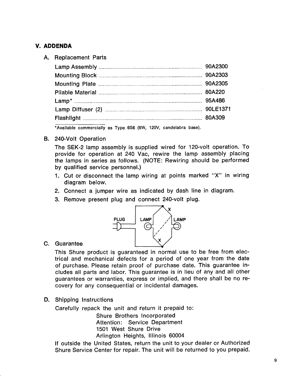
The SEK-2 lamp assembly is supplied wired for 120-volt operation. To
provide for operation at 240
the lamps in series as follows.
Vac, rewire the lamp assembly placing
(NOTE:
Rewiring should be performed
by qualified service personnel.)
1.
Cut or disconnect the lamp wiring at points marked
"X"
in wiring
diagram below.
2.
Connect a jumper wire as indicated by dash line in diagram.
3.
Remove present plug and connect 240-volt plug.
C.
Guarantee
This Shure product is guaranteed in normal use to be free from elec-
trical and mechanical defects for a period of one year from the date
of purchase. Please retain proof of purchase date. This guarantee includes all parts and labor. This guarantee is in lieu of any and all other
guarantees or warranties, express or implied, and there shall be no recovery for any consequential or incidental damages.
D.
Shipping Instructions
Carefully repack the unit and return it prepaid to:
Shure Brothers Incorporated
Attention: Service Department
1501 West Shure Drive
Arlington Heights, Illinois 60004
If
outside the United States, return the unit to your dealer or Authorized
Shure Service Center for repair. The unit will be returned to you prepaid.
 Loading...