

Shure SCM820 Digital IntelliMix User Manual

SCM820 Digital
Automatic Mixer
IntelliMix
®
27A20290 Rev. 1
©2013 Shure Incorporated
IMPORTANT SAFETY INSTRUCTIONS
1. READ these instructions.
2. KEEP these instructions.
3. HEED all warnings.
4. FOLLOW all instructions.
5. DO NOT use this apparatus near water.
6. CLEAN ONLY with dry cloth.
7. DO NOT block any ventilation openings. Allow sufficient distances for adequate ventilation and install in accordance with the manufacturer’s instructions.
8. DO NOT install near any heat sources such as open flames, radiators, heat registers,
stoves, or other apparatus (including amplifiers) that produce heat. Do not place any open
flame sources on the product.
9. DO NOT defeat the safety purpose of the polarized or groundingtype plug. A polarized
plug has two blades with one wider than the other. A grounding type plug has two blades
and a third grounding prong. The wider blade or the third prong are provided for your
safety. If the provided plug does not fit into your outlet, consult an electrician for replacement of the obsolete outlet.
10. PROTECT the power cord from being walked on or pinched, particularly at plugs, convenience receptacles, and the point where they exit from the apparatus.
11. ONLY USE attachments/accessories specified by the manufacturer.
12. USE only with a cart, stand, tripod, bracket, or table specified by the manufacturer, or sold with the apparatus. When a cart is used, use caution when
moving the cart/apparatus combination to avoid injury from tip-over.
13. UNPLUG this apparatus during lightning storms or when unused for long
periods of time.
14. REFER all servicing to qualified service personnel. Servicing is required when the apparatus has been damaged in any way, such as power supply cord or plug is damaged,
liquid has been spilled or objects have fallen into the apparatus, the apparatus has been
exposed to rain or moisture, does not operate normally, or has been dropped.
15. DO NOT expose the apparatus to dripping and splashing. DO NOT put objects filled with
liquids, such as vases, on the apparatus.
16. The MAINS plug or an appliance coupler shall remain readily operable.
17. The airborne noise of the Apparatus does not exceed 70dB (A).
18. Apparatus with CLASS I construction shall be connected to a MAINS socket outlet with a
protective earthing connection.
19. To reduce the risk of fire or electric shock, do not expose this apparatus to rain or
moisture.
20. Do not attempt to modify this product. Doing so could result in personal injury and/or
product failure.
21. Operate this product within its specified operating temperature range.
This symbol indicates that dangerous voltage constituting a risk of
electric shock is present within this unit.
This symbol indicates that there are important operating and maintenance instructions in the literature accompanying this unit.
WARNING: This product contains a chemical known to the State of California to cause cancer and birth
defects or other reproductive harm.
ii
Table of Contents
Table of Contents 1
Overview 2
IntelliMix® Operating Principles 2
Mixer Modes 2
Dual Mixer Operation 2
Audio Processing 2
Networking 2
Model Variations 2
SCM820 Description 3
Front Panel 3
Rear Panel 4
Operating the Mixer 5
Front Panel Modes 5
Audio Mute and Bypass 5
Monitoring 5
The SCM820 Graphical User Interface 6
Graphical User Interface (GUI) 6
Accessing the GUI 6
Installation 7
Rackmounting 7
Power 7
Typical Audio Connections 7
Configuring the Inputs and Outputs 8
Setting IntelliMix 9
IntelliMix Parameters 9
Mixer Mode Descriptions 9
Selecting the Mixer Mode 10
Single or Dual Mixer Operation 10
Application Examples 14
Creating a Link Group 14
Integrating with Other Systems 14
Configuring for Use with a Choir 14
Internet Calling 15
Logic 15
Troubleshooting 16
Event Log 17
Front-Panel Error Messages 17
Important Product Information 17
Information to the user 17
Patent Notice 17
Certifications 17
Signal Path Diagram 18
GUI Description 19
Navigation Bar 19
Input 20
Intellimix Tab 21
Output Tab 23
Link Group Tab 24
Preferences Tab 25
Log On Page 27
Specifications 28
Analog Connections 28
Digital Signal Processing 28
Networking 28
IP Ports and Protocols 29
Networking 11
Network Overview 11
Digital Audio Networking 11
Dante Software by Audinate 13
Dante Controller 13
Dante Virtual Soundcard 13
Furnished Accessories 29
Connector Diagrams 30
1
Overview
The Shure SCM820 is an 8-channel digital automatic mixer designed for use in speech applications, including sound reinforcement, broadcasting and audio
recording. It dramatically improves audio quality in any application where multiple microphones are required. The mixer uses
IntelliMix
®
technology to select
channels to open to the mix bus, while attenuating other channels. The mixing mode is selectable to allow a range of automatic mixing styles.
IntelliMix® Operating Principles
Expanding upon Shure's classic SCM810 IntelliMix technology, the digital
SCM820 delivers seamless automatic mixing by combining the following
functions:
• Noise Adaptive Threshold (NAT) manages the audio system by
distinguishing between dynamic audio (such as speech) and the noise
floor (such as air conditioning). It continuously adjusts the activation
threshold, so that only speech levels louder than the background noise
open a channel.
• MaxBus ensures that only one channel is opened per sound source,
reducing comb filtering for clear, intelligible speech.
• Number of Open Microphones Attenuation (NOMA) attenuates system
Dual Mixer Operation
The SCM820 can operate as a single or dual mixer:
Single Mixer: Channels are routed to a single mix bus that sends the same
audio to both Mix A and B outputs. This allows the same program to be
sent to different rooms or recording applications. Output gain, parametric
equalizer and limiter can be set separately for each mix.
Dual Mixer: Two separate buses provide independent automixes for each
mix output. This allows two entirely different mixes to result from the same
set of inputs. This is useful when the mixer is being used for two applications.
For example, set Mix A to Classic mode for sound reinforcement, and set Mix
B to Smooth for a broadcast feed. As a dual mixer, channels can be routed
to Mix A, Mix B, Mix A and B, or neither mix bus.
gain as additional channels are opened, providing consistent output levels
and better gain before feedback.
• Maintains the perceived ambient sound to achieve a natural sounding
audio program even during long pauses in conversation.
Audio Processing
The mixer provides adjustable input equalization, limiting and a parametric
output EQ (from the GUI) to optimize the sound for a given application.
Mixer Modes
The mixer operates in one of five Mix Modes: Classic, Smooth, Extreme,
Custom or Manual. The first three are factory settings that offer a range of
reliable automixing styles. IntelliMix is configurable in Custom mode and
turned off in Manual mode.
Classic
Classic mode emulates the default settings of the classic Shure SCM810
automixer. It is renowned for fast-acting, seamless channel gating and
consistent perceived ambient sound levels.
Smooth
Smooth mode dynamically balances system gain between open and
closed channels. The system gain remains consistent by distributing gain
across channels to equal one open channel. This mode incorporates
IntelliMix operating principles into a gain sharing mixing style.
Extreme
Extreme is an aggressive variation of Classic mode, configured to achieve
maximum gain before feedback by completely attenuating closed channels.
Custom
Custom mode allows individual IntelliMix parameters to be fine-tuned and
tailored from the GUI.
Manual
Manual mode deactivates IntelliMix to operate as a standard mixer.
Channel and mix equalization, output limiter and mix bus routing are still
active in this setting.
Networking
DanteTM Digital Audio
Digital audio is carried over standard Ethernet using shielded Cat5e (or
higher) cables. Dante provides low latency, tight clock synchronization, and
high Quality-of-Service (QoS) to provide reliable audio transport to a variety
of Dante devices. Dante audio can coexist safely on the same network as IT
and control data, or can be configured to use a dedicated network.
Audio can be played or recorded to a PC or Mac using Dante Virtual
Soundcard (DVS), using the computer’s standard Ethernet connection. A
license of DVS is included with every SCM820-DAN.
Remote Control
The SCM820 can connect to a computer or 3rd party control system (AMX,
Crestron) for remote control and monitoring. The web browser-based
graphical user interface (GUI) enables custom IntelliMix configuration and
access to additional features.
Linking Mixers
SCM820-DAN mixers can be linked to form large automixes of up to 12
units (96 channels of audio). Mixers in the same link group operate under
shared IntelliMix settings. A back-panel auto link button enables mixers to
automatically link when they join the network. To link specific mixers, custom
groups can be created and managed from the GUI.
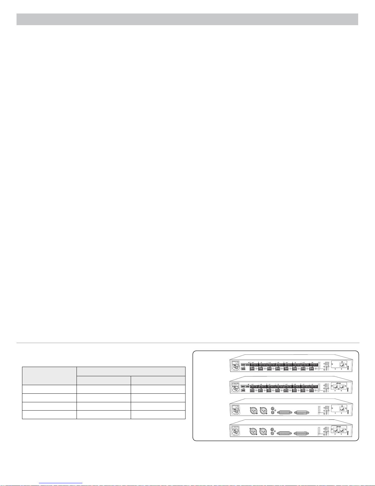
Model Variations
The following table describes the four SCM820 model variations:
Model
Connector Type Network Card
SCM820 Block Standard Ethernet
SCM820-DAN Block Dante Digital Audio
SCM820-DB25 DB25 Standard Ethernet
SCM820-DAN-DB25 DB25 Dante Digital Audio
Upgrading to Dante
A standard SCM820 can be upgraded with the Dante Network Interface Card
(A820-NIC-DAN) to add full digital audio networking capabilities. This replaces
the standard Ethernet port with two Dante network ports. This should only be
installed by qualified service personnel. Visit www.shure.com for more details.
2
Description
SCM820
SCM820-DAN
SCM820-DB25
SCM820-DAN-DB25
INTELLIMIX
AUX IN
OUT
+
+
+
+
+
+
R
L
mix a
+
mix b
OUT
mix a
+
mix b
gateINmute
ovrd
gnd
gateINmute
ovrd
gnd
gateINmute
ovrd
gnd
gateINmute
ovrd
+
+
8
direct out
direct out
AUX IN
+
+
R
L
gateINmute
gateINmute
ovrd
gnd
+
+
8
direct out
direct out
MIX OUTPUTS
MIX OUTPUTS
MIX A
MIX B
gnd
+
+
5
7
6
direct out
direct out
+
+
ovrd
gnd
gateINmute
ovrd
gnd
gateINmute
ovrd
gnd
+
+
5
7
6
direct out
direct out
AUX IN
INPUTS 1-8
L +R
SUM
AUX IN
INPUTS 1-8
L +R
SUM
+
gateINmute
ovrd
gnd
gateINmute
ovrd
gnd
gateINmute
+
direct out
+
gateINmute
+
direct out
ovrd
+
+
3
4
direct out
direct out
+
+
ovrd
gnd
gateINmute
ovrd
gnd
gateINmute
ovrd
+
+
3
4
direct out
direct out
DIRECT OUTPUTS 1-8
DIRECT OUTPUTS 1-8
CHANNEL
B
A
line
manual
+
gnd
gateINmute
ovrd
gnd
A
+0dB
mic
smooth
+30dB
mic
classic
+46dB
CH
B
extreme
+
custom
phm 48 VDC
lockout
dual mixer
2
1
direct out
INTELLIMIX
B
A
manual
+
gnd
gateINmute
ovrd
gnd
smooth
classic
extreme
+
custom
dual mixer
2
1
direct out
INTELLIMIX
B
A
manual
smooth
classic
extreme
custom
dual mixer
INTELLIMIX
B
A
manual
smooth
classic
extreme
custom
dual mixer
reset
auto link
CHANNEL
line
A
+0dB
mic
+30dB
mic
+46dB
CH
B
phm 48 VDC
auto link
CHANNEL
line
A
+0dB
mic
+30dB
mic
+46dB
CH
B
phm 48 VDC
auto link
CHANNEL
line
A
+0dB
mic
+30dB
mic
+46dB
CH
B
phm 48 VDC
auto link
00:0E:DD:AA:BB:CC
secondary
primary
lockout
reset
00:0E:DD:AA:BB:CC
lockout
reset
00:0E:DD:AA:BB:CC
secondary
primary
lockout
reset
00:0E:DD:AA:BB:CC

SCM820 Description
④
SCM820
1 2 3 4 5 6 7 8
gain
low cut
hi shelf
meter
push to solo | hold to mute
①
②
③ ⑦
Front Panel
① Channel Mode Selection
Press the button to select the function of the channel knobs and monitor
LED rings. See the Audio Signal Adjustment section for details on each
mode.
② Assignable Channel Knob
Adjusts settings and status for each input:
Rotate: Adjusts a setting.
Momentary Press: Solos the channel to the headphone output.
Press and Hold: Mutes the audio or bypasses the EQ setting.
③ Monitor LED Ring
13 LED segments display gain setting, input signal meter, IntelliMix gain
meter, channel solo, or EQ setting.
④ Channel Status LED
LED Channel Status
Off Channel is closed (attenuated in the automix).
Green Channel is open (selected in the automix).
Amber Channel EQ is bypassed.
Flicker Red
Solid Red Channel is muted.
⑤ Auxiliary Input Jack (1/8")
Unbalanced aux input sums left and right channels to mono. Front and
back panel aux inputs are summed to a mono signal and routed without
automixing to the mix outputs.
⑥ Master Output Knob
Adjusts settings and status of the mix outputs. See Front Panel Modes for
details.
Rotate:
Adjusts output gain or limiter threshold.
Momentary Press: Overrides a soloed channel to return the mix to the
headphone output.
Press and Hold: Mutes the audio or bypasses the limiter.
⑦ Master LED Ring
Displays gain setting or limiter threshold. A single LED represents each
mixer when they are both selected but set to different levels.
⑧ Master Mode Selection
Selects the function (gain or limiter) of the master knob and LED ring.
⑨ Mix Select Button
Selects Mix A, Mix B, or both for adjustment with the master knob and
monitoring on the LED ring and headphone output. Note: When both Mix
A and Mix B are selected, the headphone output only monitors Mix A.
Signal is clipping. Set the channel to a lower input
gain level.
⑤
AUX IN
L+R SUM
⑥
MASTER
⑨
limiter
gain
⑫
LIM
A B
A
0
-9
-18
-24
-36
-48
-60
⑧⑩⑪
⑬
®
IntelliMix
power
B
ethernet
network audio
automix link
dual mixer
lockout
⑭
HEADPHONE
⑮
⑩ Mix Status Indicator
LED Mix Status
Green
Mix is selected for adjustment and listening on the
headphone output.
Amber Limiter is bypassed.
Red Mix is muted.
⑪ Audio Output Meters
Monitor the output signal level and limiter threshold for mix A and B.
⑫
LIM (Limiter) LEDs
Illuminate amber when the audio levels exceed the limiter threshold.
⑬ System Status Indicators
The LEDs illuminate to indicate system settings:
LED Color Status
power Green Unit is powered on.
ethernet Green Unit is connected to a network.
All connected receive channels
Green
are OK (receiving digital audio as
expected).
One or more connected receive
channels experiencing a subscription
network audio
Flashing Green
error or is unresolved (transmitting
device is off, disconnected, renamed
or has incorrect network setting).
Red Clock synchronization problem.
No receive channels connected
(routing has not been established).
Two or more mixers are connected in
a link group.
automix link
Off
Green
Flashing Green Link Group is configuring.
Off Mixer is in standalone mode.
dual mixer
Green Mixer is set to Dual Mixer operation.
Off Mixer is set to Single Mixer operation.
Red Front panel controls are locked.
lockout
Flashing Red
An adjustment is attempted in lockout
mode.
⑭ Headphone Volume Knob
Adjust the volume of the headphone output.
⑮ Headphone Output Jack (1/4 in.)
Monitor a mix or a soloed channel.
3
①
+
②
①
②
③ ④ ⑦⑥
OUT
mix a
+
mix b
AUX IN
L
⑤
MIX A
gateINmute
MIX OUTPUTS
+
ovrd
gnd
+
8
direct out
gateINmute
MIX B
+
ovrd
gnd
gateINmute
ovrd
+
7
direct out
AUX IN
L +R
SUM
+
R
+
direct out
③
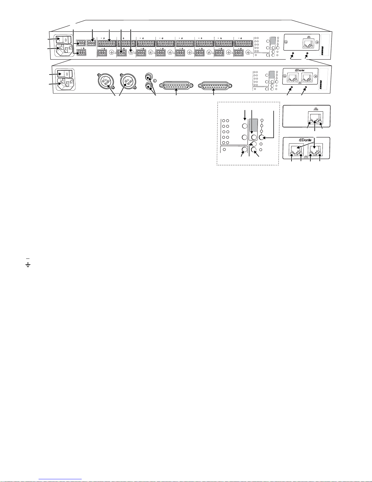
Rear Panel
① Power Switch
Turns the unit on or off.
② AC Power Jack
Supplies AC power to the mixer when plugged into a power source.
gnd
6
④
+
+
direct out
+
gateINmute
ovrd
gnd
+
5
direct out
INPUTS 1-8
⑤ ⑥
INTELLIMIX
CHANNEL
B
A
+
gateINmute
ovrd
gnd
+
4
direct out
+
gateINmute
ovrd
gnd
+
3
direct out
+
gateINmute
ovrd
gnd
+
2
direct out
manual
gateINmute
ovrd
gnd
smooth
classic
extreme
custom
dual mixer
1
line
A
+0dB
mic
+30dB
mic
+46dB
CH
B
phm 48 VDC
lockout
auto link
reset
00:0E:DD:AA:BB:CC
⑭ ⑮
INTELLIMIX
CHANNEL
B
DIRECT OUTPUTS 1-8
A
manual
smooth
classic
extreme
custom
dual mixer
line
A
+0dB
mic
+30dB
mic
+46dB
CH
B
phm 48 VDC
auto link
secondary
primary
lockout
reset
00:0E:DD:AA:BB:CC
⑭ ⑮
⑧
INTELLIMIX
B
A
manual
smooth
classic
extreme
custom
dual mixer
⑨
⑩
CHANNEL
A
B
⑫ ⑬
⑪
line
+0dB
mic
+30dB
mic
+46dB
CH
phm 48 VDC
auto link
⑰
secondary
⑱
⑰
⑰
⑯
primary
⑱
⑱
③ Mix A and Mix B Outputs
Active balanced outputs connect to amplifiers, DSP, mixer, or recording
device.
④ Auxiliary Input Jack
Unbalanced aux input sums left and right channels to mono. Front and
back panel aux inputs are summed to a mono signal and routed without
automixing to the mix outputs.
⑤ Channel Inputs 1–8
Active-balanced microphone- or line-level inputs.
Block Connectors
: Audio +
: Audio −
: Audio ground
gate: Logic gate out
mute: Logic mute in
ovrd: Logic override in
gnd: Logic ground
DB25 Connector
Pins: Audio plus, audio negative and audio ground. See Specifications
for details.
⑥ Direct Outputs 1–8
Each channel has a dedicated, impedance-balanced direct output on
the back panel that can be selected from one of five stages in the signal
path. See Configuring the Inputs and Outputs for details on direct output
routing.
⑦ Chassis Ground Screw 1–8
Provides an optional connection for microphone shield wire to chassis
ground.
⑧ IntelliMix Select Buttons
Scrolls through IntelliMix presets for each mix output. When
dual mixer is
off, the A button sets the mode for both Mix A and Mix B.
⑪ Input Gain Selection and LED Indicator
Sets the analog input gain level for the selected channel(s), illuminating
the green LED. All LEDs are off when the channel's audio source is set to
Network from the GUI.
⑫ Phantom Power Button and LED Indicator
Supplies 48 VDC phantom power to the selected channel(s), illuminating
the green LED. Phantom Power is disabled in the line (+0dB) gain setting.
⑬ Auto Link Button and LED Indicator
Enables networked SCM820-DAN mixers to automatically form a link
group. Link Groups enable a larger audio mix by incorporating inputs from
two or more mixers. See Link Groups for more details.
⑭ Lockout Button and LED Indicator
Hold for five seconds to disable front and back panel controls. The front
lockout LED illuminates red (flashing red during an adjustment
panel
attempt) and the back panel channel display shows L.
⑮ Reset Button
Press and hold for five seconds to reboot the mixer with default system
settings restored.
⑯ Network Ports
RJ-45 jacks for network connection.
⑰ Network Status LED (Green)
Off = no network link
On = network link established
Flashing = network link active
⑱ Network Speed LED (Amber)
SCM820:
Off = 10 Mbps
On = 100 Mbps
⑨ Dual Mixer Button
Sets the SCM820 as a dual mixer, indicated by the green LED.
⑩ Channel Select Button and Display
Press to select a single channel (1–8) or all channels (A) when changing
input gain or phantom power.
• When all channels are selected (A), Input Level and Phantom Power
LED indicators only illuminate if all channels have the same setting.
• L is displayed when the mixer is in lockout mode.
4
SCM820-DAN:
Off = 10/100 Mbps
On = 1 Gbps
gain
low cut
hi shelf
ch. meter
i
i
i
i
i
i
i
i
i
i
i
i
i
i
i
i
i
i
i
i
-∞ dB +18 dB
+0 dB
gain
low cut
hi shelf
ch. meter
i
i
i
i
i
i
i
i
i
i
i
i
i
i
i
i
i
i
i
i
gain
low cut
hi shelf
ch. meter
i
i
i
i
i
i
i
i
i
i
i
i
i
i
i
i
i
i
i
i
gain
low cut
hi shelf
ch. meter
i
i
i
i
i
i
i
i
i
i
i
i
i
i
i
i
i
i
i
i
gain
low cut
hi shelf
ch. meter
i
i
i
i
i
i
i
i
i
i
i
i
i
i
i
i
i
i
i
i
320 Hz25 Hz
92 Hz
-60 dBFS 0 dBFS
-∞ dB +18 dB
+0 dB
+12 dB-12 dB
+0 dB
-16 dBFS
gain
low cut
hi shelf
ch. meter
i
i
i
i
i
i
i
i
i
i
i
i
i
i
i
i
i
i
i
i
gain
low cut
hi shelf
ch. meter
i
i
i
i
i
i
i
i
i
i
i
i
i
i
i
i
i
i
i
i
gain
low cut
hi shelf
ch. meter
i
i
i
i
i
i
i
i
i
i
i
i
i
i
i
i
i
i
i
i
gain
low cut
hi shelf
ch. meter
i
i
i
i
i
i
i
i
i
i
i
i
i
i
i
i
i
i
i
i
320 Hz25 Hz
92 Hz
-60 dBFS 0 dBFS
-∞ dB +18 dB
+0 dB
+12 dB-12 dB
+0 dB
-16 dBFS
gain
low cut
hi shelf
ch. meter
i
i
i
i
i
i
i
i
i
i
i
i
i
i
i
i
i
i
i
i
i
i
i
i
i
i
i
i
i
i
i
i
i
i
i
i
i
i
i
i
-80 dB 0 dB
-15 dB
gain
low cut
hi shelf
ch. meter
i
i
i
i
i
i
i
i
i
i
i
i
i
i
i
i
i
i
i
i
gain
low cut
hi shelf
ch. meter
i
i
i
i
i
i
i
i
i
i
i
i
i
i
i
i
i
i
i
i
gain
low cut
hi shelf
ch. meter
i
i
i
i
i
i
i
i
i
i
i
i
i
i
i
i
i
i
i
i
320 Hz25 Hz
92 Hz
-∞ dB +18 dB
+0 dB
+12 dB-12 dB
+0 dB
gain
low cut
hi shelf
ch. meter
i
i
i
i
i
i
i
i
i
i
i
i
i
i
i
i
i
i
i
i
gain
low cut
hi shelf
ch. meter
i
i
i
i
i
i
i
i
i
i
i
i
i
i
i
i
i
i
i
i
320 Hz25 Hz
92 Hz
-∞ dB +18 dB
+0 dB
gain
low cut
hi shelf
i
i
i
i
i
i
i
i
i
i
i
i
i
i
i
i
i
i
i
i
gain
low cut
hi shelf
i
i
i
i
i
i
i
i
i
i
i
i
i
i
i
i
i
i
i
i
gain
low cut
hi shelf
i
i
i
i
i
i
i
i
i
i
i
i
i
i
i
i
i
i
i
i
gain
low cut
hi shelf
i
i
i
i
i
i
i
i
i
i
i
i
i
i
i
i
i
i
i
i
i
i
i
i
i
i
i
i
i
i
i
i
i
i
i
i
i
i
i
i
320 Hz25 Hz
92 Hz
-2 dBFS-50 dBFS
-24 dBFS
-60 dBFS 0 dBFS
-∞ dB +18 dB
-∞ dB +18 dB
+0 dB
+0 dB
+12 dB-12 dB
+0 dB
MASTER
gain
A B
limiter
i
i
i
i
i
i
i
i
i
i
i
i
i
i
i
i
i
i
i
i
MASTER
gain
A B
limiter
-16 dBFS
gain
low cut
hi shelf
i
i
i
i
i
i
i
i
i
i
i
i
i
i
i
i
i
i
i
i
i
i
i
i
i
i
i
i
i
i
i
i
i
i
i
i
i
i
i
i
-80 dB 0 dB
-15 dB
gain
i
i
i
i
i
i
i
i
i
i
i
i
i
i
i
i
i
i
i
i
gain
i
i
i
i
i
i
i
i
i
i
i
i
i
i
i
i
i
i
i
i
gain
i
i
i
i
i
i
i
i
i
i
i
i
i
i
i
i
i
i
i
i
gain
i
i
i
i
i
i
i
i
i
i
i
i
i
i
i
i
i
i
i
i
i
i
i
i
i
i
i
i
i
i
i
i
i
i
i
i
i
i
i
i
320 Hz25 Hz
92 Hz
-60 dBFS 0 dBFS
-∞ dB +18 dB
-∞ dB +18 dB
+0 dB
+0 dB
+12 dB-12 dB
+0 dB
MASTER
gain
A B
limiter
-16 dBFS
gain
i
i
i
i
i
i
i
i
i
i
i
i
i
i
i
i
i
i
i
i
i
i
i
i
i
i
i
i
i
i
i
i
i
i
i
i
i
i
i
i
-80 dB 0 dB
-15 dB
Operating the Mixer
AUX IN
MASTER
lockout
power
ethernet
network audio
automix link
dual mixer
LIM
A
B
-9
-18
-24
-36
-48
-60
0
gain
limiter
L+R SUM
gain
low cut
hi shelf
meter
push to solo | hold to mute
1234567
8
A
B
HEADPHONE
IntelliMix®
SCM820
gain
low cut
hi shelf
meter
push to solo | hold to mute
1 2 3 4 5
IntelliMix®
MASTER
LIM
A
-9
-18
-24
-36
-48
-60
0
gain
limiter
A B
lockout
power
ethernet
network audio
automix link
dual mixer
HEADPHONE
SCM820
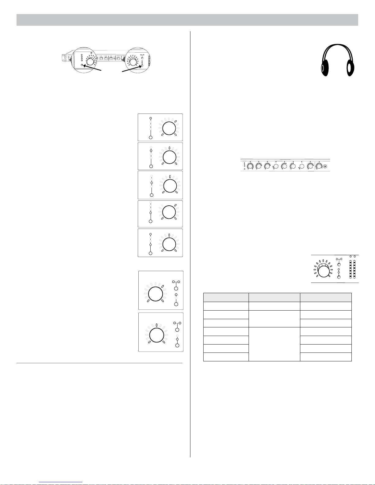
Front Panel Modes
For Channels 1-8
and Aux
Channel Inputs
The channel knobs operate in five modes for different types of input signal
adjustment and display. Use the front panel mode selection button to select
from the following modes.
Channel Gain (gain)
Adjust gain within a 128 dB range while displaying
the gain setting on the LED ring. Unity gain is at the
9th LED.
Low Cut (
Adjust the frequency of the low cut filter (6 dB/octave
from 25 to 320 Hz). Use to remove low-frequency
noise such as table vibrations or air-conditioning
rumble.
High Shelf (
Adjust the high shelf boost or cut (± 12 dB at 5
kHz). Use to add presence to muddy vocals, temper
sibilant vocals, or enhance the sound of off-axis
lavalier microphones.
Input Signal Meter (
LEDs display the input signal level in real-time.
Channel gain is adjustable in this mode, and will
momentarily display channel gain setting during
adjustments.
IntelliMix Gain Meter (
LEDs display the IntelliMix attenuation applied
in realtime. Channel gain is adjustable in this
mode, displaying the setting on the LEDs during
adjustments.
Mix Outputs
The mix output knob operates in two modes to control
the mix output. Use the master function button to select
one of two modes.
Output Gain (gain)
Rotate to adjust the output gain of the selected mix.
The output signal level is displayed on the meters.
Limiter Threshold (
Rotate to adjust the limiter threshold of the mix (−2
to −50 dBFS). The limiter threshold level is displayed
on the meters.
Audio Mute and Bypass
Mute Channel Input
Press and hold the input channel knob while in gain or ch. meter mode. The
channel status LED turns red.
Mute Mix Output
Press and hold the
turns red.
Bypass Input EQ
Press and hold the input channel knob while in
channel status LED turns amber.
Bypass Output Limiter
Press and hold the
LED turns amber.
low cut)
hi shelf)
ch. meter)
gain and ch. meter)
limiter)
MASTER knob while in gain mode. The mix status LED
MASTER knob while in limiter mode. The mix status
Mode
Selector
low cut or hi shelf mode. The
For Mix
Outputs
Monitoring
Headphone Output
Use the front panel headphone jack for monitoring
audio. By default, the headphones monitor the mix prefader/post-EQ (change to post-fader/post-limiter from
GUI > Preferences Tab).
Solo to Headphones
A channel can be soloed to the headphone jack.
Solo Channel: Press a channel knob to solo that channel to the
headphones. The other LED rings dim to highlight the soloed channel.
Exit Solo: Press the soloed channel knob or press the
return the mix to the headphones.
Input Meters
The front panel channel meters can be set to display real-time signal
information. Use the front panel mode selection button to scroll to the
desired mode:
IntelliMix®
1 2 3 4 5 6 7 8
gain
low cut
hi shelf
meter
Input Signal Level
The channel meter mode (
ch. meter) displays real-time audio input signal
level for each channel.
IntelliMix Gain
The IntelliMix meter mode (
gain and ch. meter illuminated) displays
IntelliMix gain operation in real-time across the channel LEDs. Channels
that gate open will display more gain than channels that are closed
(attenuated) in the mix.
Output Meters
The output meters indicate the level of each mix
before the digital-to-analog conversion. By default,
the meter displays average and peak audio levels.
It is good practice to use −18 dBFS on the SCM820
meter as an approximation of 0 VU on an analog
meter.
LED Description Signal Level (dBFS)
Red (7) Clip 0 to -6
Yellow (6)
Yellow (5) -9 to -18
Normal peaks
Green (4)
Green (3) -24 to -36
Green (2) -36 to -48
Signal Present
Green (1) -48 to -60
Changing the Metering Type
Go to the Preferences tab of the GUI to change the following metering
options:
• Meter Type: Change the input and output meters from displaying VU +
Peak (default) to VU or Peak.
• IntelliMix Gain Metering: The Input tab of the GUI can display input
signal level (default) or IntelliMix gain metering in realtime.
MASTER
-6 to -9
-18 to -24
Master knob to
AUX IN
L+R SUM
LIM
A B
-18
-24
gain
-36
limiter
-48
-60
0
-9
A
B
5
The SCM820 Graphical User Interface
reset
primary
00:0E:DD:AA:BB:CC
SCM820-Dan-ffeee5.local 192.168.200.22
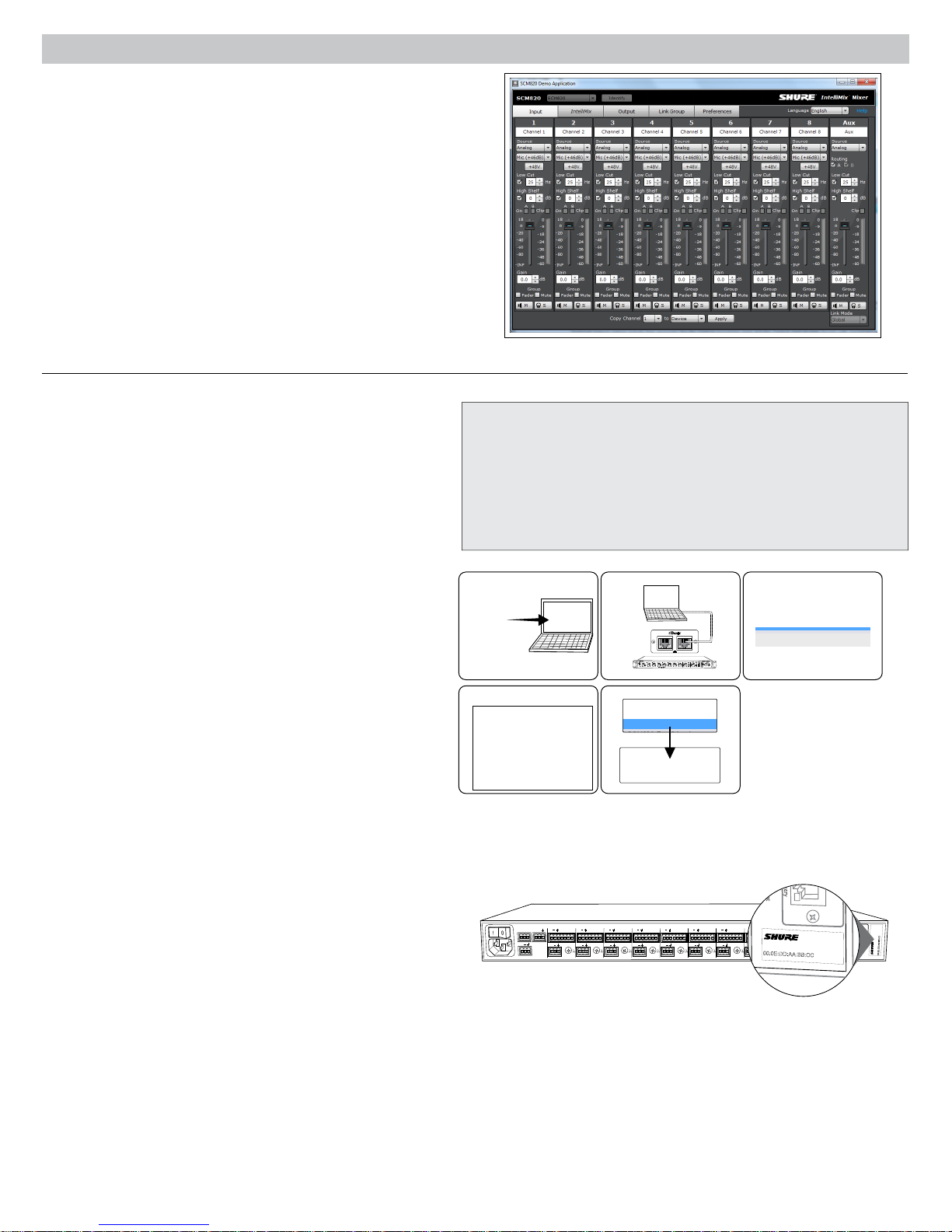
Graphical User Interface (GUI)
The SCM820 graphical user interface (GUI) enables comprehensive
control of the mixer from a web browser. The GUI is hosted from a
webserver embedded on the SCM820, and is accessible from any
computer on the network. Use the GUI for the following functions:
• Manage mixers from a remote location.
• Customize IntelliMix parameters.
• Form large automixes with custom link groups.
• Assign the direct outputs in the signal path.
• Configure Redundant or Split networks.
Accessing the GUI
The Shure Web Server Discovery application finds all Shure devices on
the network that feature a web-based GUI. Follow these steps to install
the software and access the SCM820 GUI:
① Install the Shure Discovery application
Load the Shure USB drive and install the application. This
automatically installs the required Bonjour device discovery tool on
the computer. This application is also available from www.shure.com.
System Requirements
• Windows: Windows XP (32 and 64 bit), Windows Vista and Windows 7
• Apple: Mac OSX 10.6.0 and higher
• Latest version of Adobe Flash Player
• Bonjour software (bundled with the Shure Discovery app)
• The GUI is supported on the following web-browsers: Internet Explorer,
Firefox, Safari and Chrome.
② Connect the network
Ensure the computer and the mixer are on the same network.
③ Launch the Discovery application
The app displays all Shure devices that feature a GUI.
④ Open the SCM820 GUI
Double-click on a device to open its GUI in a web browser.
⑤ Bookmark the GUI (recommended)
Bookmark the device's DNS name to access the GUI without the
Shure Discovery app.
Accessing the GUI without the Discovery App
If the Discovery application is not installed, the SCM820 GUI can be
accessed by typing the DNS name into an internet browser. The DNS
name is derived from model of the unit (SCM820 or SCM820-DAN), in
combination with the last three bytes (six digits) of the MAC address,
and ending in .local.
Format Example: If the MAC address of a unit is 00:0E:DD:AA:BB:CC,
then the link is written as follows:
• SCM820-DAN: http://SCM820-DAN-aabbcc.local
• SCM820: http://SCM820-aabbcc.local
① ② ③
secondary primary
IntelliMix®
1 2 3 4 5 6 7 8
gain
w cut
o
l
hi shelf
er
t
me
push to solo | hold to mute
SCM820
LIM
MASTER
A
B
er
w
o
p
A
B
A
UX IN
HEADPHONE
0
net
ether
-
9
k audio
r
o
w
t
ne
-1
8
omix link
t
au
-2
4
gain
er
x
dual mi
-3
6
limi
t
er
-4
8
L+R SUM
-6
0
lockout
④ ⑤
OUT
AUX IN
+
+
R
L
mix a
+
+
mix b
direct out
+
+
+
+
+
gateINmute
ovrd
gnd
gateINmute
ovrd
gnd
gateINmute
ovrd
gnd
gateINmute
ovrd
gnd
gateINmute
ovrd
+
+
+
7
8
direct out
6
direct out
direct out
gnd
+
+
5
4
direct out
direct out
+
gateINmute
ovrd
gnd
gateINmute
ovrd
gnd
+
+
3
2
direct out
direct out
SCM820-DAN SCM820-Dan-ffeee5.local 192.168.200.22
ROOM 5
CONFERENCE
SCM820
SCM820-ffaaa2.local
192.168.200.23
INTELLIMIX
CHANNEL
B
A
line
manual
A
gateINmute
ovrd
gnd
+0dB
mic
smooth
+30dB
mic
classic
CH
+46dB
B
extreme
secondary
custom
phm 48 VDC
IntelliMix
dual mixer
direct out
1
Dante
primary
lockout
reset
00:0E:DD:AA:BB:CC
6
Inputs 1-8
Aux In
L + R
SUM
Inputs 1-8
+
+
+
+
+
+
+
+
6
4
5
3
2
1
+
+
1
+
+
+
+
+
+
+
+
+
+
+
+
+
+
6
4
5
3
2
1
7
8
+
Inputs 1-8
Aux In
MIX OUTPUTS
MIX A
MIX B
L + R
SUM
Inputs 1-8
Aux In
MIX B
L + R
SUM
+
+
+
+
+
+
6
7
8
+
MASTER
lockout
p
o
w
er
ethe
r
net
ne
t
w
o
r
k audio
aut
omix link
dual mi
x
er
LIM
A
B
-
9
-1
8
-2
4
-3
6
-4
8
-6
0
0
gain
limi
t
er
7
8
A
B
HEADPHONE
AUX IN
L+R SUM
Installation
Direct Outputs 1-8
+
+
+
+
+
+
+
+
+
+
6
4
5
3
2
1
+
+
1
7
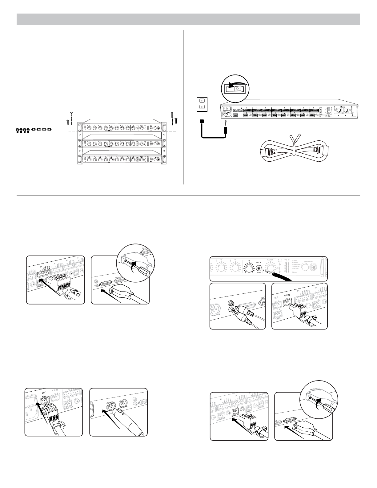
Rackmounting
Rackmount the mixer using the screws and washers supplied in the
Hardware Kit. Follow these general best practices when rackmounting
equipment:
• Ambient temperature of the rack should not exceed specified operating
temperature range of the device.
• Keep fan inlet and side air vents clear from obstructions and provide
adequate space for airflow within the rack.
• When possible, provide 1 RU of empty space between each device.
LIM
MASTER
A
B
er
w
o
p
A
1 2 3 4 5 6 7 8
gain
w cut
o
l
hi shelf
er
t
me
gain
w cut
o
l
hi shelf
er
t
me
gain
w cut
o
l
hi shelf
er
t
me
push to solo | hold to mute
1 2 3 4 5 6 7 8
push to solo | hold to mute
1 2 3 4 5 6 7 8
push to solo | hold to mute
B
A
UX IN
HEADPHONE
0
net
r
ethe
-
9
k audio
r
o
w
t
ne
-1
8
omix link
t
au
-2
4
gain
er
x
dual mi
-3
6
limi
t
er
-4
8
L+R SUM
-6
0
lockout
LIM
MASTER
A
B
er
w
o
p
A
B
A
UX IN
HEADPHONE
0
net
r
ethe
-
9
k audio
r
o
w
t
ne
-1
8
omix link
t
au
-2
4
gain
er
x
dual mi
-3
6
limi
t
er
-4
8
L+R SUM
-6
0
lockout
LIM
MASTER
A
B
er
w
o
p
A
B
A
UX IN
HEADPHONE
0
net
r
ethe
-
9
k audio
r
o
w
t
ne
-1
8
omix link
t
au
-2
4
gain
er
x
dual mi
-3
6
limi
t
er
-4
8
L+R SUM
-6
0
lockout
Typical Audio Connections
Power
Connect the unit to AC power using the supplied IEC cable. Turn on the
power switch.
INTELLIMIX
OUT
AUX IN
+
+
R
L
mix a
+
mix b
direct out
+
+
+
+
gateINmute
ovrd
gnd
gateINmute
ovrd
gnd
gateINmute
ovrd
gnd
gateINmute
ovrd
+
+
7
8
direct out
gnd
+
+
+
5
6
direct out
direct out
direct out
+
gateINmute
ovrd
gnd
gateINmute
ovrd
gnd
gateINmute
ovrd
gnd
+
+
3
4
2
direct out
direct out
CHANNEL
B
A
line
manual
+
gateINmute
ovrd
gnd
A
+0dB
mic
smooth
+30dB
mic
classic
+46dB
CH
B
extreme
+
1
direct out
secondary
custom
dual mixer
primary
phm 48 VDC
lockout
auto link
reset
00:0E:DD:AA:BB:CC
① Channel Inputs
• Microphones
• Insert send from a mixer
• Dante network audio
③ Mix Outputs
• Amplifier
• Powered speakers
• Mixer channel inputs
② Aux Inputs
Aux-level sound sources:
• MP3 player
• Computer headphone output
• CD player
④ Direct Outputs
• Insert returns to a mixer
• Recording device
• Mixer channel inputs
7

Configuring the Inputs and Outputs
Unless where noted, configurations can be made from the hardware or from the GUI.
Inputs
① Select the Audio Source (GUI only)
• Analog (default): Audio is from a microphone or line-level audio source
connected to a channel input on the mixer back panel.
• Network: Audio is from the Dante digital audio network. Go to the Inputs
tab of the GUI to select Network audio for each desired channel. Dante
Controller software is required to properly route audio to the channel
inputs.
② Select the Input Gain
Select the analog input gain for each channel. No gain is applied for
analog line-level or when the audio source is set to Network.
• Mic (+46dB): For less sensitive microphones, such as dynamics.
• Mic (+26dB): For loud talkers or sensitive microphones such as
condensers.
• Line (+0dB): For line-level sources such as mixer inserts.
③ Supply Phantom Power
Supply 48 V phantom power to the channel when using condenser
microphones. (Phantom power is disabled when Input gain is set to Line.)
④ Adjust Channel EQ
Adjust the high- and low-frequency equalization to improve intelligibility
and reduce undesired noise:
• Low Cut: Ideal for attenuating low-frequency vibration caused by table
vibrations or air-conditioning rumble. Adjust the frequency of the 12 dB/
octave filter from 25 - 320 Hz.
• High Shelf: For tempering sibilant speech or enhancing the sound of offaxis microphones. Use this to boost or cut the signal by 12 dB at 5 kHz
with a slop of 12dB/octave.
Direct and Mix Outputs
⑤ Assign the Direct Outputs (GUI Only)
Assign the Direct Output for each channel from the Output tab of the
GUI.
• Pre-EQ: After the Input Gain
• Post-EQ: After the EQ blocks
• Post-Fader: After the channel fader
• IntelliMix: After the IntelliMix gating decision
• IntelliMix NOMA: After IntelliMix gating and NOMA decisions
⑥ Set Mix Output Level (GUI Only)
Set the Output level according to the input of the connecting equipment:
• Line (-0) (default): No attenuation to the output level.
• Aux (-20): The signal is attenuated 20 dB to avoid clipping a line input.
• Mic (-46): The signal is attenuated 46 dB to match a microphone input.
⑦ Set the Limiter
The output limiter prevents distortion during loud program peaks without
affecting normal program levels. This prevents overloading the devices
connected to the mixer outputs.
⑧ Adjust the Output Gain
Adjust the overall output level of the mix.
Auxiliary (Aux) Input
The SCM820 features two auxiliary inputs: an 1/8” jack on the front panel
and a back panel input (block connector or RCA connectors, depending
on the model). Each input sums the left and right channel to a mono
signal. This mono signal is routed directly to the mix outputs, bypassing
the automixing process. Use this input for sources such as an MP3
player or computer speaker output.
Digital Channels
When the mixer is connected to a Dante network, the left and right
channels are accessible before they sum to the mono signal for the mix
outputs. Use the Aux L and Aux R channels in Dante Controller to route
audio to and from the aux channel.
8
 Loading...