

MODEL RMSOOE
CUSTOM MAGNETIC
CARTRIDGE
HIGH TRACKABILITY
ELLIPTICAL STYLUS
WITH
DATA SHEET

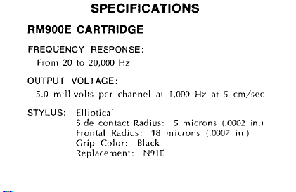
SPECIFICATIONS
RMSOOE CARTRIDGE
FREQUENCY RESPONSE:
From
20
to
20,000
Hz
OUTPUT VOLTAGE:
5.0
mlll~volts per channel at
STYLUS: Elliptical
S~de contact Radius.
Frontal Radius:
Grip Color: Black
Renlacement:
18
N91E
1,000
5
microns
microns
Hz
at 5 cm/sec
LO007
(.0002
In
)
In.)
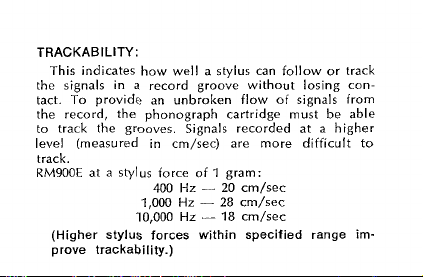
TRACKABILITY:
This indicates how well a stylus can follow or track
the signals in
tact. To provide an unbroken flow of signals
the record, the phonograph cartridge must be able
to
track the gmoves. Signals recorded at a higher
level (measured in
track.
RM900E at a stylus force of 1 gram:
(Higher stylus forces within specified range
prove trackability.)
a
record groove without losing con-
cm/sec) are more difficult
-
Hz
20 cm/sec
-
18
cm/sec
400 Hz
1,000 Hz - 28 cm/sec
10,000
from
im-
to
V
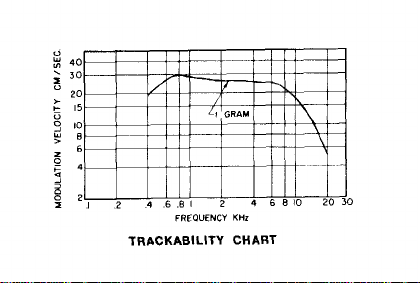
1
'
I,
0
2
Y
z
p
3
40
30
20
15
10
4
FREQUENCY
TRACKABILITY
KHz
CHART
0

TRACKING FORCE RANGE:
3/4 to
1-1/2
Th~s is the amount of force required of the stylus
tip to properly play a record. The lighter the trackfing force, the longer the life of the stylus and
records,
OPTIMUM LOAD:
47,000 ohms resistance in parallel with 400 to 500
picofarads total capacitance per channel. Load
\islance can be up to 70,000 ohms with almost no
audible
tance includes
plif~er input circuit.
grams
prov~ded that tracking is
change in frequency response. Total capaci-
both the tone arm wiring and am-
maintained.
re-

CHANNEL SEPARATION
25
dB
at
1,000
Hz
INDUCTANCE:
720
millihenries
D.C. RESISTANCE:
630
ohms
MOUNTING:
mm
12.7
(standard
1/2
(minimum):
in.) mounting centers

WEIGHT:
6
grams
TERMINALS:
4
terrn~nals
OPERATION:
Thr
RM900E
hern developed for use w~th all h~gh i~delity am-
pl~i~crr havlng magnetic and constant velocity inputs. Recommended
grams for optimum results. Forrrr greater than
1-1/2
Dynet~c phonograph cartr~dge\ have
nerdle force ir
grams should not
be
uscd.
3/4
to
1-1/2

Mounting
The
RM900E
ard
w~th each cartr~dge for mountlng purposes. In some
tone arms and
deep that the stylus cannot he conveniently
plated. For these
Insure adequate clearance for stylus removal.
to
For optimum vertical tracking angle, the cartridge
should be mounted to the top
block is parallel to the record playing
Dynetlc Cartridge has
1/2
in ) mountlng centers. Hardware
plug-ln shells, the carlrldge sit5
applications,
12
7
mm (stand-
18
supplied
spacers are provided
of
the mounting
wrface.
rp-
ro

Connections
4-LEAD
STEREO CONNECTION:
of right channel to terminal
ground lead of right channel to terminal
Connect "hot" lead of left channel to terminal
and shield or ground lead of left channel to
To prevent "ground loops" and hum, no common
connection should
MONOPHONIC OPERATION:
back of recordings, the left and
should be connected in parallel. This is accomplished most conveniently by setting the function
switch on the associated amplifier to
"MONO."
be
Connect "hot" lead
"K"
and shield or
"RG."
"LC."
used at cartridge terminals.
For monophonic play-
right
channels
"A+B"
"L"
or

CAUTION:
tridge terminals. Make all solder connections to
terminal jacks provided before
the terminals.
Do not make solder connections to car-
slipptng them over
RIGHT
CMAMXEL
RIGHT
CSIHNEI
GROUWD CRWNDSD
TO
CASE1
TERMINAL DIAGRAM STYLUS REPLACEMENT
FIGURE
I
FIGURE
2

Recommended
Use a camel's hair brush (No. 2 size or smaller),
trimmed to approximately
in alcohol or an alcohol-distilled water solution.
Commercial cleaning solutions may cause stylus
damage or corrosion. The alcohol will remove any
sludge deposit coating the stylus tip. Always brush
stylus from back to front; never brush or wipe
from front to back or side to side.
Stylus
Cleaning
6
mm
(1/4
in.), dipped

Easy
Stylus
Grasp molded hous~ng oi stylus between thumb
Replacement
forcl~nger. Gently w~thdraw stylus by pulling
and
iorward out of cartridge. Grasp
thumb and loref~nger and ~nsrrl Into stylus
between
socket. Press stylus
housing of the stylus mates with the cartridge
case. Care must be taken not
sl~p off the molded housing of the stylus, re-
to
sult~ng in damage to the stylus t~p or shank.
(see Figure
replaremer~t stylus
Into socket until the molded
ro
allow the finger
2)

SPECIAL
NOTE:
in these cartridges is the most critical component.
To maintain the original performance standards of
your cartridge, be certain that any replacement
stylus you buy bears the following certification on
the package: "This Stereo
sion manufactured by Shure Brothers Inc."
The Dynetic stylus assembly used
Dynetic@ stylus is preci-

retaln proof of purchase dare. This guarantee
includes all parts and labor. Th~s guarantee
doer
no( include stylur wear.
SHIPPING INSTRUCTIONS: Carefully repack
the unit and return
If outs~de the Unitcd States, return the unlt
to your dealer or authorized Shure Service
Center for repair. The
lo
vou nre~aid.
~t prcpa~d io the factory.
un~t will
be
returned

PATENT NOTICE:
under one or
3,055,100, 3,077,521, 1,077,522
Cartridge and stylus manufactured
more of the follow~ng
and
U
1,461,889.
Available exclusively through
ROYAL ELECTRONIC DIST.
Manufactured by Shure Brothers Incorporated
222
Hartrey Avenue, Evanston,
11
60204
S
Patents
COPYRIGHT
27A947
(NE)
1972.
SHURE BROTHERS
PRINTED IN
INC.
U.
S.
A.
 Loading...