

REPLACEMENT DYNAMIC CARTRIDGE
METAL STRIP
Model R50 User Guide
The Model R50 is a direct cartridge replacement for the
following microphone models:
540, 540S, and 540SH
550S
560
561
574SA, 574SB
575S, 575SB
579SB
Included with the dynamic cartridge are a rubber gasket and
a metal strip.
INSTALLATION AND CONNECTIONS
Use the following instructions to replace the dynamic
cartridge. Be sure to refer to the proper model number.
NOTE: Do not solder leads to taped areas of terminal
board.
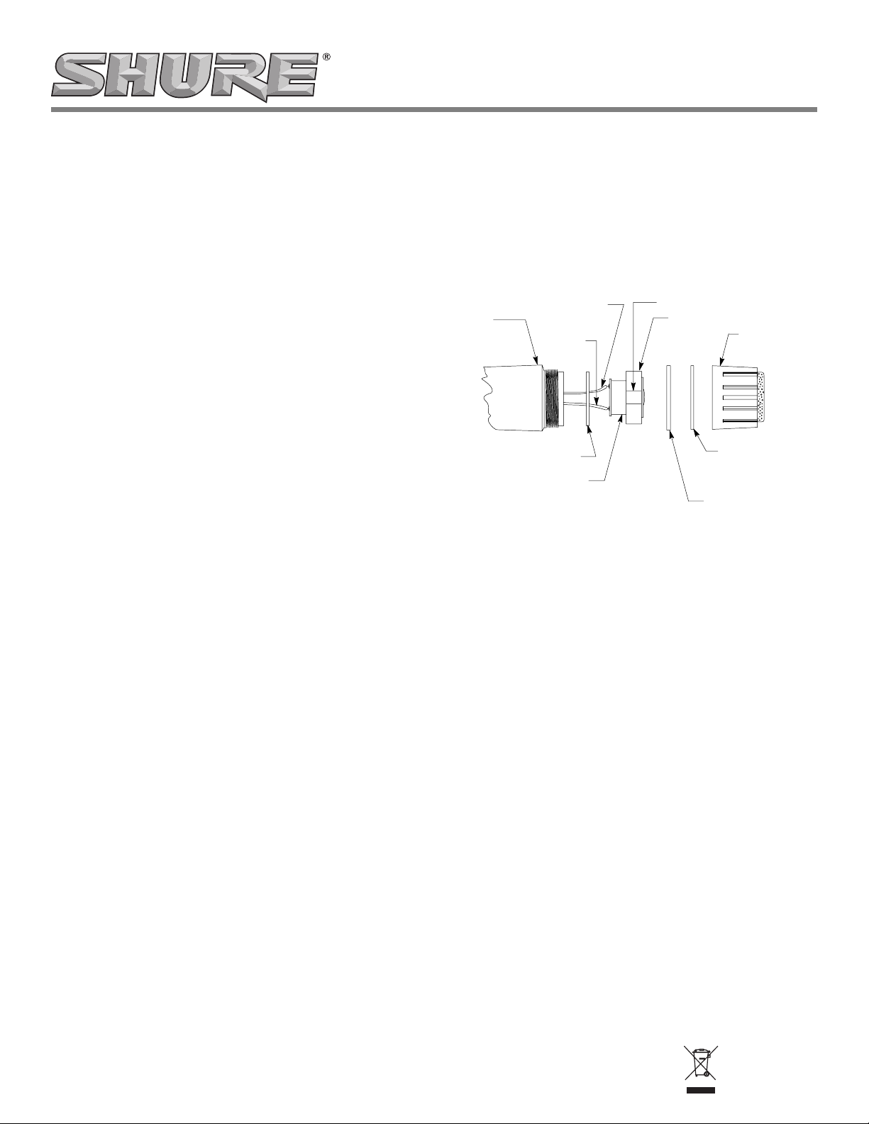
Models 540, 540S, and 540SH Microphones
1. Holding microphone in vertical position, unscrew (turn
counterclockwise) and remove microphone grille-cap
assembly, perforated aluminum plate, and steel spacer.
2. Gently remove cartridge with rubber gasket from case.
3. Disconnect leads from old cartridge.
4. Wrap metal strip around new rubber gasket (See Figure 1).
Install new rubber gasket on new cartridge and connect
leads to replacement cartridge. Microphone case must
connect to cartridge frame through metal strip. Note lead
color and terminal coding as in Figure 1.
MICROPHONE
CASE
STEEL ADAPTER WASHER
YELLOW
(TO ”+” TERMINAL)
GREEN
CARTRIDGE
RUBBER GASKET
MODELS 540, 540S AND 540SH
FIGURE 1
GRILLE-CAP
ASSEMBLY
ALUMINUM PLATE
5. Assemble cartridge into case making sure it is properly
seated in steel adapter washer.
6. Reassemble steel spacer, aluminum plate, and capgrille assembly. Make sure cap is tightened securely.
©2005, Shure Incorporated
27C605 (Rev. 5)
Printed in U.S.A.
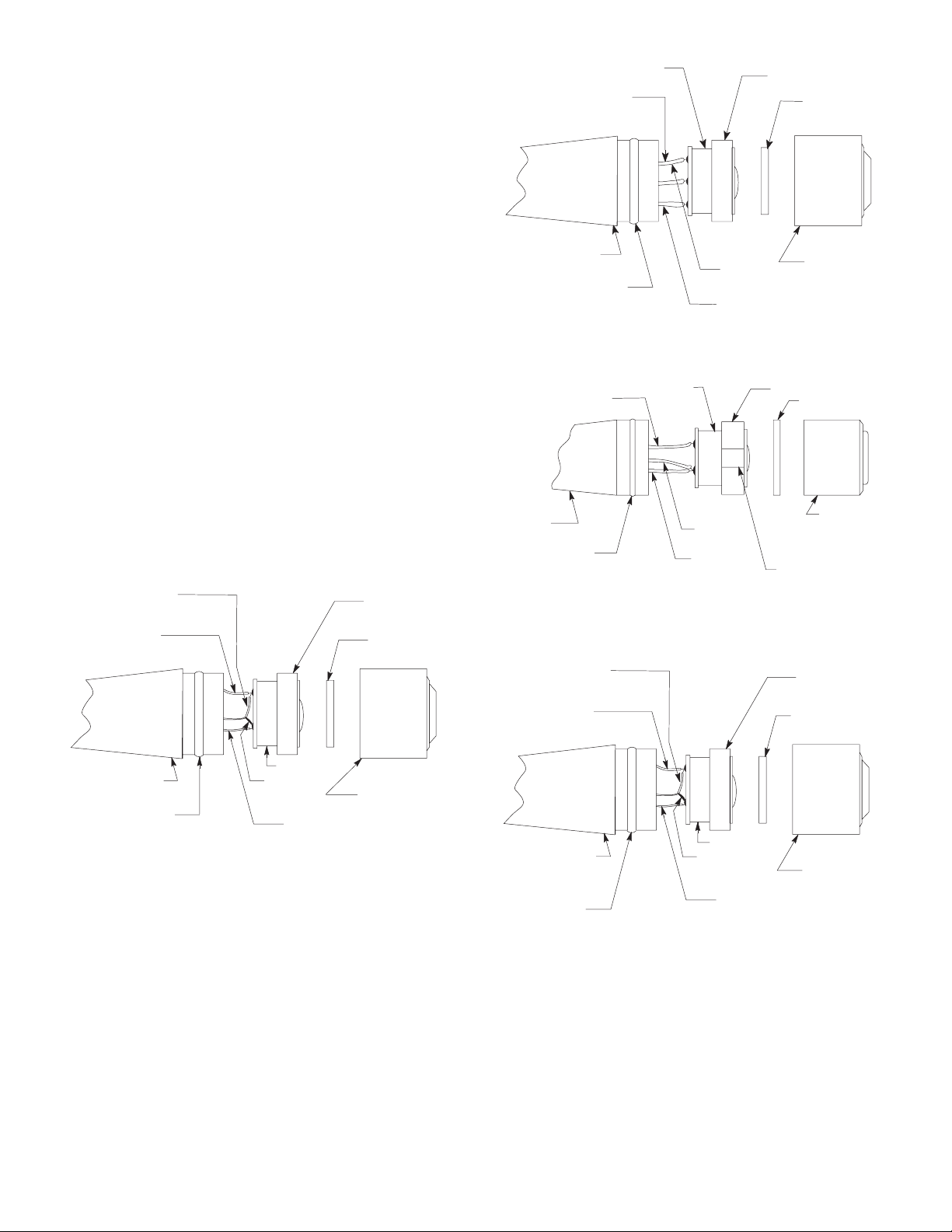
Models 574SA, 574SB, 575S, and 575SB Microphones
1. Hold case of microphone firmly and remove microphone
cap-grille assembly by pulling hard to separate cap from
case. See Figure 2 for 574SA, Figure 3 for 574SB,
Figure 4 for 575S, and Figure 5 for 575SB.
2. Remove foam bushing if it did not come off with cap.
3. Gently remove cartridge with rubber gasket from case.
4. Disconnect leads from old cartridge.
5. For 574SB and 575SB install new rubber gasket on new
cartridge and connect leads to replacement cartridge.
Note lead color and terminal coding in Figure 3 for
574SB, and Figure 5 for 575SB.
6. For 574SA and 575S (when original cartridge contains
metal strip), wrap metal strip around new rubber gasket
(see Figures 2 and 4).
NOTE: Certain Model 575S microphones do not contain
metal strips; if none is present on original cartridge, discard
metal strip supplied with new cartridge. Install new rubber
gasket on new cartridge and connect leads. Internal shield
of microphone must connect to cartridge frame through
metal strip (when metal strip is used). Note lead color and
terminal coding as in Figures 2 and 4.
7. Assemble cartridge into case, making sure it is properly
seated. Reassemble foam bushing and cap-grille assembly to microphone case. Make sure cap is securely seated
and held by internal snap ring.
WHITE
(TO ”+” TERMINAL)
RED
(TO ”+” TERMINAL)
RUBBER GASKET
FOAM BUSHING
BLACK
MICROPHONE CASE
SNAP RING
GREEN
(TO ”+” TERMINAL)
MICROPHONE
CASE
SNAP RING
WHITE
(TO ”+” TERMINAL)
CARTRIDGE
MODEL 574SB
CARTRIDGE
RED (TO ”+” TERMINAL)
FIGURE 3
YELLOW
WHITE
MODEL 575S
FIGURE 4
WHITE
RUBBER GASKET
FOAM BUSHING
GRILLE-CAP
ASSEMBLY
RUBBER GASKET
FOAM BUSHING
GRILLE-CAP
ASSEMBLY
METAL
STRIP
(SEE STEP 6)
RUBBER GASKET
MICROPHONE
CASE
SNAP RING
CARTRIDGE
SHIELD
BLACK
MODEL 574SA
FIGURE 2
GRILLE-CAP
ASSEMBLY
RED
(TO ”+” TERMINAL)
MICROPHONE
CASE
SNAP RING
FOAM BUSHING
CARTRIDGE
SHIELD
GRILLE-CAP
ASSEMBLY
BLACK
MODEL 575SB
FIGURE 5
2

Model 560 Microphones
1. Hold case of microphone firmly and remove grille-cap
assembly by pulling hard to separate cap from case.
2. Remove foam bushings, aluminum plate, and aluminum
washer. See Figure 6. (These parts may remain in cap.
If so, leave parts in cap.)
3. Remove cartridge from rubber gasket by peeling back
edge of rubber gasket. DO NOT remove rubber gasket
from case.
4. Disconnect leads from old cartridge.
5. Connect leads to new cartridge. Note lead color and terminal coding in Figure 6.
6. Seat cartridge into rubber gasket. Reassemble aluminum washer, aluminum plate, foam bushings, and grillecap assembly to microphone case. Make sure cap is
securely seated and held by internal snap ring.
Model 561 Microphones
1. Turn 4-40 set screw (clockwise) with Allen wrench and then
remove microphone grille-cap assembly. (See Figure 7.)
2. Remove foam bushings, aluminum plate, and aluminum
washer. (These parts may remain in cap. If so, leave
parts in cap.)
3. Disconnect leads from old cartridge.
4. Install new rubber gasket on new cartridge and connect
leads. Note lead color and terminal coding in Figure 7.
5. Assemble cartridge into case and reassemble aluminum washer, aluminum plate, foam bushings, and grillecap assembly to microphone.
6. Align hole in cap with Allen set screw and tighten screw
with Allen wrench by turning screw OUT (counterclockwise).
MICROPHONE
CASE
SNAP
RING
RUBBER
GASKET
ALUMINUM WASHER
CARTRIDGE
BLACK
BLUE
RED (TO ”+” TERMINAL)
MODEL 560
FIGURE 6
ALUMINUM PLATE
FOAM BUSHINGS
GRILLE-CAP
ASSEMBLY
MICROPHONE
CASE
4–40 ALLEN
SET SCREW
SCREWED IN CLOCKWISE
TO REMOVE GRILLE–CAP
ASSEMBLY
ALUMINUM WASHER
RUBBER GASKET
CARTRIDGE
BLUE
BLACK
WHITE (TO ”+” TERMINAL)
MODEL 561
FIGURE 7
ALUMINUM PLATE
FOAM BUSHINGS
GRILLE-CAP
ASSEMBLY
3

Model 550S Microphones
A
1. Holding microphone in vertical position, unscrew (turn
counterclockwise) and remove microphone grille-retainer
assembly, pad, resonator, and spacer. See Figure 8.
2. Gently remove cartridge from case.
3. Disconnect leads from old cartridge.
Model 579SB Microphones
1. Holding microphone in vertical position, unscrew (turn
counterclockwise) and remove screen assembly and
washer.
2. Gently remove cartridge from handle assembly.
3. Disconnect leads from old cartridge.
YELLOW
TO ”+” TERMINAL
MICROPHONE CASE
FOAM BUSHING
WASHER
GREEN
RUBBER
GASKET
CARTRIDGE
SPACER
RETAINER
GRILLE
PAD
RESONATOR
MODEL 550S
FIGURE 8
4. Install new rubber gasket on new cartridge and connect
leads. Note lead color and terminal coding as in Figure 8.
5. Assemble cartridge into case making sure it is properly
seated in foam bushing and washers.
6. Reassembly spacer, resonator, pad, and grille-retainer
assembly. Make sure retainer is tightened securely.
SCREEN
SSEMBLY
CARTRIDGE
WASHER
RUBBER
GASKET
YELLOW
BLUE
(CENTER
STRIP)
FOAM
BUSHING
GREEN
(TO ”+” TERMINAL)
HANDLE
ASSEMBLY
MODEL 579SB
FIGURE 9
4. Install new rubber gasket on new cartridge and connect
leads. Note leads color and terminal coding as in Figure 9.
5. Assemble cartridge into handle assembly making sure
foam bushing and cartridge are properly seated.
6. Reassemble washer and screen assembly, making certain screen assembly is tightened securely.
SHURE Incorporated http://www.shure.com
United States, Canada, Latin America, Caribbean:
5800 W. Touhy Avenue, Niles, IL 60714-4608, U.S.A.
Phone: 847-600-2000 U.S. Fax: 847-600-1212 Intl Fax: 847-600-6446
Europe, Middle East, Africa:
Shure Europe GmbH, Phone: 49-7131-72140 Fax: 49-7131-721414
Asia, Pacific:
Shure Asia Limited, Phone: 852-2893-4290 Fax: 852-2893-4055
4
 Loading...