

THE MOST IMPORTANT ADVANCE
IN PHONO CARTRIDGES SINCE
OF
THE ADVENT
STEREO
THE SHURE V-15 TYPE
.
.
.
II
IMPROVED
la new genre of cartridge,
analog-computer-designed, and measured against
a new and meaningful indicator
of total performance:
TRACKABILITY:
The radically new
epoch in high performance cartridges and in
the measurement of their performance.
call it the era of superior Trackability. Because of it, all your records will sound better
and, in fact, you will hear some recordings
tracked at light forces for the first time without distortion.
V-15
TYPEII heralds a new
We
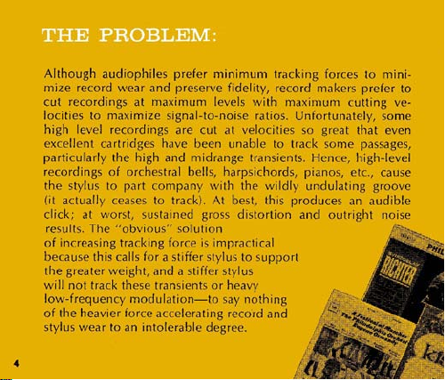
THE
Although audiophiles prefer minimum tracking forces to minimize record
cut recordings at maximum levels with maximum cutting velocities to maximize signal-to-noise ratios. Unfortunately, some
high level recordings are cut at velocities so great that even
excellent cartridges have been unable to track some passages,
particularly the high and midrange transients. Hence, high-level
recordings of orchestral bells, harpsichords, pianos, etc., cause
the stylus to part company with the
(it actually ceases to track). At best, this produces an audible
click; at worst,
of increasing tracking force is impractical
because this calls for a stiffer stylus to suppc
the greater weight, and a stiffer stylus
will not track these transients or heavy
low-frequency modulation-to say nothing
of the heavier force accelerating record and
stylus wear to an intolerable degree.
PROBLEM:
wear and preserve fidelity, record makers prefer to
result,. The "obvious"
wsta~ned gross distortion and outr~ght noise
wlldly undulating groove
soli~tion
Shure has collected scores of these demanding high level recordings and painstakingly and thoroughly analyzed them.
found that in some cases (after only a few
velocity high or midrange groove undulations were "shaved"
off or gouged out by the stylus
fidelity. Other records, which were off-handedly dismissed as
unplayable or poor pressings were found to be neither. They
were
s~rnply too high in recorded velocity and, therefore, un-
trackable by existing styli.
Most significantly, as a result of these analyses, Shure engineers
tablished the maximum recorded velocities of
various frequencies on quality records and
. . .
et about
would track the entire audible
playing) the high
thus eliminating the high
des~gning a cartridge that
ectrum of these maximum
velocities at tracking
forces of less than
1'12
It was
grams.
L
ENTER THE
COMPUTER
:
5
The solution to the problem of true trackability proved so
complex that Shure engineers designed an
puter that closely duplicated the mechanical variables and
characteristics of a phono cartridge. With this unique device, they were able to observe precisely what happened
when you varied the many factors which affect
ability: inertia of tip end of the stylus or the magnet end of
the stylus; the compliance between the record and the
needle tip, or the compliance of the stylus shank, or the
compliance of the bearing; the viscous damping of the
bearing; the tracking force; the recorded velocity of the
record, etc., etc. The number of permutations and
analog-com-
track-
com-

binatlons oi these elements, normally staggering, beca~~ic,
manageable. Time-consuming trial-and-error prototypes
were eliminated. Years of work were compressed into
months. After examining innumerable
design parameters evolved. Working with new materials
in new configurations, theory was made fact.
Thus, the first analog-computer-designed superior trackability cartridge was horn: the Shure SUPER-TRACK
TYPE
I1
It
groove at
and beyond the audible spectrum
highest
It also features an ingenious
guard.
It
the storied nightingale.
track~ng forces from
velocities
is
clean as the proverbial hound's tooth and musical as
maintains
contact between the stylus and record
3/4
encountered
"flip-actlon" built-in stylus
possibilities,
to
I1/z
grams, throughout
(20-25,000
In
quality recordings.
Hz),
new
V-15
at the

TRACKABILITY AS
A
NEW SPECIFICATION:
This chart depicts the new performance specification of
trackability. Unlike the oversimplified and generally
misunderstood design parameter specifications of compliance and mass, trackability is a measure of total performance. The chart shows frequency across the bottom, and modulation velocities
The outline of the yellow area represents the maximum
theoretical
ever, in actual practice many records are produced
which exceed these theoretical limits. The smoother the
curve of the individual cartridge being studied and the
greater its distance above the yellow area, the better the
trackability. The trackability of the Shure
shown by the top (solid black) lines. Representative
curves (actual) for other cartridges (prices indicated)
are shown for comparison purposes.
limits for cutting recorded velocities; how-
In
CM/SEC
up the side.
V-15
TYPE
II
is


SHURE
(-1
mm)
I-
4
(6
4
10
TOP VIEW
V-15
TYPE
I1 :DIMENSIONAL DRAWING
(9.5mrn) (9.5mm)
OPTIMUM PLAYING
POSITION
11

MOUNTING
The
V-15
Type
lI
(12.7
mm) mounting centers. Hardware is supplied with
each cartridge for mounting purposes. In some tone
arms and plug-in shells, the cartridge sits so deep that
the stylus cannot be conveniently replaced. For these
applications, spacers are provided to insure adequate
clearance for stylus removal.
For optimum vertical tracking angle, the cartridge
should be mounted so the top of the mounting block
is parallel to the record
SHURE-SME
To mount the V-15 Type
SME Precision Pickup Arm, Models 3009 and 3012, refer
to the paragraphs on Cartridge Installation and Balancing in the Instruction Manual supplied with the
pickup arms.
Dynetic Cartridge has standard
playing surface. (See Page
MOUNTING
lI
in the Shure-SME or the
'12"
11)
OPERATION
The recommended needle forces ior optimum results
are listed under "Speciiications." Forces greater than

indicated "Maximum" should not be used.
the
V-15
Type
II
The
arm especially designed for low tracking forces and
having low friction at all bearing surfaces such as the
Shure-SME arm. Although the
will track records at
when used in certain phono arms, to increase the
tracking force for optimum results.
The
V-15
as stereo records.
The
sign that prevents audible record-scratch or stylus damage when excessive force is applied to the stylus.
NOTE:
Type IIcartridges play monophonic
V-15
Type
For playing
cartridge should be installed in any
V-15
Type
11
3/4
gram, it may be necessary,
II
Styli incorporate a new retractile de-
78
R.P.M. records the Model
cartridge
LP
as well
N75-3
(.0027") Diamond Stylus is available.
CONNECTIONS
CAUTION:
ridge terminals. Make all solder connections to terminal
jacks provided. Soldering should not be done while
jacks are on cartridge terminals.
Do not make solder connections to car-

The Shure
arrangement for connections having a separate ground
terminal for each channel. (See illustration).
For Stereo reproduction terminal "R" and its ground
terminal "RC" represent the right channel (outside
groove wall). Terminal
"LC" represent the left channel (inside groove wall).
The metallic cartridge shield may be disconnected
from the right channel ground by the removal of the
ground tab.
$-Lead Stereo Connecfion: To use a 4-lead arrangement,
connect the "hot" lead of the right channel to terminal
"R" and the shield or ground lead of the right channel
to terminal
channel to terminal "L" and the shield or ground lead
of the left channel to "LC." To prevent "ground loops"
and hum, no common connection should be used at
the cartridge terminals.
V-15
Type
11
Cartridge utilizes a 4-terminal
"L"
and its ground terminal
"RC."
Connect the "hot" lead of the left

3-Lead Stereo Connection:
When a 3-lead stereo input
system is used, the common
lead should be connected
to both of the ground terminals at the cartridge. No
other common ground connection should exist.
LE
CH
TERMINAL
(BLUE
RIGHT CHANNEL
GROUND TERMINAL
GROUNDED TO CASE
BY
GROUND TAB
(GREEN RIN'C'

MONAURAL PLAYBACK
For reproduction ot monaural records, uslng a stereo system, the
arnplifler should be set to "Monaural" or "A & 6". When the
cartridge is used in a monaural system, connect the "hot" lead
"R"
and
"L"
to both
lead to both of the ground terminals marked
terminals and connect the ground or shield
"RG"
and "LC".
SPECIAL
The Stereo Dynetic stylus assembly used in these cartridges is
the most critical component.
ance standards of your cartridge, be certain that any replacement
stylus you buy bears the following
"This Stereo
Brothers, Inc." Avoid inferior imitations. They will seriously degrade the performance of your cartridge. All genuine "Dynetic"
styli are manufactured by Shure Brothers, Inc.
The stylus assembly, when installed in the cartridge, is practically
immune to damage during normal usage. However, care should
be taken to avoid bending or distorting the stylus assembly when
it is installed or removed.
NOTE
Dynetic stylus is
To
maintain the original perform-
certification
precision
on the package:
manufactured by Shure

STYLUS REPLACEMENT
Stylus replacement is very simple and fast. To replace-grasp
stylus guard between thumb and forefinger. Gently withdraw
stylus by
placement stylus between thumb and forefinger and insert into
stylus socket. Press stylus into socket until the molded housing of
the stylus touches the cartridge case. Care must be taken not to
allow the finger to
to the stylus tip or shank.
pull~ng forward out of cartridge. Grasp guard of re-
sl~p off the stylus guard, resulting In damage

GUARANTEE
Th~s Shure product is guaranteed in normal
use to be free from electrical and mechanical defects for a period of one year from
the date of purchase. Please retain proof of
purchase date. This guarantee includes all
parts and labor. This guarantee does not
include stylus wear.
Carefully repack the unit and return it to the
factory.
the unit to your dealer or authorized Shure
Service Center for repair. The unit will be
returned to you prepaid.
18
Shipping Instructions:
If outside the United States, return

Typical Trackab~l~ty (at 1 gram
400
Hz
(cprl-28 cm/iec; 5,000
1,000
Hz
Frequency Response. 20 tO 25,WO
Output Voltage: 3 5 mv per channel at 1,000
Channel Balance: Output
Channel Separation.
Track~ng
Recommended Load Impedance. Nominally 47,000
channel). Can
chanee
1npu;~apacitkce. 400-5b0 P~ca-Farads per channel, lncludlng tone
arm
wfring.
Inductance. 720 m~ll~henr~ei
Terminals: 4 terminal
V-15
TypeIIStylus: VNISE 51-Radlal Elliptical Stylus,
V-15 11-7 Stylus- VN7 Spher~cal Stylus, D~amond Tip.
Mounting: Standard
We~ght. Net welghtd.8 grams.
Manufactured under
3,055,988, 3,077,521, 3,077,522 and 3,463,889.
(cpi)-35 cm/rec: 10,000 Hz (cpil-22 cm/rec,
peak velocity
Force.
to 1'12 grams.
be
used up
In
freouencv
18 mlcronr 1.0007 ~nch) frontal radlur;
25 mlcrons 1001 lnchiwlde between record
contact
mlcronr 10007 ~nch) radius.
18
'12
unng a Shure/SME Tone
Hz
from
each channel withln 2 db.
Over
25 db at 1,000
Over
17 db from 500 to 10,000
to
70,000 ohmr wtth almost lnaudlble
resoonre.
Hz
(cpr)-30 cm/rec,
(cpri
Hz
(cpri at 5 cm/sec
Hz
(cpr)
Hz
D
C Resistance: 630 ohms.
Diamond
5 mlcroni (0002 ~nchl
po~nts
lnch (12,7 mm) mountlng center.
one
o. more of the following U.S. Patents
ride
contact radli;
(cpsl
ohmr
Arm)
[per
TIP.

QUALITY ASSURANCE CERTIFICATE
SHURE
V-15
TYPE
II
DYNETIC HIGH FIDELITY CARTRIDGES
The V-15 Type
has been manufactured under the Shure Master Quality Control Program. This program
embraces
to assure you that your V-15 Type
perfect operating
Shure quallty control not only covers incom-
ing parts and the finished product, but inter-
mediate sub-assemblies as well. For example:
every individual cartridge and every Stylus-
Magnet Assembly is tested and microscop-
ically examined. Each finished cartr~dge is
again tested electrically, mechanically and
acoustically against quality and tolerance spec-
ifications seldom achieved In the High Fldelity
I
Industry
stringent
SHURE BROTHERS, INC
222 Hartrey Avenue, Evanston, llllnois 60204
STEREO
I1
Stereo Dynetlc Cartridge
safeguards and standards
condition.
I1
Shure Performance,
Quality, Reliability
is in
4
?
3
5
$
Z
2
L;
r
;
5
2
3
6
2
0,
ID
m
v-
6'
Z
a
S
 Loading...