

Page 1

Performance Gear Series Wireless
Page 2

2
Patent numbers 6,597,301 and 6,296,565
Shure Performance Gear Wireless
Designed especially for performers who manage their own sound, Shure Performance Gear professional audio products deliver legendary Shure sound quality, stage-proven durability and hasslefree setup for worry-free performance.
Performance Gear Wireless systems are available in a variety of configurations - for handheld,
guitar, headset and presentation applications. Manual frequency selection and transmitter setup
provide specific choice and precise control to locate the clearest channel, every time.
System Components
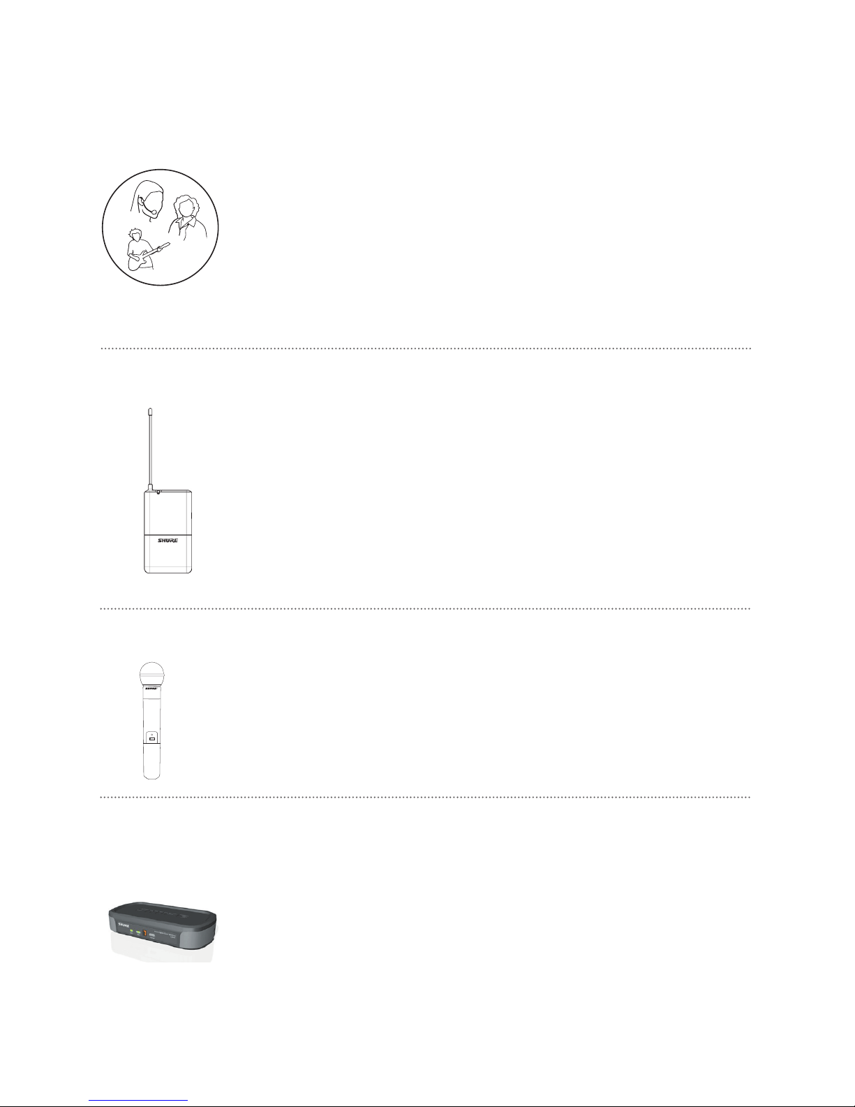
All systems include
Internal Antenna Diversity PG4 receiver
One 9 volt battery
Power supply
User guide
Vocalist systems include
Microphone Head
PG2 handheld transmitter
Microphone clip
Lavalier, Headworn, and Instrument systems include
PG1 body pack transmitter
Microphone (choice of PG185, PG30)
Guitar systems include
PG1 bodypack transmitter
4-pin mini connector (TA4F) to 1/4” connector cable
English
Page 3
3
PG4 Receiver Features
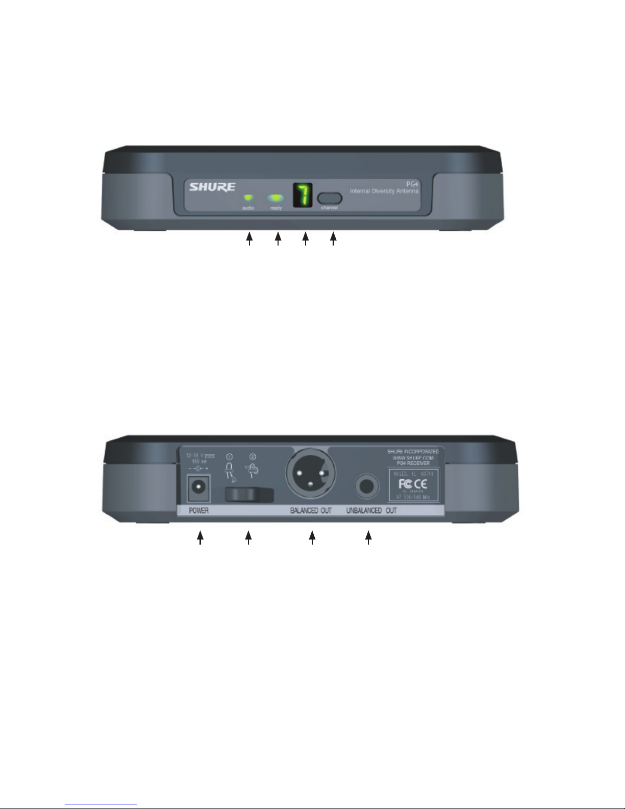
Figure 1. Front Panel
audio LED
Indicates strength of incoming audio signal: green for
normal, amber for strong, red for peak.
Channel Display
See “System Setup” on page 6.
ready LED
Green LED indicates system is ready for use.
channel button
Press and hold to change the frequency channel.
Figure 2. Back Panel
AC adapter jack XLR balanced microphone output jack
Adapter cord relief 1/4” unbalanced output jack
English
Page 4
4
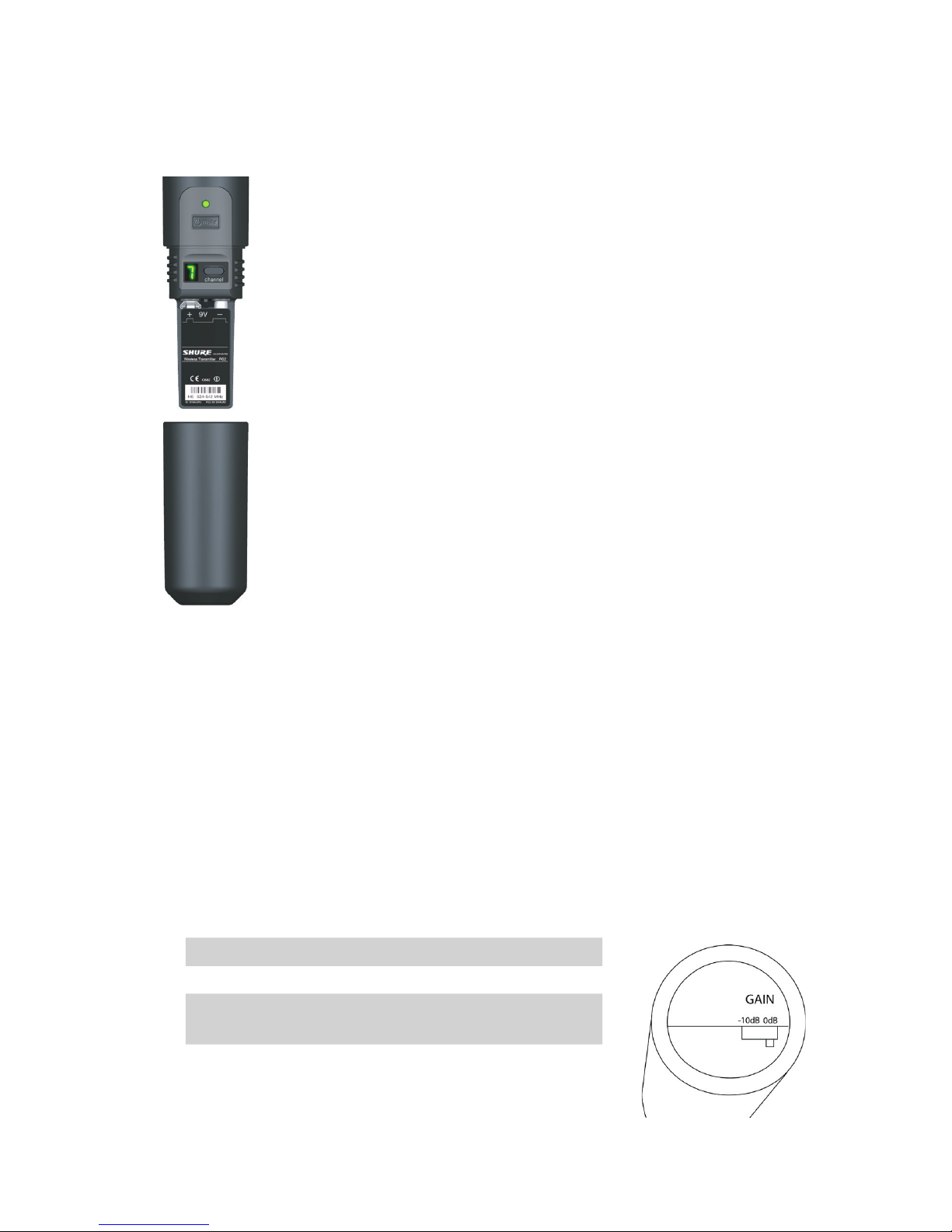
PG2 Handheld Transmitter
Power/Mute Button
Power/Mute LED (See LED status below)
Channel Display (Display turns off after 10 seconds to conserve battery)
Channel Button
Battery Cover — Twist counter-clockwise to remove.
Battery Compartment
LED Status Signifies
Green Ready
Amber Mute is on
Red Battery is low
Flashing Red
on startup
Battery dead (must be replaced for transmitter to operate).
Flashing Green
and Red
Controls are locked
Flashing Amber
and Red
Mute is on and battery is low
Changing Battery
• Expected life for a 9 volt alkaline battery is approximately 8 hours.
• When the Power/Mute LED glows red, the battery should be replaced immediately.
Adjusting Gain
• Access the Gain Adjustment Switch by unscrewing the microphone head.
Use the tip of a pen or a small screwdriver to move the switch. (See fig. 4)
• The switch can be positioned in two gain settings on the PG2:
Gain Setting Suggested Uses
0dB For quiet to normal vocal performance.
–10dB Use only if audio is distorted due to high vocal
levels.
Figure 3.
Figure 4.
English
Page 5
5
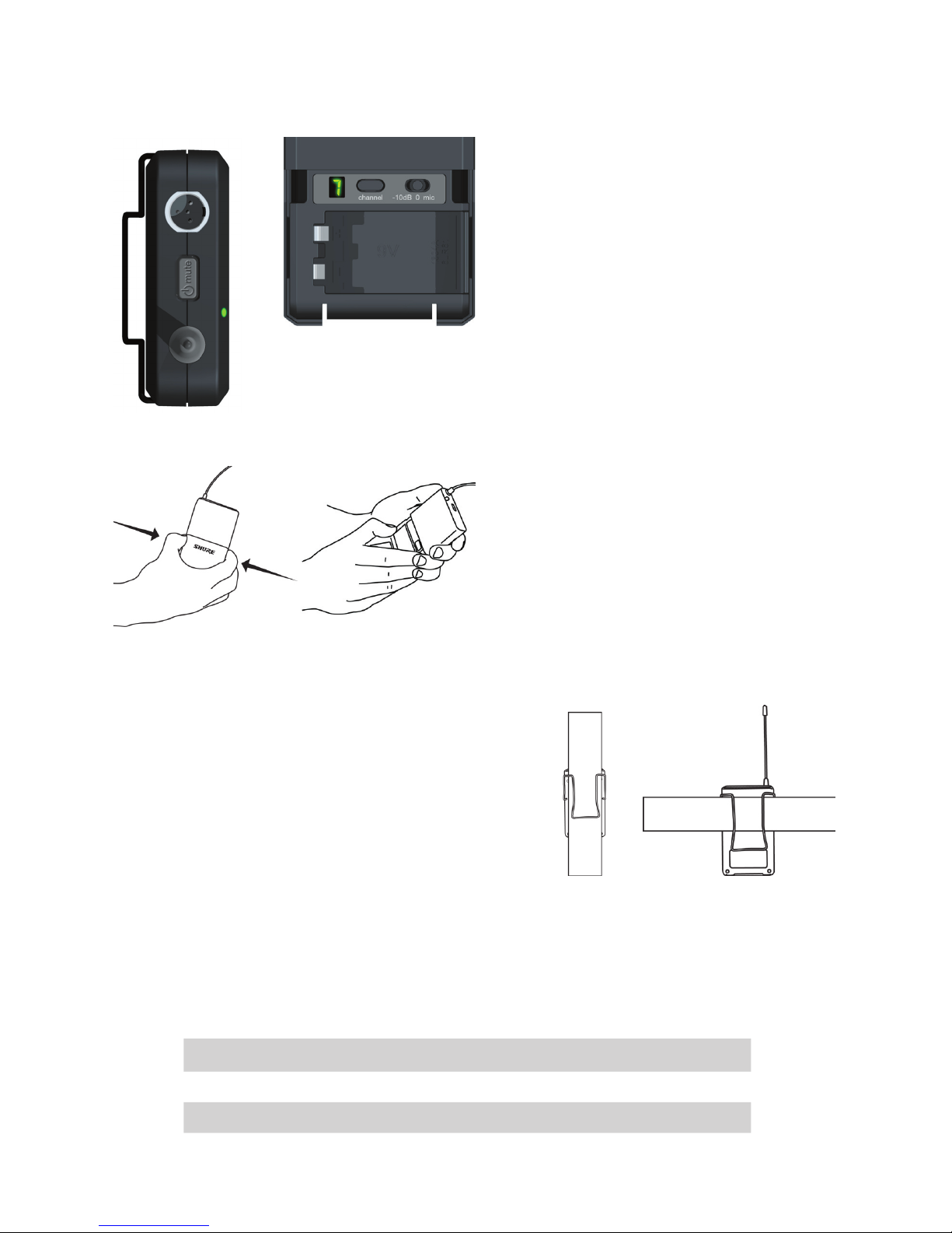
PG1 Bodypack Transmitter
4-Pin Microphone Input Jack
Power/Mute Button. Press and hold to turn on/off.
Press and release to mute/unmute.
Power/Mute LED (see LED Status below)
Antenna
Channel Display
Channel Button
Gain Switch
9V Battery compartment
Battery Cover. Pinch sides to fold open.
LED Status Signifies...
Green Ready
Amber Mute is on
Red Battery is low
Flashing red on
startup
Battery dead (must be replaced for
transmitter to operate).
Flashing Green
and Red
Flashing Green and Red
Flashing Amber
and Red
Mute is on and battery is low
Wearing the Bodypack Transmitter
• Clip the transmitter to belt or guitar strap as
shown. If using a belt, slide the transmitter until
the belt is pressed against the base of the clip.
Changing Battery
• Expected life for a 9 volt alkaline battery is
approximately 8 hours.
• When the Power/Mute LED glows red, the
battery should be replaced immediately.
Adjusting Gain
• Three gain settings are available on the PG1:
Gain Settings Suggested Use
mic Microphone
0 Guitar
-10 Use only if audio is distorted due to high input level
Figure 6.
Figure 5.
Figure 7.
Battery Cover, pinch sides to fold open
English
Page 6

6
Figure 8.
Figure 9.
System Setup
English
In any wireless setup, each transmitter and receiver pair must be tuned to the same frequency, or
channel. Follow these steps to set the transmitter and receiver to the same channel:
1. Plug in the receiver to turn power on. Turn transmitter power off.
2. Press and hold the channel button on the receiver for about one second to enter select
mode. Release the button as soon as the display begins flashing.
3. Press the channel button while the number is flashing to change to the next channel *.
4. To activate a newly selected channel, simply wait until the number stops flashing.
5. Turn on the corresponding transmitter.
6. Press and hold the channel button on the transmitter to enter select mode. Release the
button as soon as the display begins flashing.
7. Press the channel button while the number is flashing to change to the next channel.
Scroll through the channels until the transmitter setting matches the channel on the
receiver.
8. The transmitter channel is set when the number stops flashing. The green “ready” LED
on the receiver will indicate the system is ready for use.
Single Receiver Setup
*Note: Some of the frequencies available on the PG4 receiver may be occupied by sources of
interference such as broadcast television or other wireless devices. Use the Busy Indicator on the receiver channel display to avoid selecting an occupied channel while in select
mode.
Busy Indicator
When selecting channels, if the display flashes between a number and a blank screen, the channel
is clear. If the display flashes between a number and a dash as shown in Figure 9, the channel is
busy. This means that the channel is occupied by another device or source of interference. In this
case, it is recommended to select another channel.
Page 7
7
To set up multiple systems, repeat the previous steps for each transmitter and receiver pair. Once
transmitters have been set, leave them on. Be sure to set each transmitter and receiver pair to a
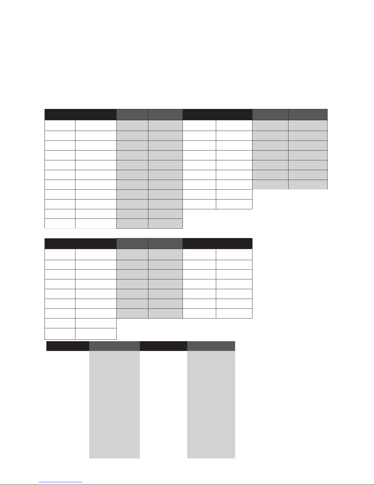
different frequency. For information about frequencies and compatibility, refer to the guide below.
Multiple System Setup
In each group, channels 1,3,5,7 and 9 are a compatible set and channels 2,4,6,8 and 0 are a
compatible set. When operating multiple systems, select only odd or even numbered channels for
best results.
TLPW Frequency and Channel Guide
English
M10 674-686 R10 800-812 P11 702-714 Q11 740-752
CH Freq CH Freq CH Freq CH Freq
1 674.775 1 802.100 1 702.150 1 740.150
2 676.700 2 803.675 2 703.600 2 741.600
3 677.900 3 805.750 3 705.500 3 743.500
4 682.025 4 809.100 4 707.100 4 746.400
5 685.500 5 810.550 5 708.400 5 748.100
6 674.025 6 802.325 6 710.100 6 751.850
7 680.975 7 803.550 7 712.650
8 682.775 8 805.100 8 713.850
9 684.000 9 808.600
0 685.900 0 810.025
R11 770-782 R12 794-806 JB 806-810
CH Freq CH Freq CH Freq
1 770.150 1 794.150 1 806.125
2 771.600 2 797.500 2 806.375
3 773.500 3 799.100 3 807.125
4 775.100 4 800.400 4 807.750
5 776.400 5 802.100 5 809.000
6 778.100 6 805.850 6 809.500
7 780.650
8 781.850
H7 536 - 548 K7 590 - 602 M7 662-674 T10 854 - 865
CH Freq CH Freq CH Freq CH Freq
1 536.050 1 590.050 1 662.050 1 854.900
2 542.050 2 596.050 2 668.050 2 856.575
3 537.400 3 591.400 3 663.400 3 857.950
4 543.400 4 597.400 4 669.400 4 861.750
5 539.175 5 593.175 5 665.175 5 863.900
6 545.175 6 599.175 6 671.175 6 855.275
7 540.375 7 594.375 7 666.375 7 857.925
8 546.375 8 600.375 8 672.375 8 861.550
9 541.975 9 595.975 9 667.975 9 863.200
0 547.975 0 601.975 0 673.975 0 864.500
Page 8
8
Troubleshooting
Issue LED Status Solution
No sound or faint
sound
Transmitter Power/Mute
LED on, receiver LEDs on
• Perform transmitter setup (see page 6).
• Verify all sound system connections.
• Adjust transmitter gain.
Receiver Channel Display • Make sure AC adapter is securely plugged into electrical outlet and into
POWER connector on rear panel of receiver .
• Make sure AC electrical outlet works and is supplying proper voltage.
Transmitter LED glowing or
flashing red
• Replace transmitter battery.
Transmitter LED off • Turn transmitter on.
• Make sure the +/– indicators on battery match transmitter terminals.
• Insert fresh battery.
Distortion or unwanted noise bursts
• Remove nearby sources of RF interference (CD players, computers, cell
phones, digital effects, in-ear monitor systems, etc.)
• Change receiver and transmitter to a different frequency.
• Reduce transmitter gain.
• Replace transmitter battery.
• If using multiple systems, change the frequency of one of the active systems.
Sound level different from cabled guitar or microphone, or when using different guitars
• Adjust transmitter gain as necessary.
Cannot turn
transmitter on
Transmitter LED flashing
red
• Replace transmitter battery.
Locking and Unlocking Controls
Locking the system controls prevents accidental muting or channel adjustment during performance.
Transmitter
To lock the controls: turn the transmitter off, hold the channel button down and turn the transmitter
power on. The Power/Mute LED will alternate between red and green.
To unlock the controls: with the transmitter on, hold the channel button down, and turn the
transmitter off.
Page 9
9
Specifications
System
Working Range 75m (250 ft.) Note: actual range depends on RF signal absorption, reflection,
and interference.
Audio Frequency Response Minimum: 45 Hz.
Maximum: 15 kHz (overall system frequency depends on microphone element).
Total Harmonic Distortion
0.5%, typical
Ref. +/– 33 kHz deviation, 1 kHz tone
Dynamic Range >100 dB A-weighted
Operating Temperature
Range
–18°C (0°F) to +57°C (+135°F) Note: battery characteristics may limit this
range
Transmitter Audio Polarity
Positive pressure on microphone diaphragm (or positive voltage to tip of
WA302 phone plug) produces positive voltage on pin 2 (with respect to pin 3 of
low impedance output) and the tip of the high impedance 1/4-inch output.
PG1 Bodypack
Transmitter
Audio Input Level –10 dBV maximum at “mic” gain position
+10 dBV maximum at 0dB gain position
+20 dBV maximum at –10dB gain position
Gain Adjustment Range
30 dB
Input Impedance 1MΩ
RF Transmitter Output
10 mW typical
Dimensions 110 mm H x 64 mm W x 21 mm D (4.3 x 2.5 x 0.8 in.)
Weight
75 grams (2.6 oz.) without battery
Housing Molded poly carbonate case
Power Requirements One 9V alkaline battery
Battery Life >8 hours (alkaline)
PG2 Handheld
Transmitter
Audio Input Level +2 dBV maximum at –10dB position
–8 dBV maximum at 0dB position
Gain Adjustment Range
10dB
RF Transmitter Output
10 mW typical
Weight
218 grams (7.7 oz.) without battery
Housing Molded PC/ABS handle and battery cup
Power Requirements One 9V size alkaline or rechargeable battery
Battery Life >8 hours (alkaline)
PG4 Receiver
Dimensions 188 mm L x 103 mm W x 40 mm D (7.4 in. x 4.0 in. x 1.5 in.)
Weight
241 grams (8.5 oz)
Output Impedance XLR connector: 200 Ω 1/4 inch connector: 1kΩ
Housing ABS
Audio Output Level Ref.
+/– 33 kHz deviation with 1
kHz tone
XLR connector (into 600 Ω load): –19 dBV
1/4 inch connector (into 3000 Ω load): –5 dBV
Sensitivity –105 dBm for 12 dB SINAD, typical
Image Rejection >50 dB, typical
Power Requirements 12–18 Vdc at 150 mA, supplied by external power supply
English
Page 10

10
Replacement Parts
All Systems Microphone Stand Adapter (PGX2) WA371
System-Specific AC Adapter (120 VAC, 60 Hz)
PS20
AC Adapter (230 VAC, 50/60 Hz, Europlug)
PS20E
AC Adapter (230 VAC, 50/60 Hz, UK)
PS20UK
AC Adapter (100 VAC, 50/60 Hz)
PS20J
AC Adapter (220 VAC, 50 Hz, China)
PS20CHN
PG58 Head with Grille RPW108
Belt Clip 44A8035
Optional Universal Rack Tray URT
4-pin mini connector (TA4F) to 1/4” connector cable WA302
English
Page 11

11
Regulatory Information for North America, Europe, and Australia
PG1 & PG2 Transmitters: Certified to FCC Part 74 (FCC ID: “DD4PG1” and “DD4PG2”). Certified
by IC in Canada under RSS-123 and RSS-102 (“IC: 616A-PG1” and “IC: 616A-PG2”). Meets the
essential requirements of the European R&TTE Directive 99/5/EC (ETSI EN 300-422 Parts 1 & 2,
EN 301 489 Parts 1 & 9) and are eligible to carry the CE marking.
N108
English
Regulatory Information
PG4 Receiver: Authorized under Declaration of Conformity (DoC) provision of FCC Part 15. Certified under Industry Canada to RSS-123 (“IC: 616A-PG4”). This class B digital apparatus complies
with Canadian ICES-003. Meets the essential requirements of the European R&TTE Directive
99/5/ EC (EN 301 489 Parts 1 & 9, EN 300 422 Parts 1 & 2) and is eligible to carry the CE marking.
Conforms to Australian EMC requirements and is eligible for C-Tick marking.
NOTE: This equipment has been tested and found to comply with the limits for a Class B digital
device, pursuant to Part 15 of the FCC Rules. These limits are designed to provide reasonable
protection against harmful interference in a residential installation. This equipment generates,
uses and can radiate radio frequency energy and, if not installed and used in accordance with
the instructions, may cause harmful interference to radio communications. However, there is no
guarantee that interference will not occur in a particular installation. If this equipment does cause
harmful interference to radio or television reception, which can be determined by turning the equipment off and on, the user is encouraged to try to correct the interference by one or more of the
following measures:
-- Reorient or relocate the receiving antenna.
-- Increase the separation between the equipment and receiver.
-- Connect the equipment into an outlet on a circuit different from that to which the receiver is
connected.
-- Consult the dealer or an experienced radio/TV technician for help.
PS 20 Series Power Supplies: Conform to Safety Standard IEC 60065. PS20E and PS20UK are
eligible to bear CE marking.
A ministerial license may be required to operate this equipment in certain areas.
Consult your national authority for possible requirements.
This radio equipment is intended for use in musical professional entertainment and similar applications.
Caution: changes or modifications not expressly approved by Shure Incorporated for compliance
could void the user’s authority to operate the equipment.
Operation of this device is subject to the following two conditions: (1) this device may not cause interference, and (2) this device must accept any interference, including interference that may cause
undesired operation of the device.
0978
Z540
0978
Page 12

12
SHURE Incorporated http://www.shure.com
United States, Canada, Latin America, Caribbean:
5800 W. Touhy Avenue, Niles, IL 60714-4608, U.S.A.
Phone: 847-600-2000 U.S. Fax: 847-600-1212
Int’l Fax: 847-600-6446
Europe, Middle East, Africa:
Shure Europe GmbH, Phone: 49-7131-72140 Fax: 49-7131-721414
Asia, Pacifi c:
Shure Asia Limited, Phone: 852-2893-4290 Fax: 852-2893-4055
 Loading...